Coast to Coast Coast Awning Wall Kits User manual
Coast Awning Wall KitsCoast Awning Wall Kits
Increase your outdoor living space with Coast to Coast’s stylish and easy to Increase your outdoor living space with Coast to Coast’s stylish and easy to
install install Awning Wall Kits for CaravansAwning Wall Kits for Caravans
Before you begin, please note the following:Before you begin, please note the following:
Coast Awning Wall Kits are available to suit rollout awnings from 12Coast Awning Wall Kits are available to suit rollout awnings from 12—
—18 (3.66mt18 (3.66mt—
—5.47mt) in 1 5.47mt) in 1
increments.increments.
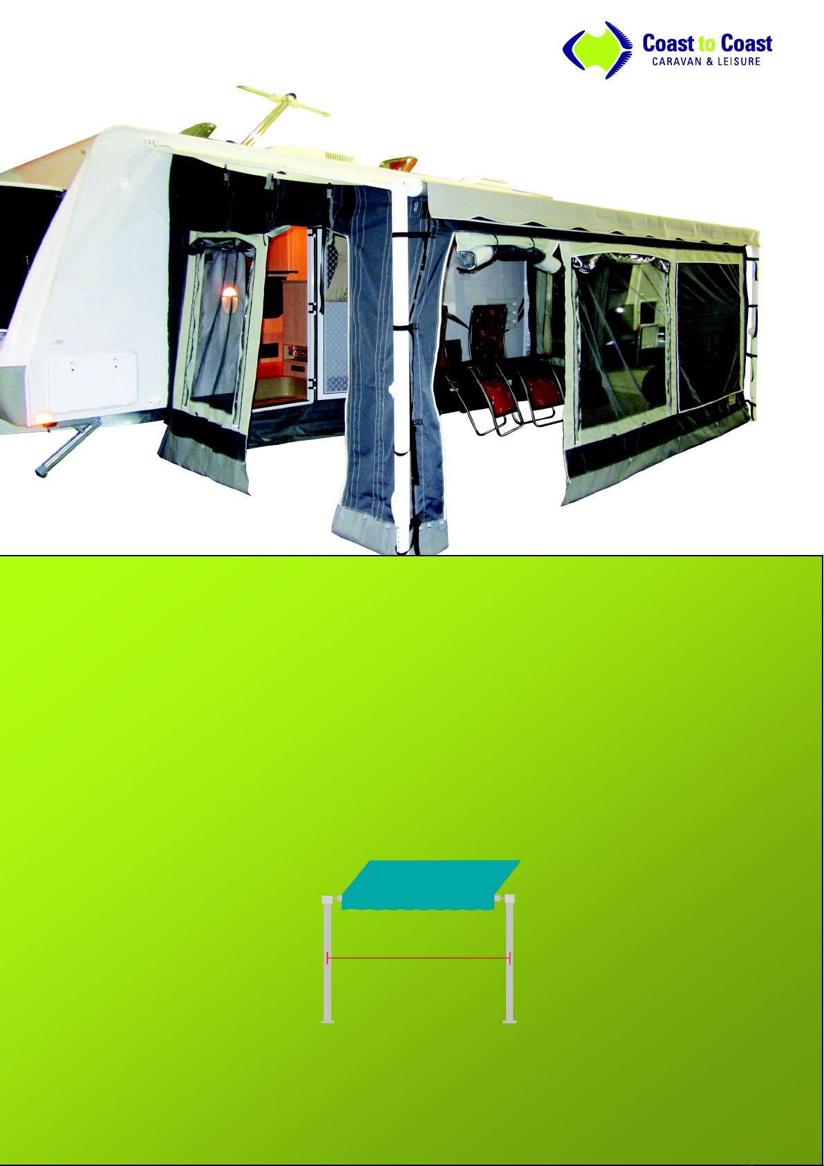
To ensure you purchase the correct size Awning Wall Kit, it is recommended that you measure the To ensure you purchase the correct size Awning Wall Kit, it is recommended that you measure the
width of your rollout awning from the centre of the le arm to the centre of the right arm. *Please width of your rollout awning from the centre of the le arm to the centre of the right arm. *Please
refer to the diagram below:refer to the diagram below:
Once you are ready to begin installaon, park your Caravan in a desired posion, make sure the hand-Once you are ready to begin installaon, park your Caravan in a desired posion, make sure the hand-
brake is on and your van is level frontbrake is on and your van is level front-
-toto-
-back and sideback and side-
-toto-
-side.side.

Sizes Available:
150-03000 AWNING WALL KIT TO SUIT 12'ROLLOUT AWNING 150-03010 AWNING WALL KIT TO SUIT 13' ROLLOUT AWNING
150-03020 AWNING WALL KIT TO SUIT 14' ROLLOUT AWNING 150-03030 AWNING WALL KIT TO SUIT 15' ROLLOUT AWNING
150-03040 AWNING WALL KIT TO SUIT 16' ROLLOUT AWNING 150-03050 AWNING WALL KIT TO SUIT 17' ROLLOUT AWNING
150-03060 AWNING WALL KIT TO SUIT 18' ROLLOUT AWNING
Step 1
Rollout your awning to the pao posion as shown
Take the pull-down strap out of the awning roller tube
Peg/ secure the awning legs to the ground
Your awning roller tube should be set at 6 ‘o clock, i.e. the
third grooved track is facing straight down
Step 2
It is recommended to set the front roller tube height to
6’1” - 6’3” (1.86mt - 1.91mt) on the le and right side of
the awning (measuring from the boom of the roller
tube to the ground)
Unpack your Awning Wall Kit and locate the front wall
panel—this has zips at both ends
Step 3
Unzip the transion piece from the front wall (this makes
threading it through the rope track on your roller tube
much easier)
With the zipper facing you, thread the transion piece
through the rope track
Ensure the transion piece is now posioned in the middle
of the roller tube. You can check this by measuring the
distance from the end of the transion piece to the end of
the roller tube on the right side. Once you have this meas-
urement, compare it to the le side.
Step 4
It’s now me to aach the front wall to the transion
piece
Make sure the yscreen is facing you and clip the front
wall to the transion piece using the caribee clips
Once this is done, you can zipper the two pieces togeth-
er, creang a solid barrier against the elements
Pao Posion
Front Wall
Step 5
Tie the black webbing straps on the ends of the front wall
to the awning arm by threading through the buckle (there
are 4 on each side of the front wall)
Once you have ed up both sides, make sure the front
wall is sll centralised on the roller tube of the awning
Locate the telescopic raer pole (this is the one with spig-
ots on both ends)
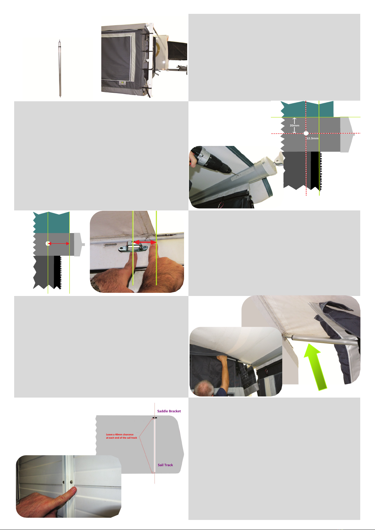
Step 6
Line the edge of the telescopic raer pole to the edge of
the front wall (not awning fabric)—the spot which the spig-
ot points is where you should drill a pilot hole into the awn-
ing roller tube
It is recommended to make the pilot hole 20mm under the
awning canopy and 12.5mm in from the edge of the front
wall
*Note: When drilling the nal hole, be careful not to over penetrate the roller tube.
If you go too far, you risk damaging the internal spring mechanism. It is recom-
mended to use a 11/32” (8.73mm) drill bit to drill your nal holes.
Step 7
Remove any burrs from the drill site—you can use a round
metal le to smoothen the edges
Locate the saddle brackets—these need to be installed
onto the side of your Caravan approx. 20mm under your
awning vinyl
*Note: Ensure that the centre hole of the saddle bracket measures the same dis-
tance from the edge of the awning canopy as the drilled hole on the roller tube
Step 8
The end of the telescopic raer pole which has a thicker
circumference needs to have its spigot trimmed down to
15mm. Once this is done, insert the telescopic raer pole
into the bracket on the pop top and the hole in the roller
tube
At this point you will need to make a decision on whether
you want to connue the installaon process using sail
track (which will have to be screwed onto the outside wall
of your RV) or if you want to use the tent poles provided
Sail Track—Step 1:
Coast recommends the use of double sided sail track but
you may nd that near window/ door frames space is lim-
ited—in this instance, single sided sail track is ne
The sail track should be installed directly below (and in-
line) with the saddle bracket
When installing the sail track remember to use stainless
steel screws and ensure they are applied to your RV’s clad-
ding joints
*Note: Remember to seal the screw sites with a silicone sealant. Also make sure
the screws are not too long, otherwise they will damage the inside wall of your
RV!
Telescopic
Raer
Pole
Telescopic Raer
Pole
=
Sail Track—Step 2:
Use a foam tape like 3M on the underside of the sail track
prior to screwing, this creates a sealant and also lls the
recesses on your RV outer wall. (Alternavely, use an ap-
proved sealant as per the manufacturers specicaons)
File any sharp edges away and are the ends of the sail
track
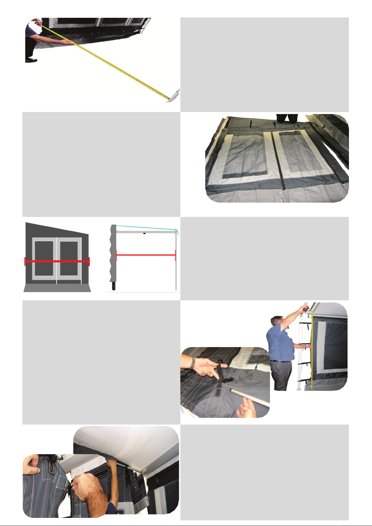
Measure the distance from the sail track to the front wall
Sail Track—Step 3:
Locate a side wall panel (these are the ones with two
windows) and unroll it at on the ground
Measure the width of the side wall panel as it will
need to be the same as the width from the sail track
to the front wall panel
Each side wall panel can be adjusted to t varying
projecon widths by means of adjustable inll panels.
For your convenience, each kit comes with two S, M
and L inll panels
Sail Track—Step 4:
Use the appropriate inll panel and aach to the side wall
panel by means of the extra wide (50mm) Velcro strip.
You may nd that you don’t need an inll panel at all but
this depends on your awning projecon
Measure the width of the side wall panel you’ve just cre-
ated and make sure it is the same as the distance from
the sail track to the front wall panel
Sail Track—Step 5:
You now need to thread the telescopic raer pole
through the loops on the inside of the side wall pan-
el. To do this you need to measure the oor—vinyl
height at the front of the awning and the back of the
awning
Line the telescopic raer pole up with the rst and
last loops that you need, this will indicate which of
the remaining loops the pole should go through
There are x5 elascized pole clips for each side wall.
Tie these (as markers) to the loops that the telescopic
raer pole should go through
Sail Track—Step 6:
Thread the telescopic raer pole through the loops with
the elascised clips on it
Pick up the side wall panel by the pole (and remember
that the yscreen should face you) and insert each spigot
end into its corresponding hole on the roller tube and the
bracket on the pop top
Once the side wall is securely in posion, zipper it to the
front wall panel
=

Sail Track—Step 7:
Aach the side wall to your RV by threading the white
strip into your sail track, the easiest way to do this is by
detaching this from the side wall and then rmly press-
ing the Velcro back together once threaded
For the nishing touches on the side wall, simply roll up
the excess material and clip it onto the telescopic raer
pole by using the elascised clips
Sail Track—Step 8:
You can also cut strips into the PVC near the roller tube
to achieve a ush t
You need to aach the awning vinyl to the side wall,
this is done by clipping the suspender buckles to the
canopy. We’ve included a vinyl strip to protect your
awning vinyl
You can also dy the extra strapping on the suspender
buckles, by using the black bands supplied
Pole—Step 1:
Follow the steps as previously outlined (on how to
aach the front and the side wall panels)
With the side wall in posion, locate a telescopic pole
(one end has a rubber foot and the other has a U-
shaped clip), this needs to be inserted into the pole cav-
ity on the side wall panel
Open the receiving pocket and slot the telescopic pole
inside, keeping in mind that the U-shaped end should be
rmly clipped onto the telescopic raer pole (that the
side wall is hanging o of)
Close the pole cavity
Telescopic Pole
Other Coast to Coast Automobile Accessories manuals


Popular Automobile Accessories manuals by other brands


ULTIMATE SPEED
ULTIMATE SPEED 279746 Assembly and Safety Advice

SSV Works
SSV Works DF-F65 manual

ULTIMATE SPEED
ULTIMATE SPEED CARBON Assembly and Safety Advice

Witter
Witter F174 Fitting instructions

WeatherTech
WeatherTech No-Drill installation instructions

TAUBENREUTHER
TAUBENREUTHER 1-336050 Installation instruction