Coats 9500 User manual

1601 J. P. Hennessy Drive, LaVergne,TN USA 37086-3565 615/641-7533 800/688-6359 Manual Part No.: 8184344 02
HENNESSY INDUSTRIES INC. Manufacturer of AMMCO®, COATS®and BADA®Automotive Service Equipment andTools. Revision: 01/04
9500
Electro-HydraulicTire Changer
For Medium and Large SizeTires
®
Installation Instructions
Operating Instructions
Safety Instructions
Maintenance Instructions
READ these instructions before placing unit in
service KEEP these and other materials delivered
with the unit in a binder near the machine for
ease of reference by supervisors and operators.
IMPORCOM EQUIPOS AUTOMOTRICES
Blvd. Leyva Solano #830 A Pte.
Culiacan Sinaloa CP 80000
(667) 276 8141
(667) 716 0102
ID 92*1038450*4

ii • COATS 9500Tire Changer
Table of Contents
Safety Instructions . . . . . . . . . . . . . . . . . . . .ii-iv
Definitions of Hazard Levels . . . . . . . . . . . . . . .ii
Operator Protective Equipment . . . . . . . . . . . .iii
Safety Devices . . . . . . . . . . . . . . . . . . . . . . . . . .iii
Important Safety Instructions . . . . . . . . . . . . . .iii
Safety Precautions . . . . . . . . . . . . . . . . . . . . . . .iii
Bead Loosening Safety . . . . . . . . . . . . . . . . . . .iv
Demounting & Mounting Safety . . . . . . . . . . .iv
Inflation Safety . . . . . . . . . . . . . . . . . . . . . . . . . .iv
1.0 Introduction . . . . . . . . . . . . . . . . . . . . . . .1-4
1.1 Use Limitations . . . . . . . . . . . . . . . . . . . . . . .1
1.2 Notice . . . . . . . . . . . . . . . . . . . . . . . . . . . . . . .1
1.3 General Safety Instructions . . . . . . . . . . . . .1
1.4 Nomenclature . . . . . . . . . . . . . . . . . . . . . . . .1
1.5 Specifications . . . . . . . . . . . . . . . . . . . . . . . .2
1.6 Dimensions OfThe Machine . . . . . . . . . . . .2
1.7 Standard Accessories . . . . . . . . . . . . . . . . . .2
1.8 Optional Accessories . . . . . . . . . . . . . . . . . .3
2.0 Carriage Instructions . . . . . . . . . . . . . . . . . .4
2.1 Uncrating Instructions . . . . . . . . . . . . . . . . .4
2.2 Installation Area . . . . . . . . . . . . . . . . . . . . . .4
3.0 Installation Instructions . . . . . . . . . . . . . . .5
3.1 Electric Installation . . . . . . . . . . . . . . . . . . . .5
3.2 Motor Rotation Check . . . . . . . . . . . . . . . . . .5
Operating Instructions . . . . . . . . . . . . . . . . .6-17
4.0 Controls . . . . . . . . . . . . . . . . . . . . . . . . . . .6-7
5.0 Mounting And Demounting - General
Precautions . . . . . . . . . . . . . . . . . . . . . . . . . .7
5.1 Locking Rims . . . . . . . . . . . . . . . . . . . . . . . . .7
5.2 DemountingTubelessTruckTires
(UpTo 13”Wide) . . . . . . . . . . . . . . . . . . . .8-9
5.3 MountingTubelessTruckTires
(UpTo 13”Wide) . . . . . . . . . . . . . . . . . . .10-11
5.4 Demounting Duplex And Supersingle
TubelessTruckTires (Over 13”Wide) . . . .12
5.5 Mounting Duplex And Supersingle
TubelessTruckTires (Over 13”Wide) . .12-13
5.6 DemountingTires From Multi-Piece
Rim/Wheel Assemblies . . . . . . . . . . . . . . . .14
5.7 MountingTires Onto Multi-Piece
Rim/Wheel Assemblies . . . . . . . . . . . . . . . .15
5.8 DemountingTractor And O.T.R.
WheelsWith One-Piece Rims . . . . . . . .15-17
5.9 MountingTractor And O.T.R.
Wheels On One-Piece Rims . . . . . . . . . . . .17
6.0 Maintenance . . . . . . . . . . . . . . . . . . . . . . .18
7.0 MovingThe Machine . . . . . . . . . . . . . . . . .18
8.0 StoringThe Machine . . . . . . . . . . . . . . . . .18
10.0Trouble Shooting . . . . . . . . . . . . . . . . . . .19
Safety Instructions
Failure to follow danger, warning, and caution instruc-
tions may lead to serious personal injury or death to
operator or bystander or damage to property. Do not
operate this machine until you read and understand
all the dangers, warnings and cautions in this man-
ual. For additional copies of either, or further informa-
tion, contact:
Hennessy Industries, Inc.
1601 J.P. Hennessy Drive
LaVergne,TN 37086-3565
(615) 641-7533 or (800) 688-6359
www.ammcoats.com
Definitions of Hazard Levels
Identify the hazard levels used in this manual with the
following definitions and signal words:
DANGER
Watch for this symbol:
It Means: Immediate hazards, which will result in
severe personal injury or death.
WARNING
Watch for this symbol:
It Means: Hazards or unsafe practices, which could
result in severe personal injury or death.
CAUTION
Watch for this symbol:
It Means: Hazards or unsafe practices, which may result
in minor personal injury or product or property damage.
SAFETYALERT
Watch for this symbol! It means BE ALERT!
Your safety, or the safety of others, is
involved!
CAUTION
WARNING
DANGER
WARNING
WARNING
Read entire manual
before assembling,
installing, operating,
or servicing this
equipment.

COATS 9500Tire Changer • iii
Operator Protective Equipment
Personal protective equipment helps make tire servic-
ing safer. However, equipment alone does not take the
place of safe operating practices. Always wear durable
work clothing during tire service activity. Loose fitting
clothing should be avoided. Tight fitting leather gloves
are recommended to protect operator’s hands when
handling worn tires and wheels. Sturdy leather work
shoes with steel toes and oil resistant soles should be
used by tire service personnel to help prevent injury in
typical shop activities. Eye protection is essential during
tire service activity. Safety glasses with side shields,
goggles, or face shields are acceptable. Back belts pro-
vide support during lifting activities and are also helpful
in providing operator protection. Consideration should
also be given to the use of hearing protection if tire
service activity is performed in an enclosed area, or if
noise levels are high.
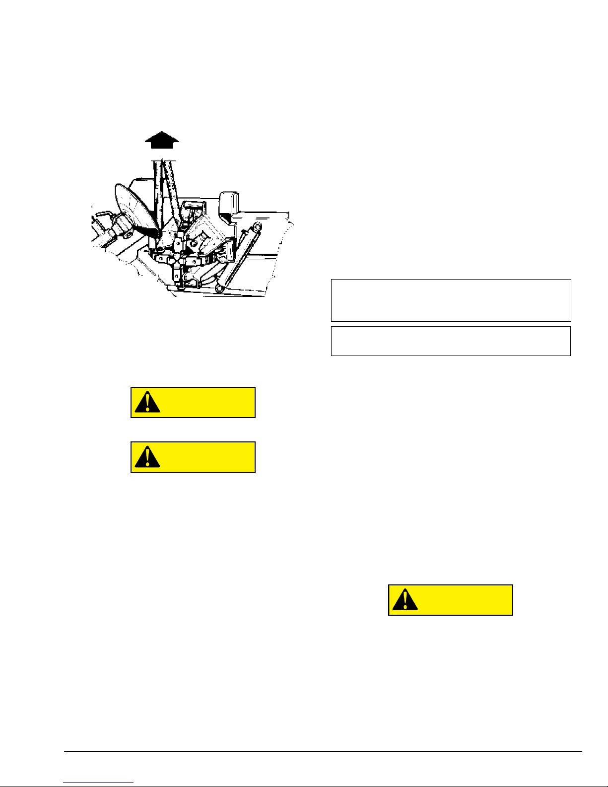
Safety Devices
This machine has several protectors to prevent com-
pression or crushing hazards to body areas. Keep these
devices properly maintained and do not disable or in
any way shortcut the safety controls and opertations.
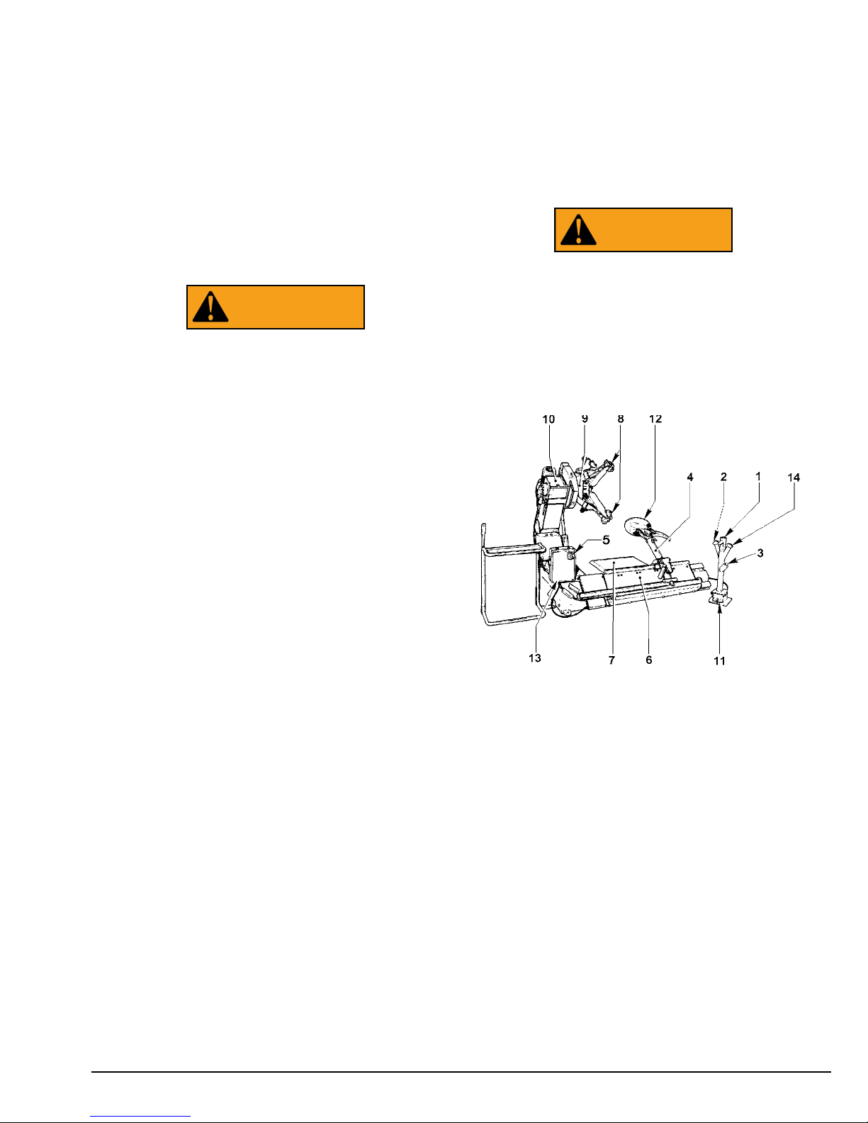
There is a micro-switch protection under the chuck
arm to prevent compression.
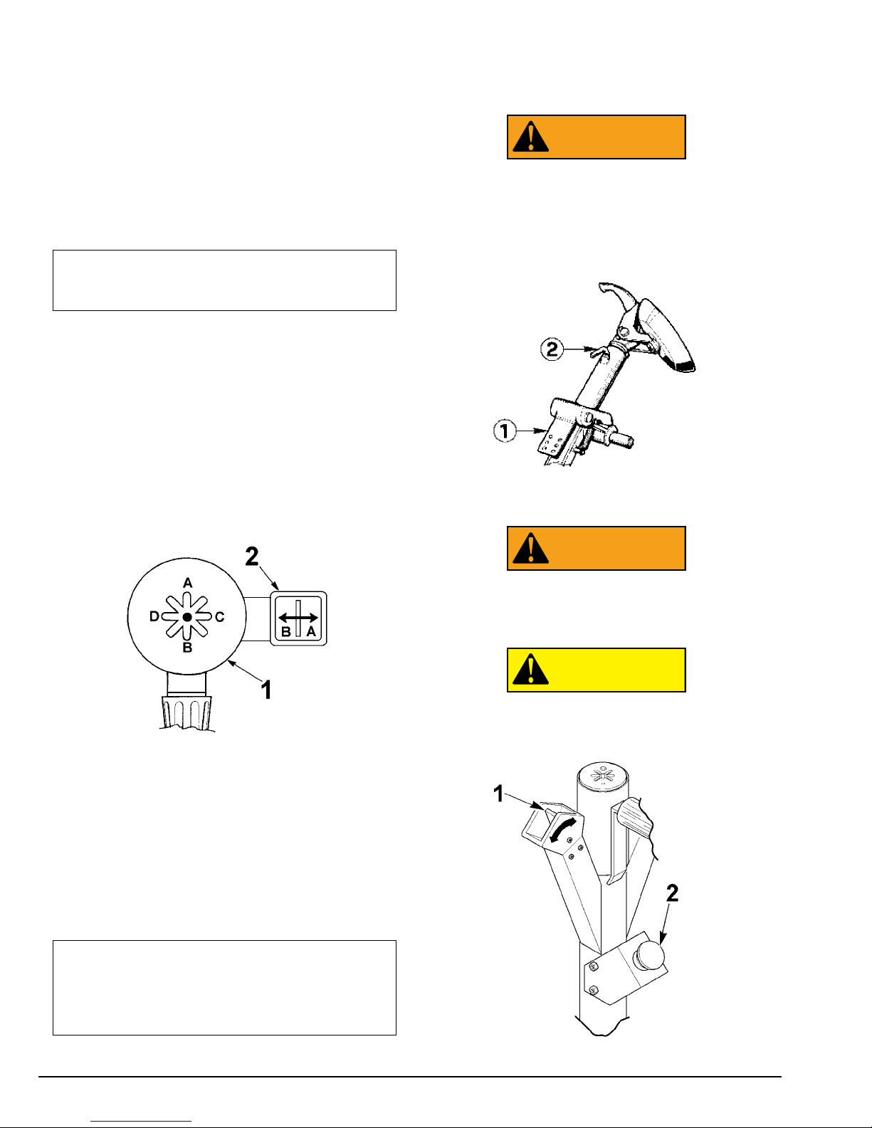
The rotation speed of the chuck has been limited to a
maximum of 8 rpm to prevent dragging or en-trapping
hazards.
There is an emergency button on the portable control
unit.
Important Safety Instructions
Only properly trained personnel should serv-
ice tires on the 9500. Read all safety and
operating instructions thoroughly before
using the tire changer.
ALWAYS
remove all wheel weights and the valve core
to deflate the tire before servicing.
ALWAYS
cover the electric motor and switch box
before hosing down the tire changer. Be sure water
does not enter the motor or switch box.
ALWAYS
disconnect the electric power and air supply
before attempting any maintenance.
ALWAYS
keep all working surfaces clean and free of
tire lube buildup.
ALWAYS
be aware of what each person is and will do
before attempting any two-person operation.
Safety Precautions
A. Before servicing any tires, wheels or rims all per-
sonnel should receive thorough training for the proper
servicing of truck tires, wheels and rims. Consult with
your local city, country state, and national safety and
health administrators to receive clarification of any pub-
lications available governing this serious matter.
B. During the use and maintenance of the machine it
is mandatory to comply with all laws and regulations for
accident prevention.
C. The electric power source must have a ground
cable and the ground cable of the machine (yellow and
green) must be connected to the ground cable of the
power source.
D. Before any maintenance or repairs are accom-
plished the machine must be disconnected from the
electric supply. The unit should only be serviced by a
qualified service technician.
E. Never wear ties, chains or other loose articles
when using, maintaining or repairing the machine. Long
hair is also dangerous and should be kept under a hat.
The user must wear proper safety attire, i.e. gloves,
safety shoes and glasses.
F. Maintain all electric cords in good repair.
G. Keep safety features in place and in working order.
H. Keep working area clean. Cluttered areas invite
accidents.
I. Avoid dangerous environments. Don’t use power
tools or electrical equipment in damp or wet locations,
or expose them to rain.
L. Nobody should be allowed to stand next to or near
the wheel, when mounting/demounting a tire or clamp-
ing a wheel.
M. Keep the work area well lighted.
N. Properly anchor the machine to the floor.
WARNING

iv • COATS 9500Tire Changer
Bead Loosening Safety
NEVER
place any part of your body between the bead
loosener disc and the tire/wheel, severe bodily injury
may result.
NEVER
place anything between the bead loosener
disc and the tire/wheel as damage may result.
NEVER
allow the bead loosener to contact the wheel,
wheel damage may occur.
Demounting & Mounting Safety
NEVER
stand on the working table while demounting
or mounting a tire, as personal injury may result.
ALWAYS
keep hands, feet, and other objects away
from moving parts while the machine in turned on.
ALWAYS
place the narrow bead seat to the outside
when clamping. Failure to demount the tire from the
narrow bead seat side may cause damage to the tire
beads.
ALWAYS
apply an approved rubber lubricant to rim
flanges and both tire beads before demounting or
mounting and seating the beads.
NEVER
use
antifreeze, silicone, or petroleum base lubricants.
ALWAYS
clean and inspect the wheel before servic-
ing.
NEVER
mount a tire on a damaged or rusty wheel.
Wheel damage or rust may cause tire or wheel failure
during inflation. Explosion from failure may result in
severe injury or death of the operator and bystanders.
ALWAYS be sure the bead opposite the tool is in the
drop center before rotating the tire when demounting
or mounting to avoid damage to the tire beads.
Inflation Safety
ALWAYS follow all applicable Local, State, and Federal
Codes, Rules, and Regulations; such as the Federal
OSHA Standard Number 1910.177.
NEVER
seat beads or inflate a tire on the tire changer.
This tire changer is not designed as a safety device or
stand for bead seating or inflation.
ALWAYS
use an approved inflation chamber or infla-
tion cage.
The following safety instructions are for one piece
wheels only. Refer to the manufacturer’s or R.M.A. pro-
cedures for multipiece wheels.
ALWAYS
use an approved inflation chamber or infla-
tion cage equipped with a grip chuck and a remote infla-
tion gauge and valve. DO NOT OVER INFLATE! Tire or
wheel failure during and after inflation may result in an
explosion capable of causing severe injury or death.
ALWAYS
inflate the tire to manufacturer’s recom-
mended cold operating pressure.
NEVER
reinflate a tire that has been run underinflated
or flat without first demounting the tire and checking for
wheel and tire damage.
ALWAYS
inspect the tire interior for loose or broken
cords, cuts, penetrating objects, and other damage to
the carcass. Discard tires that cannot be properly
repaired.
NEVER
rework, weld, heat or braze wheels.
NEVER
strike the tire or wheel with a hammer.
ALWAYS
be sure the tire diameter exactly matches
the wheel diameter.
Tire failure under pressure can be hazardous.
Place the wheel inside an approved inflation
chamber or cage before inflating. Use an
approved remote inflation valve, hose, and
gauge. ALWAYS wear safety goggles for eye
protection. Do not stand beside the wheel or
cage during inflation. Keep hands and other
parts of the body out of the cage during
inflation. Observe the tire pressure fre-
quently. Do not exceed the manufacturer’s
recommended maximum inflation pressure.
Failure to follow these instructions may
cause the tire and rim to separate with
tremendous force, resulting in serious per-
sonal injury or death.
DANGER

COATS 9500Tire Changer • 1
1.0 Introduction
Congratulations on purchasing the COATS®9500
Electro-HydraulicTire Changer.
This tire changer is designed for ease of operation,
safe handling of rims, reliability and speed.
With a minimum of maintenance and care, your tire
changer will provide many years of trouble-free opera-
tion.
Instructions on use, maintenance and operational
requirements of the machine are covered in this man-
ual.
Store this manual in a convenient place for
future reference. Read this manual thor-
oughly before using the machine.
1.1 Use limitations
The COATS model 9500 tire changer is intended to be
used as a device to demount and mount tubeless truck
tires with the following specifications:
MaximumTire Diameter: 90 1/2 inches (2300 mm)
MaximumTire Width : 43 inches (1100 mm)
This device shall be used in the application for which
it is specifically designed. Any other use shall be con-
sidered as improper, and not WITH THE SPECIFICA-
TIONS OF THIS UNIT. In particular, this device is not
suitable to inflate tires. Inflation of tires shall be carried
out in an approved inflation safety cage. The manufac-
turer shall not be considered liable for possible damage
caused by improper, wrong or non-SPECIFIED use.
1.2 Notice
This manual is a part of the product. Read carefully
the warnings and instructions of this manual since they
provide important information concerning safety and
maintenance.
1.3 General Safety Instructions
Any misuse or modification of this device or of its
parts or components not previously authorized by the
manufacturer relieves the manufacturer from any dam-
age consequent or related to the above mentioned
misuse.
No modifications should be made without consulting
COATS®. Removing or bypassing any safety devices or
warning labels of the machine is a violation of the
safety regulations.
The use of this device is allowed only in locations
with no explosion or fire hazards, consistent with state
and local fire codes.
This equipment is designed to use original or manu-
facturer supplied spare parts and accessories only.
The installation shall be carried out only by qualified
personnel and within the scope of the instructions pro-
vided in this manual.
Check for possible dangerous conditions during the
operation of the machine. If such a case exists stop the
machine immediately. In case a defective functioning
condition stop using the machine, immediately and call
the authorized distributor for assistance.
All electrical connections shall be per-
formed by a licensed electrician. All service
must be performed by an authorized service
technician.
1.4 Nomenclature
Before installing and using the tire changer it is sug-
gested that you become familiar with the nomencla-
ture of the machine’s components (fig.1).
Fig.1
1-
8 Position Switch
2-
Chuck Switch
3-
Emergency Stop
4-
Tool Holder Arm
5-
Main Switch
6-
Tool Holder Carriage
7-
Foot Board
8-
Jaws
9-
Self-centering Chuck
10 -
Chuck Arm
11 -
Chuck Rotation Control Pedal
12 -
Mount/DemountTool
13 -
Electric Cabinet
14 -
Tool Holder Arm & Release
WARNING
WARNING

1.5 Specifications
Electro-hydraulic tire changer for tubeless truck tires.
Weight with Standard Acc. 2079 lbs. (945 kg)
Electric Specifications 220VAC, 3Ph, 60Hz, 22A
Hydraulic Motor Power 2 HP (1.5 kW)
Chuck rotation Motor Power 3-4 HP (2.2 - 3 kW)
Chuck Capacity 14” - 56”
Max.Tire Diameter 90 1/2 inches (2300 mm)
Max.Tire Width 43 inches (1100 mm)
Max. ChuckTorque 2268 ft./lbs. (3100 mm)
Clamping Power 13,513 lbs. (60 kN)
Chuck Rotation Speed 4 - 8 rpm
Acoustic Pressure <70dBA
1.6 Dimensions OfThe Machine
Fig.2
1.7 StandardAccessories
#870001418 ShortTireTool
#874004461 LongTireTool
#874002354 Bead Pushing Lever
Fig.3
#874009472 Mounting Clamp (fig.4).
To hold the bead when mounting tires on steel rims.
Instructions for use is in section 5.3.
Fig.4
2 • COATS 9500Tire Changer

COATS 9500Tire Changer • 3
1.8 Optional Accessories
#874021852 Clamp for Light-Alloy Rims (fig.5).
To hold the bead when mounting tires on light-alloy
rims. Instructions for use is in section 5.3.
Fig.5
#874007611 O.T.R. Clamp (fig.6)
Useful when breaking the bead from the rim on multi-
piece wheels (O.T.R.).
Instructions for use is in section 5.6.
Fig.6
#874008257 Protectors for Alloy Rims (fig.7).
Suitable for rims with a center hole of 220 and 280
mm.
Fig.7
#874008264 Protectors for Alloy Rims (fig.8)
Suitable for rims with a center hole of 280 mm only.
Fig.8
#874014974Tubeless Roller (fig.9).
Facilitates mounting and dismounting tubeless tires
up to 13” wide.
Fig.9
#874019161 Extensions for 56” (fig.9/A).
Necessary when clamping rims without flange and
with a diameter exceeding 44”.
Fig.9/A

2.0 Carriage Instructions
The machine is crated in a wooden box of appropriate
strength.
The box is mounted on a pallet.
Handling of the machine must be performed with an
appropriate lifting device (fork lift) (fig.10).
Fig.10
2.1 Uncrating Instructions
Always wear gloves when uncrating the
machine to prevent scratches, abrasions, or
cuts due to the contact with packing mate-
rials.
Uncrate the machine paying attention when removing
the nails or during any other operation which may be
hazardous.
After removing the crate, check for any visible dam-
age to the machine and its components.
If in doubt, call qualified personnel for assistance.
The packing materials (plastic bags, polystyrene, nails,
screws, wood etc.) must be properly disposed of.
Place the above-mentioned materials into a trash con-
tainer and dispose per local regulations.
2.2 InstallationArea
Install the machine in a covered and dry area.
The installation of the machine requires a free space
of at least cm 16’ 5” x 16’ 5” (500cm x 500cm) (fig.11).
Fig.11
Make sure that from the operating position (fig. 11)
the user can see all of the machine and the surround-
ing area.
Only authorized operators of the equipment should
be in the work area. Keep the work area clean and clear
of objects which may create possible hazards.
It is the responsibility of the facility owner to properly
designate work areas and areas where by-standers are
not permitted.
Install the machine on a horizontal floor, preferably
even. Do not install the machine on a sinking or irregu-
lar floor.
In case the machine is installed on a raised floor or on
a service vehicle, the floor must have a capacity of at
least (330 lbs. x sq. ft.). Please contact COATS directly
at 1-800-688-9240 to discuss options and other pre-
cautions that may apply.
The machine must be secured to the floor through
the holes provided in the cabinet. Expansion screws
(1/2” x 4 3/4”), or bolts (1/2” x 3 1/8”) shall be used.
Drill (1/2”) holes in the floor flush with the holes pro-
vided in the cabinet.
Place the lags into the holes drilled in the floor and
move the machine so that the holes of the cabinet are
flush with the holes in the floor.
Tighten the screws to (50 ft. lbs.).
CAUTION
4 • COATS 9500Tire Changer

COATS 9500Tire Changer • 5
3.0 Installation
Instructions
To install the machine proceed as follows:
A. Before raising the machine, ensure that the chuck
is completely closed, that the chuck arm is lowered
and the tool holder carriage is all the way in (Fig.12).
Fig.12
B. Remove the screws that secure the machine to
the pallet.
Lift the machine only with the two lifting lugs with a
belt or rope of appropriate length and strength.
Do not swing the machine when lifted.
Do not cut the remote unit cord when low-
ering the machine to the ground.
3.1 Electric Installation
All electrical connections shall be performed by a
licensed electrician. All service must be performed by
an authorized service technician.
Check on the plate of the machine that the electrical
specifications of the power source are the same as the
machine.
The machine uses 220VAC, 60 Hz, 3Ph, 22 Amp.
Electrical specifications are clearly marked on a label
at the end of the electric cord.
Before connecting the machine to the power source,
check that the power supply has an efficient grounding
system.
Connect the electric cord of the machine with a cor-
rectly rated plug.
There should be less than 1 Ωbetween the ground
pin and earth ground.
Never connect the grounding wire to a live terminal.
Check that the power supply has an automatic circuit
breaker with a differential circuit set at 30 mA.
The electric motor operates in a wide voltage range
(plus 10% - minus 7%) and frequency range (50 or 60
cycles) and has a class of insulation suit-able for hot
and moist climates.
3.2 Motor Rotation Check
Once the machine is hooked-up, turn the machine on
using the on/off switch.
Important:
Ensure that the rotation direction of the
pump is the same as indicated by the arrow on the
motor cover.
If not, reverse any two phase cables on the plug (i.e.
Reverse the brown and the blue cable).
Any damage caused by the non-application
of the above instructions shall not be cov-
ered by the manufacturer and will void the
warranty.
CAUTION
CAUTION
CAUTION
Note:
The outlet installation must be verified by a
licensed electrician before connecting the tire
changer.
Note:
The yellow with green wire in the cord is the
grounding wire.

Operating Instructions
4.0 Controls
Before operating the machine ensure that you thor-
oughly understood the operation and function of all the
controls.
1.To turn the machine on, rotate the ON/OFF switch
to position 1 and press the reset button: The pump
motor starts turning and remains in operation until the
machine is turned off. The power required is minimum
when the hydraulic cylinders are not in use.
2. Press the chuck rotation pedal to the right: The
chuck rotates clockwise. Press the other pedal: The
chuck rotates counterclockwise.
3. Operate the control (#1 fig.13) to position A: The
chuck arm moves upwards.
Operate the control (#1 fig.13) to position B: The
chuck arm moves downward.
4. Operate the control (#1 fig.13) to position C: The
tool holder carriage moves to the right.
Operate the control (#1 fig.13) to position D:The tool
holder carriage moves to the left.
Fig.13
5. Operate the control (#2 fig.13) to position A: The
tool holder arm moves to the right.
Turn the switch to position B: The tool holder arm
moves to the left.
6. By operating the controls in one of the diagonal
positions, the two adjacent movements are achieved
simultaneously. This operation affords considerable
time saving in the intermediate operations, but
requires a little practice.
7.To lift the tool holder arm, depress the pedal (#1 .
14) and hold handle (#2 fig.14).The arm is balanced by
a spring-loaded mechanism and the effort required is
minimum.
If the tool holder arm is not correctly locked
in the working position serious injury may
result to the operator and to the machine.
When locking the arm into working position be sure
to use enough force to ensure a proper lock.The heavy
metal construction can easily absorb the force.
Fig.14
8.To turn the tool remove pin (#2 fig.14).
Be sure that the lock pin is properly fitted.
9. To open and close the chuck, operate the appro-
priate control (#1 fig.15).
When opening the chuck ensure that the
jaws do not contact or hit other parts of the
machine.
Fig.15
CAUTION
WARNING
WARNING
6 • COATS 9500Tire Changer
Note: Turn the machine OFF after every mounting
or demounting operation, if the time before the next
operation is longer than 5 minutes.
Note: If one of the two hydraulic movements
reaches the end of its course, the speed of the other
movement is appreciably reduced: Interrupt the con-
trol engaged and operate only the desired movement
in order to get normal operating speed.

COATS 9500Tire Changer • 7
10. Press the emergency STOP button (#2 fig.15):
This renders all controls inoperative.
Turn the emergency knob counterclockwise and
press the reset button located on the electric cabinet
to resume normal working conditions.
5.0 Mounting and Demounting - General
Precautions
Before mounting a tire on a rim, pay atten-
tion to the following:
A.The rim and all its parts must be clean and in good
condition: If necessary clean and paint it after remov-
ing all wheel-weights, including tape weights inside
the rim.
B. The tire must be clean and dry, without any dam-
age to the bead and the carcass.
C. Replace the rubber valve stem with a new one or
replace the “o” ring if the valve stem is made of metal.
D. If the tire requires a tube or a flap, make sure the
tube is dry and in good condition.
E. Lubrication is necessary to mount the tire cor-
rectly and get a proper centering. Be sure you are
using approved lubricant only.
F. Make sure the tire is the correct size for the rim.
5.1 Locking Rims
Lift the tool holder arm and move the tool holder car-
riage all the way out.
Put the wheel in vertically and roll it on the foot board.
Be sure to use alloy adapters when applicable.
Fig.16
If the wheel is very heavy be sure to use a
suitable external lifting device (i.e. fork lift,
crane etc.).
Close the jaws of the chuck and move the chuck
approximately to the center of the rim. Move the foot
board toward the chuck and move the chuck up-down
while opening the chuck arms until the rim is clamped
properly (fig.17).
Fig.17
CAUTION
Attention!
The drop center of the rim (when it
exists) must be kept towards the outside of the
machine (fig.16).

5.2 DemountingTubelessTruckTires (Up to
13”Wide)
The tubeless truck tires are mounted on drop-center
rims with a conical base. It is possible to demount
these tires simply by pressure, with a proper lubrica-
tion (fig.18).
Fig.18
1. Remove all wheel-weights from the rim. Remove
the valve stem or core and deflate the tire.
2. Position the bead loosener disc or tubeless roller
(option) as shown in fig.19, fig.20.
Fig.19
Fig.20
3. Lift or lower the chuck so that the bead loosener
disc or tubeless roller remains close to the rim edge.
Turn the chuck counterclockwise and at the same time
shift the tool holder carriage step-by-step toward the
inside to demount the tire.
Continue to turn the chuck and lubricate the bead and
the rim liberally with an approved lubricant.
Use only approved lubricants for tires and
wheels.
4. Raise the tool holder arm to the rest position.
5. Movethe toolholder armall thewayin.Lowerthe arm
and secure. Bring the tool in contact with the inner bead.
6. Loosenthe innerbead as describedin point #3above.
CAUTION
8 • COATS 9500Tire Changer

COATS 9500Tire Changer • 9
7. Continue rotating the chuck, moving tool holder
carriage towards the outside until the beads are
demounted from the rim (fig.21 and fig.22)
Fig.21
Fig.22
Ensure that the outer bead slides into the
drop center opposite to the tool, otherwise
the demounting operation is impossible.
8. Move to the front of the tire and hold it with both
hands in the last part of demounting operation to pre-
vent the tire from falling or rolling away out of control
(fig.23).
Fig.23
CAUTION

5.3 Mounting Tubeless Truck Tires (Up to
13”Wide)
1. Liberally lubricate the entire inner surface of the
rim and the tire beads. Attach the mounting clamp
(fig.24) to the outer rim flange with the valve at 11
o’clock and the clamp at 12 o’clock.
Fig.24
If the rim is made of a light-alloy, the rim shape may
not allow the standard mounting clamp to be attached.
In such a case use the light-alloy mounting clamp
(option). The clamp can be used as shown in fig.25 or
26.
Fig.25
Fig.26
2. Move the chuck arm all the way down. Roll the tire
on the foot board and hang it onto the mounting clamp
(fig.27).
Fig.27
3. Lift the chuck arm and position the mounting hook
or tubeless roller approximately 1.5 cm (1/2”) to the
inside of the rim edge and approximately 1.5 cm (1/2”)
away from the rim edge (fig.28).
10 • COATS 9500Tire Changer

COATS 9500Tire Changer • 11
The mounting clamp is at approximately 11 o’clock.
Fig.28
Never use hand pressure to hold the tire
onto the rim as personal injury may result.
4. Turn the chuck clockwise until the tire is com-
pletely mounted (fig.29).
Fig.29
Ensure that the outer bead moves into the
drop center when the clamp is opposite to
the tool.
Stop the chuck before one complete turn is
made to avoid serious damage to the
mounting clamp and to the rim.
Do not inflate the tire on the machine.This
machine is not an inflation device.
For inflation place the wheel in an approved
inflation restraint device. Refer to OSHA
standard number 1910.177.
WARNING
CAUTION
CAUTION
CAUTION

5.4 Demounting Duplex and Supersingle
TubelessTruckTires (Over 13”Wide)
Note: For this operation the mount/demount tool is
required.
1. Loosen the bead of the tire as described in #5.2.1-
5.2.6.
2. For this type of tire it is not possible to demount
both beads at the same time with the roller as
described in #5.2.7.
Engage the hook of the mount/demount tool
between the bead and the rim.
3. Lift the chuck arm enough to clear the hook 1” - 1
1/2” from the rim flange. Move the mount/demount
tool towards the outside. This will allow you to place
the long bar in between the bead and the rim flange for
necessary prying (fig.30).
Fig.30
4. Rotate the chuck counterclockwise until the outer
bead is completely demounted (fig.31).
Fig.31
5. Demount the inner bead with the bead breaker
disc, as described in #5.2.7. (fig.32).
Fig.32
5.5 Mounting Duplex And Supersingle
TubelessTruckTires (Over 13”Wide)
1. Hang the inner bead of the tire on the mounting
clamp (fig.33).
Fig.33
2. Position the mounting hook about 3/4” (1.5 cm) to
the inside of the rim edge and 1/2” (1 cm) away radi-
cally.
12 • COATS 9500Tire Changer

COATS 9500Tire Changer • 13
3. Rotate the chuck clockwise. Normally less than
1/4 of a revolution is sufficient to mount the first bead
(fig.34).
Fig.34
4. Re-attach the mounting clamp to the rim flange
with the valve forward of the mounting clamp (fig.35).
Fig.35
5. Rotate the chuck clockwise until the tire is com-
pletely mounted.
Ensure that outer bead descends into the drop center
when the clamp is opposite to the mount/demount
tool (fig.36).
Fig.36
Never use hand pressure to hold the tire
onto the rim.
Stop the chuck before one complete turn is
made to avoid serious damage to the
mounting clamp and to the rim.
Do not inflate the tire on the machine.This
machine is not an inflation device.
For inflation place the wheel in an approved
inflation restraint device. Refer to OSHA
standard number 1910.177.
WARNING
CAUTION
WARNING

5.6 Demounting Tires From Multi-Piece
Rim/WheelAssemblies (TubeTypeTires)
The multi-piece rim/wheel assembly can be in two or
more pieces (fig.37).
Fig.37
1. Remove all wheel-weights from the rim. Remove
the valve stem or core and deflate the tire completely.
2. Position the tool close to the rim edge (fig.38).
When the lock ring is stuck to the tire bead, (on the
O.T.R. tires) to loosen the bead, it is necessary to hold
the ring to the rim with the appropriate clamp
#874007611 (optional accessory).
Fig.38
3. Turn the chuck counterclockwise and loosen the
bead as described in #5.2.1.-5.2.3. Do not lubricate.
4. To remove the lock ring, squeeze one edge with
the proper bar and place the bead loosener disc as
shown in fig.39.
Fig.39
5. Turn the chuck clockwise (or counterclockwise)
until the lock ring is completely removed.
No one should stand in front of the wheel
when removing the lock ring.
Continue to demount all components of the rim man-
ually or with the disc tool.
6. When loosening the inner bead be sure not to
damage the valve stem (fig.40).
Fig.40
WARNING
14 • COATS 9500Tire Changer

COATS 9500Tire Changer • 15
5.7 Mounting Tires Onto Multi-piece
Rim/WheelAssemblies
1. Roll the tire on the foot board (the tube and flap
must be in place).
Note:
O.T.R. tires and rims are very heavy and an out-
side lifting tool may be required.
For tube type only, the valve should be placed at 12
o’clock, for easier mounting.
2. Slide the tire onto the rim with the foot board or
with the bead loosener disc, if necessary.
3. Mount all the assembly components.
4. Engage one edge of the lock ring in its seat and
complete the mounting process with the bead
loosener disc.
In the initial mounting phase hold the rim edge in its
seat with a bar (fig.41).
Fig.41
Do not inflate the tire on the machine.This
machine is not an inflation device.
For inflation place the wheel in an approved
inflation restraint device. Refer to OSHA
standard number 1910.177.
5.8 Demounting Tractor and O.T.R. Wheels
With One-Piece Rims
These wheels may be tube-type or tubeless.The rim
has a slightly conical surface and a very high rim flange
(fig.42) which does not allow you to demount the tire
by simple pressure from the roller as described in
@5.2.
Fig.42
1. Remove all wheel-weights from the rim. Remove
the valve stem or core and deflate the tire completely.
2. Place the disc tool next to the rim edge and
loosen tire inner bead.
3. Loosen the outer bead in the same way, taking
care not to damage the valve stem (fig.43).
Fig.43
4. Lubricate both beads and the rim surface (fig.44).
Fig.44
WARNING

5. Place the hook tool between bead and rim
(fig.45).
Fig.45
6. Lift the chuck arm to move the hook tool away
from the rim edge (1” or 2-3 cm).
Move the tool towards the outside to apply the long
tire bar (fig.46).
Fig.46
7. Turn the chuck counterclockwise until the outer
bead is completely demounted (fig.47).
Fig.47
8. If the tire is tube-type, push the valve stem to-
wards the inside of the rim.
9. Lift the tool holder arm to the rest position.
Shift the tire from the rim, moving the tool holder car-
riage towards the outside:This will make it much eas-
ier to remove the tube (fig.48).
Fig.48
16 • COATS 9500Tire Changer
TireTool
Table of contents
Other Coats Tools manuals
Popular Tools manuals by other brands

Sioux Tools
Sioux Tools ST2L1410 Instructions-parts list

Triton
Triton AWA200 Operating and safety instructions

Canon
Canon Racer 538 Wren Assembly instructions

ReelCraft
ReelCraft RT Series operating instructions

Valley Industries
Valley Industries MHR-M owner's manual

Hitachi
Hitachi SV12SF - 4-3/8" Palm Grip Orbitalsander 1.4Amp 28... instruction manual