SPX RADIODETECTION 6100-Cu User manual

6100-Cu
Multifunction Phone Network
Analyser and Copper Tester
Operation manual
90/6100-CU-OPMAN-ENG/01

6100-Cu Multifunction Copper Tester Operation Manual
2 © 2020 Radiodetection Ltd
inside front cover

6100-Cu Multifunction Copper Tester Operation Manual
© 2020 Radiodetection Ltd 3
Contents
Preface.........................................5
1.1 Before you begin..........................................5
1.2 Important notices.........................................5
1.3 Training .......................................................5
Introduction.................................6
2.1 About this manual........................................6
Additional documentation......................................6
2.2 About the 6100-Cu.......................................6
2.3 Product description......................................6
2.4 Key Features and Benefits...........................6
2.5 Typical Applications.....................................6
Using the 6100-Cu.......................7
3.1 Cable Connections ......................................8
3.2 Technical specifications...............................8
Safety Information ......................9
4.1 Equipment Ratings ......................................9
Getting Started with the 6100-
Cu................................................................10
5.1 Turning the Unit On/Off..............................10
5.2 Using Menus and Keypad..........................10
5.3 Keypad......................................................11
5.4 Using Screenshot Capture.........................11
Setting Up the 6100-Cu.............12
6.1 Home.........................................................12
6.2 System Settings.........................................12
6.3 Display and Language...............................12
6.4 Remote Display .........................................13
6.5 Date and Time...........................................14
6.6 Battery Info................................................15
6.7 Software Options.......................................16
6.8 Information.................................................16
6.9 Upload Setup.............................................17
6.10 Wi-Fi Test................................................20
6.11 Comms Setup..........................................21
Setting Up Copper Tests..........23
7.1 Copper Test Main Menu ............................23
7.2 Test Configuration .....................................23
7.3 Setup.........................................................27
7.4 Phone Book...............................................28
7.5 Dialer Function...........................................31
7.6 Cable Book................................................34
7.7 Application Settings...................................38
7.8 Test Lead Compensation...........................42
7.9 FED Control...............................................43
7.10 Saving Results.........................................47
Reading Saved Copper Test
Results........................................................49
8.1 Result Manager.........................................49
8.2 Results Summary......................................49
8.3 Result Manager Menu...............................49
8.4 Upload.......................................................51
8.5 Export........................................................52
8.6 Delete........................................................53
Multimeter Tests....................... 54
9.1 Multimeter Main Page ...............................54
9.2 Voltage......................................................55
9.3 Current......................................................57
9.4 Resistance................................................59
9.5 Resistive Balance......................................61
9.6 Isolation.....................................................63
9.7 Capacitance/Opens...................................65
9.8 Station Ground..........................................67
9.9 Stressed Balance......................................69
SmartR Features..................... 72
10.1 Pair Detective..........................................72
10.2 Pair Detective Result Details...................77
10.3 FaultMapper............................................77
Noise Tests ............................. 82
11.1 Noise Tests Main Page...........................82
11.2 VF Noise.................................................82
11.3 Power Influence ......................................84
11.4 VF Impulse Noise....................................85
11.5 WB PSD Noise........................................87
11.6 WB Impulse Noise...................................90
11.7 NEXT ......................................................92
Frequency Tests..................... 98
12.1 Frequency Tests Main Page....................98
12.2 VF/AC Balance........................................98
12.3 WB Balance ..........................................101
12.4 WB Attenuation..................................... 104
12.5 Return Loss...........................................107
12.6 Load Coils.............................................110
12.7 Locator Tone.........................................112
12.8 TX/RX Tone ..........................................113
12.9 RX Tone with FED................................. 114
TDR........................................ 118
13.1 Continuous............................................118
13.2 xTalk TDR............................................. 123
13.3 Cable Setup..........................................125
13.4 Load Trace............................................126
13.5 Result Details........................................126
13.6 TDR Profile Details................................128
RFL ........................................ 129
14.1 Single Pair.............................................129
14.2 Separate Good Pair...............................130
14.3 K-Test ...................................................131
14.4 RFL Cable Setup...................................133
14.5 Result Manager.....................................133
14.6 Result Details........................................134

6100-Cu Multifunction Copper Tester Operation Manual
4 © 2020 Radiodetection Ltd
Copper Auto Tests ............... 136
15.1 Menu......................................................136
15.2 POTS Auto Test.....................................136
15.3 User Auto Test.......................................138
15.4 Result Details.........................................146
15.5 Profile Details.........................................146
Maintenance.......................... 150
16.1 General Maintenance.............................150
16.2 Recalibrating the Unit.............................150
16.3 Battery...................................................150
16.4 Recycling and Disposal..........................151
Troubleshooting................... 153
17.1 Solving Common Problems....................153
17.2 LED Statuses.........................................154
17.3 Transportation........................................154
Software License Agreement
(“Agreement”) ......................................... 155
18.1 DEFINITIONS........................................155
18.2 PROPRIETARY RIGHTS.......................156
18.3 LICENSE GRANT..................................156
18.4 LICENSE RESTRICTIONS....................157
18.5 RESERVED RIGHTS.............................157
18.6 COOKIE AND PRIVACY POLICY..........158
18.7 AUDIT....................................................158
18.8 SUPPORT .............................................158
18.9 CONFIDENTIAL INFORMATION...........158
18.10 LIMITED WARRANTY AND EXCLUSIVE
REMEDY..............................................159
18.11 DISCLAIMER.......................................159
18.12 LIMITATION OF LIABILITY..................159
18.13 TERM AND TERMINATION.................160
18.14 GENERAL............................................160

6100-Cu Multifunction Copper Tester Operation Manual
© 2020 Radiodetection Ltd 5
Preface
1.1 Before you begin
Thank you for your interest in Radiodetection’s 6100-
Cu Multifunction Phone Network Analyzer and Copper
Tester.
Please read this user manual in its entirety before
attempting to use the 6100-Cu system as it contains
many important safety notices and warnings.
Radiodetection products, including this manual, are
under continuous development. The information
contained within is accurate at the time of publication;
however, the 6100-Cu, this manual and all its contents
are subject to change.
Radiodetection Limited reserves the right to modify the
product without notice and some product changes may
have taken place after this user manual was published.
Contact your local Radiodetection dealer or visit
www.radiodetection.com for the latest information
about the 6100 product family, including this manual.
1.2 Important notices
Read this manual in its entirety before attempting to
operate the 6100-Cu. Note all safety notices in the
preface and throughout this manual.
Ensure that you have read and understood the safety
notices in Section 4 Safety Information.
WARNING: Failure to comply with safety warnings
can cause serious injury or death.
CAUTION: Failure to comply with safety cautions can
result in damage to equipment or property.
This equipment shall be used only by qualified and
trained personnel, and only after fully reading this
Operation Manual.
WARNING: Direct connection to live conductors is
POTENTIALLY LETHAL. Direct connections
to live conductors should be attempted by
fully qualified personnel only using the
relevant products that allow connections to
energized lines.
You are responsible for determining whether the
conditions are suitable for using this device. Always
carry out a risk assessment of the site to be inspected.
Follow your company and national safety procedures
and or requirements when operating this equipment in
any environment or workplace. If you are unsure what
policies or procedures apply, contact your company or
site’s occupational health and safety officer or your
local government for more information.
Do not use this equipment if you suspect that any
component or accessory is damaged or faulty.
Use authorized accessories only. Incompatible
accessories may damage the equipment or give
inaccurate readings.
Keep this equipment clean and arrange for regular
services with an authorized Radiodetection service
center. More information can be found in the Appendix
or from your local Radiodetection representative.
Headphone use: you need to remain alert to traffic and
other hazards that are normally heard outdoors. Always
turn the volume down before plugging headphones into
an audio source and use only the minimum level,
necessary to take your measurements. Excessive
exposure to loud sounds can cause hearing damage.
Do not attempt to open or dismantle any part of this
equipment unless directed specifically by this manual.
Doing so may render the equipment faulty and may
void the manufacturer’s warranty.
You are responsible for determining whether you
consider the measurement results to be valid and for
any conclusions that are reached or any measures that
are taken as a result thereof. Radiodetection can
neither guarantee the validity of any measuring results
nor can we accept liability for any such results. We are
on no account able to accept liability for any damage
which may be caused as a consequence of the use of
these results. Please see the Standard Warranty Terms
enclosed with the product for further information.
1.3 Training
Radiodetection provides training services for most
Radiodetection products. Our qualified instructors will
train equipment operators or other personnel at your
preferred location or at a Radiodetection location.
For more information go to www.radiodetection.com or
contact your local Radiodetection representative.

6100-Cu Multifunction Copper Tester Operation Manual
6 © 2020 Radiodetection Ltd
Introduction
2.1 About this manual
This manual provides copper network installation and
repair professionals with comprehensive operating
instructions for the 6100-Cu test system. Before
operating the 6100-Cu system it is very important that
you read this manual in its entirety, noting all safety
warnings, cautions and procedures.
Additional documentation
The full product specification and related manuals are
available to download from
www.radiodetection.com.
2.2 About the 6100-Cu
The 6100-Cu is a handheld device designed to qualify
and troubleshoot the copper-loop plant by using
pass/fail-driven automated functionalities.
The unit also verifies the location of faults during the
installation and repair of voice and DSL circuits.
For more information, including available accessories,
please visit
www.radiodetection.com
2.3 Product description
The 6100-Cu Test Set is housed in an aluminum
enclosure with rubber over mold, which makes it ideal
for field use. Its display is a back-lit LCD featuring 480 x
800 resolution. A membrane keypad mounted on the
face of the unit features a 14-button keypad used to
operate the test set. An external keyboard and mouse
can also be used.
2.4 Key Features and
Benefits
User-defined automatic testing
Single-ended copper testing –no remote device
required
Color display with graphical analysis
Battery powered
Rugged and weatherproof handheld unit
Touchscreen with stylus
Compatible with Teletech TS125 or Viavi UFED IIB
Remote Far End Device (FED) for remote control
circuit change
2.5 Typical Applications
Automatic Pair Quality Test toward remote test
head or far end device (FED)
Multimeter tests
Noise tests including power influence and PSD
Frequency tests including balance, load coils,
and tracing tone
Fault location tests including TDR and RFL
SmartR features including Pair Detective and
FaultMapper
Configurable pass/fail results for automated
testing

6100-Cu Multifunction Copper Tester Operation Manual
© 2020 Radiodetection Ltd 7
Using the
6100-Cu
The 6100-Cu is tested for IEC IP54 compliance which
means that it is not affected by dust or water splashing
against the enclosure from any direction. This
protection is only valid when both side doors are
properly closed. If the equipment is used in a manner
not specified by the manufacturer, the protection
provided by the equipment may be impaired.
The 6100-Cu is equipped with a series of interfaces:
Fig. 3.1: 6100-Cu connections –left view
Fig. 3.2: 6100-Cu connections –right view
Fig. 3.3: 6100-Cu connections –top view
Fig. 3.4: 6100-Cu connections –back view
Note: The 6100-Cu enclosure may become warm
during normal use.
USB Host Port
USB Client Port
Door
Head Set Jack (2.5mm)
SD Card (not used)
USB Client Port
Stylus
DC Power
Door
Battery door
Stylus
Screws
Screws
Touchscreen
Power LED
Battery LED
Speaker

6100-Cu Multifunction Copper Tester Operation Manual
8 © 2020 Radiodetection Ltd
3.1 Cable Connections
The graphics below show the connectors on the 6100-
Cu device.
Fig. 3.5: 6100-Cu connections –end view
Note: When connecting a DSL cable to the WAN port,
use the RJ-45 plug end of the cable provided
with the unit. There is a 1500 V maximum
transient voltage on telecom ports. Basic
insulation is needed for external telecom circuits.
Fig. 3.6: 6100-Cu connection identification
WARNING! A 50 to 500 V limited power source
may be present on connector T/R/G (A/B/E),
T1/R1/G (A1/B1/E) when the unit is testing
isolation resistance. Use with caution.
WARNING! These connections are intended for
the express purpose of electrical testing of
common telephone line conductors, within
the ranges specified in the Technical
Specifications found on the Radiodetection
Web site. The device is not intended to be
used on telephone lines having voltages
greater than 280 VAC or 400 VDC, and it is
also not intended to be used on power
distribution circuits.
CAUTION: The unit is protected against damage caused
by fault voltages that may be present on lines
under test. Do not connect the unit if the
maximum expected fault voltage is greater
than 500 volts.
3.2 Technical specifications
Please see the separate Technical Specification
document, available at www.radiodetection.com
Ground
terminal
Primary tip/A and
ring/B connectors
Secondary tip/A
and ring/B
connectors
WAN port
Primary Tip/A wire of phone line
Primary Ring/B wire of phone line
Shield of phone line
Secondary Tip/A
wire of phone line
Secondary Ring/B
wire of phone line

6100-Cu Multifunction Copper Tester Operation Manual
© 2020 Radiodetection Ltd 9
Safety
Information
WARNING. The use of controls, adjustments and
procedures other than those specified
herein may result in exposure to hazardous
situations or impair the protection provided
by this unit.
WARNING. If the equipment is used in a manner not
specified by the manufacturer, the
protection provided by the equipment may
be impaired.
WARNING. Use only accessories designed for your
unit and approved by Radiodetection. For a
complete list of accessories available for
your unit, refer to its technical specifications
or contact Radiodetection.
IMPORTANT
When you see the following symbol on your unit,
make sure that you refer to the instructions provided in
your user documentation. Ensure that you understand
and meet the required conditions before using your
product.
IMPORTANT
Other safety instructions relevant for your product are
located throughout this documentation, depending on
the action to perform. Make sure you read them
carefully when they apply to your situation.
Electrical Safety Information
The AC adapter/charger provided with this unit is
specifically designed to work with your 6100-Cu.
WARNING.
Only use the AC/DC adapter/charger indoors.
Only use with a Class II AC/DC adapter, power
limited output.
On the AC/DC adapter, replacing detachable
mains supply cords with inadequately rated
cords, may result in overheating of the cord
and create a fire risk.
The adapter shall have the appropriate safety
mark (e.g. UL, CSA, TUV, CE, etc.) that is
acceptable to the authorities in the country
where the equipment is to be used.
CAUTION. When using the 6100-Cu while connected to
the AC/DC adapter/charger, make sure you
do not position the equipment so that it is
difficult to disconnect the adapter/charger
from the AC mains.
WARNING. Only use accessories that meet
Radiodetection specifications.
4.1 Equipment Ratings
Temperature
Operation
0 °C to 40 °C (32 °F to 104 °F)
Storage
–40 °C to 70 °C (–40 °F to 158 °F)
Relative humidity a
6100-Cu
≤ 95 % non-condensing
AC adapter
0 % to 80 % non-condensing
Maximum
operating altitude
3000 m (9843 ft)
Pollution degree
2 (when plugged to AC mains) b
3 (when operated from
batteries) c
Overvoltage
category
II
Input power d
6100-Cu
9-24 V; 18 W; 1.67 A
AC adapter
100 - 240 V; 50/60 Hz; 0.7 A
a. Measured in 0 °C to 31 °C (32 °F to 87.8 °F) range,
decreasing linearly to 50 % at 40 °C (104 °F).
b. For indoor use only.
c. Equipment is normally protected against exposure
to direct sunlight, precipitations and full wind
pressure.
d. Not exceeding ± 10 % of the nominal voltage.

6100-Cu Multifunction Copper Tester Operation Manual
10 © 2020 Radiodetection Ltd
Getting
Started with the 6100-
Cu
5.1 Turning the Unit On/Off
When you turn the unit on, you may use it immediately
under normal conditions. When the unit is turned off, it
keeps the following parameters in its internal memory:
Setup including application settings, phone and
cable books, and test lead characteristics.
Profiles consisting of:
oTest parameters
oUser-defined thresholds
Note: Save the current profile before turning the unit
off, or else any changes will be lost. See To
save a profile, use one of the following function
keys: for more information.
Regional, LCD, and energy-saving settings
Test results saved internally vs. USB
There are two ways to turn off the 6100-Cu:
Suspend: the next time you turn your unit on,
you will quickly return to your work
environment.
Shutdown: completely cuts power to the unit;
the unit will perform a complete restart routine
the next time you use it. You should perform a
shutdown if you do not intend to use your unit
for a few hours or more.
To turn the unit on:
Press to start. The unit initializes for a few seconds
and displays the Home pane.
To enter suspend mode:
Press for about 2 seconds. The 6100-Cu will stay
in suspend mode for 2 hours. After which it will
automatically shut down. This prevents complete
battery discharge and ensures maximum battery
performance.
To perform a shutdown:
Hold down for at least 4 seconds. The shutdown
process starts.
Note: In both previous cases, if the power adapter is
connected, the 6100-Cu will simulate either a
fake suspend or fake shutdown in order to
facilitate the charger.
Note: If you hold down for 12 seconds or more, the
6100-Cu may reset the date and time to incorrect
values. Once the unit is powered back on, an
Invalid Date and Time dialogue box will pop up
displaying The unit date and time are probably
invalid. (1/1/2006 12:00:25 PM). Please update
the date and time in Date and Time to ensure
the delivery of all the functionality the unit has to
offer.
5.2 Using Menus and Keypad
You can access various tools from the keypad or menu.
Menu options may differ depending on your unit
configuration.
Home menu is where you can access Copper tests or
System Settings. Each test has a sub menu.
To navigate through the items, use the arrow
keys.
To confirm a choice or enter a menu,
press .
To cancel an action or test, or return to the
previous item or pane, press .
Press once to return to the Main test menu
or twice to return to the Home page.
Note: Pressing while a test is running will also stop
the test and return to the main menu screen.
Note: You can also select an option directly by pressing
the function keys corresponding to the on-screen
buttons at the bottom of the screen.

6100-Cu Multifunction Copper Tester Operation Manual
© 2020 Radiodetection Ltd 11
5.3 Keypad
Power button on the lower left side of the unit is
used to power the unit on and off.
Arrow Keys navigate the screen to access and
modify parameters.
Function Keys activate the corresponding on-
screen function button.
Home button brings you to the Copper Main
page of the 6100-Cu or to the Home page.
5.4 Using Screenshot
Capture
Using the Home/Help button, you can take a
screenshot of the current page display. If screenshots
are Enabled, you will have to select No in the popup
message before accessing the onboard help. (See
below.)
Screenshot Capture
To take a screenshot:
Press and hold the Home/Help button to capture the
current page and save it with filename
screenshot_ddmmyyyy_hhmmss
where ddmmyyyy is 2-digit day, 2-digit month, 4-digit
year; and hhmmss is 2-digit hour, 2-digit minute, and 2-
digit second.
Note: The date and time value format is dependent on
the format selected in System Settings \ Date
and Time.
Screenshots can be Enabled or Disabled from
the System Settings \ Display and Language
page.
If Enabled, press and hold the ?key to
capture a screenshot on any page.
A popup message is displayed saying
Screenshot captured, Press “Yes” to save
or “No” to continue to Help. Pressing No will
also discard the screenshot.
Note: If you selected USB as the screenshot file
location and no USB is connected to the 6100-
Cu, the following popup message is displayed:
Screenshot not saved, Insert USB and press
“Yes” to save it or press “No” to continue to
Help.
Disabling Enable Screenshots will take you to
the onboard help page when pressing and
holding the ?key, as previously described.
Onboard Help
Onboard help is available at any time. Most test
operations pause while you view help, but will resume
automatically when you exit help.
To access help about the current function at any
time:
Press and hold the ?key.
Function
keys
Arrow keys
Power
Home/
Help
Start/
Stop
test
Enter
Back

6100-Cu Multifunction Copper Tester Operation Manual
12 © 2020 Radiodetection Ltd
Setting Up
the 6100-Cu
6.1 Home
Home presents the main menu page which allows you
to navigate between Copper Test and System
Settings using the left/right arrow keys on the keypad.
Press to bring up the sub-menu of the selected icon:
Copper Test opens the Copper Main menu
displaying the copper qualification testing
applications.
System Settings allow you to set the
parameters of the unit such as language, date
and time, and battery info. You can also view
installed options, and software and hardware
revision information. Plus, System Settings
provides access to Upload Setup.
6.2 System Settings
System Settings presents a menu of items to setup
the unit.
Display and Language provides the setup for
backlight, information on the title bar, language
choice, and Touchscreen Calibration.
Date and Time sets the date, time and format.
Battery Info displays the battery status and
measurements, and allows you to set the
power schemes.
Software Options allow you to enable/disable
purchased feature options.
Information displays information About
Radiodetection and unit details pertaining to
hardware/software/ product info.
Upload Setup allows you to enable and select
an upload method using the following function
keys:
Upload Enable
FTP Setup
Wi-Fi Setup
Ethernet Setup
To navigate between the system settings:
1. Press the up/down left/right arrow keys on the
keypad to select an icon.
2. Press to confirm your selection.
6.3 Display and Language
To fit your work environment, you may adjust the LCD
brightness, display the time and ActiveSync, and
change the display language. Plus, you can Enable
Screenshots which uses the Home/Help button. The
values are kept in memory when you turn the unit off.

6100-Cu Multifunction Copper Tester Operation Manual
© 2020 Radiodetection Ltd 13
Note: The LCD Backlight consumes battery power;
more brightness results in more power
consumption.
To adjust the display settings:
1. From , select System Settings, and then
Display and Language.
2. Use the up/down arrow keys to select the
setting to change.
3. Press to select.
By using the up/down arrow keys, you can
switch between preset brightness levels in the
Backlight item. Press to confirm.
To display the time and ActiveSync in the title
bar, enable the item.
Press after your selection to confirm.
Use the up/down arrow keys to navigate
between the available languages, then press
to select. You will be prompted to restart
your unit.
To set which Home page the unit defaults to
when pressing , highlight Start 6100-Cu
using: and select from the list.
Touchscreen Calibration. To calibrate the
touchscreen, press/tap/click the button to open
a popup window and select Yes or No. This
screen will automatically display during power
up, if calibration was never conducted and the
data file is not available in memory.
To Enable Screenshots, select Enabled
(default), then the Screenshot file format in
either JPG (default) or GIF, and where you
would like to Save Screenshot to: USB
(default) or FTP.
oIf USB, the image is saved to a directory
called \\6100\Screenshots on the USB
memory device. If the directory does not
exist, create it on the root directory of the
USB memory device.
Note: If you selected USB as the screenshot file
location and no USB is connected to the 6100-
Cu, the following popup message is displayed:
Screenshot not saved, Insert USB and press
"Yes" to save it or press "No" to continue to
Help.
oIf FTP, the image is saved locally to
\\DATA\6100\Copper\UploadResults.
From Result Manager\Upload\Upload
Location, select FTP to enable uploading
screenshot images to the FTP server. If
you select USB as the Upload Location,
the image is uploaded to Removable
Disk\6100\Screenshots.
Note: FTP is available only if you have the FTP Result
Upload option listed in System
Settings\Software Options\Platform Options.
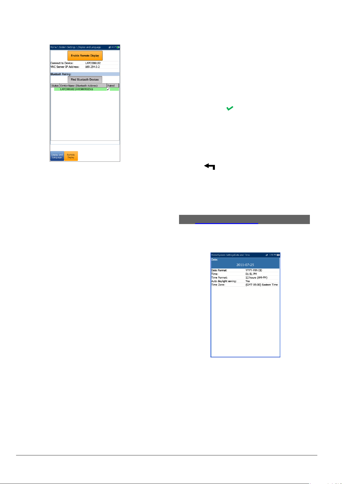
6.4 Remote Display
The Remote Display function allows you to connect the
6100-Cu to your computer remotely, using PC
TightVNC or RealVNC client application, and a
Bluetooth or USB connection.
Enable Remote Display button starts the
Remote Display connection. Once the
connection is setup successfully and the
remote display server starts, the button
changes to Stop Remote Display until the
connection is dropped.
Connect to Device allows you to select a
Bluetooth device that has been paired
successfully or a USB Connection. A
connection icon is displayed in the menu bar if
the setup is successful. If you select None,
then the Enable Remote Display button is
disabled.
6100-Cu Multifunction Copper Tester Operation Manual
14 © 2020 Radiodetection Ltd
Note: The USB Connection for Remote Display uses
RNDIS protocol and the ActiveSync will not be
functional when this USB connection is active.
VNC Server IP address displays one of the
following server IP addresses:
ofor a USB Connection, 169.254.0.1
ofor a Bluetooth connection, 169.254.0.2
ofor None, N/A
Bluetooth Pairing
oFind Bluetooth Devices button
searches for and lists all discoverable
Bluetooth devices. The list also displays
all the device names that were
previously paired with your 6100-Cu,
whether or not a Bluetooth signal is
currently present.
oStatus displays a Bluetooth symbol if the
device is connected.
Device Name (Bluetooth Address) displays
the name of the device and its Bluetooth
address.
A third, right-hand column displays a
checkmark if the device is Paired.
Note: Use only a Radiodetection certified Bluetooth
dongle.
To initiate remote display:
1. Connect the Bluetooth Dongle or USB
Connection to a USB port on the 6100-Cu.
2. Select the Connect to Device and press the
up arrow key to highlight and press the Enable
Remote Display button.
OR
3. Press the down arrow key to highlight and
press the Find Bluetooth Devices button to
search for available Bluetooth devices.
4. Press the down arrow key to highlight the list
box and press to get into the list.
5. In the list, press the up/down arrows to select a
device to pair.
6. Follow the instructions in the pop-up dialog
boxes. Only one device can be paired at a time
in the 6100-Cu.
7. Once you have connected to your device,
press to come out of the list.
8. Return to step #2 above to select your
Bluetooth device and establish the VNC
connection.
6.5 Date and Time
When saving results, the unit also saves the
corresponding Date and Time.
Date allows you to enter the date according to
the following formats:
oyyyy-mm-dd
odd-mm-yyyy
omm-dd-yyyy
The Time Format can be set according to the
12- or 24-hour formats.

6100-Cu Multifunction Copper Tester Operation Manual
© 2020 Radiodetection Ltd 15
You can also modify the Time Zone and
enable an option so that your unit automatically
adjusts the time for the daylight saving period.
To set the date and time:
1. Press , select System Settings, and then
Date and Time.
2. Use the up/down arrow keys to select any of
the date or time settings.
3. Press to enable the modification controls.
a. For the Date and Time, an edit screen
is displayed with descriptive function
keys.
b. Use the arrow keys to modify the
number values, then press to confirm
the change and go back to the
previous screen.
c. If 12 hours (AM-PM) is selected, when
setting the Time in the edit screen,
toggle the AM/PM function key for the
desired period of the day. Press
to go back to the previous screen
without saving the new value.
d. For the Time Format, Auto daylight
saving and Time Zone values, use the
arrow keys to select the desired value,
then press to confirm the change.
6.6 Battery Info
You can set your unit to automatically switch to
suspend mode independently for the battery or DC
power modes.
This is useful for example if you want to save battery
power but do not want to be hindered by unwanted
switches between modes when using DC power.
Power off completely shuts down the unit’s
power.
Power suspend puts the unit in sleep mode;
you can wake up the system by pressing .
Note: If you hold down for 12 seconds or more, the
6100-Cu may reset the date and time to incorrect
values. Once the unit is powered back on, an
Invalid Date and Time dialog box will pop up
displaying The unit date and time are probably
invalid. (1/1/2006 12:00:25 PM). Please update
the date and time in System Settings/Date and
Time to ensure the delivery of all the functionality
the unit has to offer.
DC IN/BATTERY Idle timeout allows you to
set the time duration for the unit to idle (no
keys pressed or test being run) before turning
off the LCD.
DC IN/BATTERY suspend timeout allows you
to set the time duration for the unit to enter
sleep mode.
Note: Setting the DC IN suspend timeout to the lowest
value and not to Never ensures the unit enters
suspend mode while the charger is connected.
Battery charging time is quickest when the unit is
in suspend mode.
Power Save Mode is either Disable/Enable.
When enabled, BATTERY Idle timeout and
BATTERY suspend timeout are set to 5 min,
Backlight to 50 %, and Modem Power OFF
(including the unit) to Immediately. The
selections are limited and the following warning
message will popup:
Power Save mode is enabled. High Voltage
Monitoring is active only while the test is in
progress.
The Default power scheme settings are:
LCD backlight turns off after system idles (no
keys pressed) for 10 min.
Unit switches to suspend mode after timeout:
10 min.
Power Save Mode is Disable requiring you to
go to this page to see what will be changed
before enabling it.
The chart displays the following battery measurements:
capacity, current, and voltage. Battery Status indicates
the current power level, as a percentage, for the
battery.

6100-Cu Multifunction Copper Tester Operation Manual
16 © 2020 Radiodetection Ltd
To change the power scheme settings:
1. Press , select System Settings, and then
Battery Info.
2. Under DC IN or BATTERY, use the arrow keys
to select Idle/suspend timeout modes. Press
to view the list of available choices or use
the left/right arrow keys.
3. Select a new value, then press to confirm
the choice. Repeat for the other modes as
needed.
6.7 Software Options
To activate a newly purchased option key on your
6100-Cu, please contact Radiodetection. The unit may
require returning to Radiodetection.
Copper Options
This screen lists all the Copper Configured Options
that are present on the unit. Possible options are as
follow:
TDR
RFL
FaultMapper
Pair Detective
Wideband Testing
Near End Crosstalk
High Voltage Isolation Resistance
Stressed Balance Test
Far End Device Test Control
Return Loss
ADSL+ and VDSL2 Data Rate Prediction
VDSL2-35b Data Rate Prediction
UFED Control
Platform Options
This screen lists all the Platform Configured Options
which are present on the unit.
Possible options are:
FTP Result Upload
Touchscreen Support (always enabled)
6.8 Information
About Radiodetection
The About tab contains contact information should you
require technical assistance.
6100-Cu Information
The Information tab displays information about the
product, software, and memory installed on the device.
The page also identifies hardware information.
To view the complete version numbers of the
software installed on the device:
1. Press the Information tab again.
2. Press the tab again to return to the original
value.

6100-Cu Multifunction Copper Tester Operation Manual
© 2020 Radiodetection Ltd 17
6.9 Upload Setup
Upload Enable
The Upload Enable function allows you to upload your
test result files (FTP Result Upload option must be
enabled.)
The Out-band Upload Method allows you to use one
of the following methods:
Wi-Fi allows you to upload files from the 6100-Cu via a
Wi-Fi hotspot/router and is available for the following
results pages:
Copper User Auto Test from Upload/Save
Result tab
Copper User Auto Test from Result
Manager/Summary/Upload
All Copper results from Result
Manager/Upload
Note: Only channels 1 to 11 are supported on the Wi-Fi
hotspot/router.
A Wi-Fi symbol, in the top right-hand corner of
the navigation bar, identifies whether or not a
connection is present. The Wi-Fi status is
indicated as follows:
oGreen icon indicates that the 6100-Cu
is connected with a Wi-Fi hotspot.
oYellow icon indicates that the Wi-Fi
dongle is powered up and ok, but that
the 6100-Cu is not connected to any
Wi-Fi hotspot.
oRed icon indicates a problem with the
Wi-Fi (dongle not attached, etc.).
Ethernet is the default upload and if selected,
displays an Ethernet icon in the top right-
hand corner of the navigation bar. It identifies
whether or not a connection is present
displaying a green or yellow icon similar to the
Wi-Fi symbol described above.
Disable Upload option disables uploading your
files via Wi-Fi or Ethernet. You can export
results to a USB memory device.
The DSL In-band Upload method supports DSL or
Ethernet, and can be set to either Enable or Disable.

6100-Cu Multifunction Copper Tester Operation Manual
18 © 2020 Radiodetection Ltd
FTP Setup
The FTP Setup function allows you to configure the file
transfer information using the following:
Address Format allows you to select the FTP
server address type:
oIP Address
oURL
FTP Server Address allows you to set either
the IP Address or URL.
Port is a fixed numeric value for the signaling
port used to establish an IP network session.
Username/Password is your login ID and
password.
Mode is either Active or Passive for the file
transfer mode.
Transfer Type is set to Binary, transferring
files as a binary stream of data.
Remote Directory can be used to specify the
file upload directory on the FTP server, for
example, dir1/dir2. If this field is left empty, the
FTP upload will save the result file at root
directory on FTP server.
Restore Default button allows you to reset the
entries to their defaults.
To configure the setup options:
1. Press the up/down arrows to select the desired
parameter.
2. Press the left/right arrow keys to view and
select the options.
OR
3. Press on a value to open a list box of
options or the alphanumeric editor screen and
use the navigation keys to scroll through.
4. Press to confirm the value.
Wi-Fi Setup
The Wi-Fi Setup pages allows you to connect your
6100-Cu to a Wi-Fi network.
Select a Wi-Fi Network for Upload lists the
available secure Wi-Fi networks in range and
presently connected. (Unsecured Wi-Fi
networks are not supported.) The last three
networks that were connected are also listed,
whether or not they are presently connected to
the 6100-Cu.
Note: If you select a network from the list of previously
selected networks (last 3), the 6100-Cu will try to
join that network using the credentials saved for
the selected network.
oStatus displays a Wi-Fi symbol if the
device is connected, and is
dynamically updated with the present
connectivity state of the networks.
oNetwork Name is the Wi-Fi network
name.
oA third, right-hand column displays a
checkmark indicating the network
selected for upload.
Forget Network button removes a previously
joined network from the list.

6100-Cu Multifunction Copper Tester Operation Manual
© 2020 Radiodetection Ltd 19
Select Other Network button opens a new
page allowing you to search for a specific
network.
Find Networks button searches for available
networks.
Note: Only Wi-Fi channels 1-11 are supported.
To connect your 6100-Cu to a Wi-Fi network:
1. Press the down arrow key to highlight the list
box and press to get into the list.
2. In the list, press the up/down arrows to select
the desired network.
3. Press to confirm a network and open the
alphanumeric editor screen to enter your
Password.
4. Press to come out of the list.
5. Press the down and left/right arrow keys to
highlight the network buttons and press .
Select Network
The Select Network page allows you to search for a
specific Wi-Fi network.
Network Name opens the alphanumeric editor
screen allowing you to enter the name of the
desired Wi-Fi network.
Security lists the following wireless security
protocols:
oWEP (Wired Equivalent Privacy)
oWPA (Wi-Fi Protected Access)
oWPA2 (Wi-Fi Protected Access version
2)
Note: When using WPA encryption, some specific
routers may have performance issues with the
supplied Wi-Fi dongle. In this case, please use
WPA2 encryption.
Password opens the alphanumeric editor
screen allowing you to enter the desired Wi-Fi
network’s password. Join function key replaces
Done on the editor screen.
Join function key allows your 6100-Cu to
connect to the other network and it becomes
the selected/preferred upload network.
To configure the other network parameters:
1. Press the up/down arrow keys to highlight the
desired parameter.
2. Press the left/right arrow keys to view and
select the options.
OR
3. Press on a value to open a list box of
options or the alphanumeric editor screen and
use the navigation keys to scroll through.
4. Press to confirm the value.
5. Press the Join function key to connect to the
other Wi-Fi network.
Ethernet Setup
The Ethernet Setup function allows you to configure
the line and access modes, etc for an Ethernet
connection, using the following parameters:
Access Mode options are DHCP, Static, or
PPPoE.

6100-Cu Multifunction Copper Tester Operation Manual
20 © 2020 Radiodetection Ltd
WAN Link Speed is a choice between Auto
(negotiated during the link establishment), 100
or 10 Mbit/s.
WAN Connect Mode is Full- or Half-Duplex,
when Link Speed is set to either 100 or 10
Mbit/s.
VLAN Support enables the unit to tag/untag
Ethernet frames.
VLAN ID is a virtual local area network
(VLANtag ranging from 0 through 4094. The
entry is available only when VLAN Support is
Enable.
Vendor ID is the name of the unit. This entry is
available only when Access Mode is DHCP.
Local Mac Address is the internal MAC
address of the unit: either 6100-Cu or User
Defined.
Mac Address is a specific MAC address, in a
hexadecimal format, if User Defined was
selected for the previous parameter. This entry
is available only when Access Mode is DHCP
or Static.
WAN Login Timeout is a numeric setup entry.
The following parameters are available only when
Access Mode is PPPoE.
oLogin Name/Password is your user ID
and password.
oObtain IP is either Dynamic where the
access concentrator or broadband
remote access server assigns a
temporary IP address to the unit, or
Static where you enter the IP address
of the unit.
The following parameters are available only when
Access Mode is Static.
oIP Address is the address for the unit
that is actively connected to your
network or the internet at the time of
login.
oGateway is the IP address of the
default gateway.
oSubnet Mask is the network address
used to identify if the IP address is
within the same wide area network.
oDNS1 is the address of the primary
domain name server to be used by the
unit. If DNS is unavailable, enter
0.0.0.0.
oDNS2 is the address of the secondary
domain name server to be used by the
unit. If DNS is unavailable, enter
0.0.0.0.
Restore Default button allows you to reset the
entries to their defaults.
To configure the setup options:
1. Press the up/down arrows to select the desired
parameter.
2. Press the left/right arrow keys to view and
select the options.
OR
3. Press on a value to open a list box of
options or the alphanumeric editor screen and
use the navigation keys to scroll through.
4. Press to confirm the value.
6.10
Wi-Fi Test
Selecting the Wi-Fi Test icon activates the Wi-Fi Scan
function, listing all the Wi-Fi (wireless) networks
available to you.
Wi-Fi Scan
The Wi-Fi Scan tab displays all wireless networks
available with details that allow you to compare them.
Navigate to a Wi-Fi Network for Details
enables you to select a wireless network from
the list to view further details below.
oChan. displays the Wi-Fi channel
number.
oNetwork Name or SSID (service set
IDentifier) is the name assigned to a
wireless network.
oMAC Address or BSSID (basic service
set identifier) is the address of the WAP
(wireless access point).
oRSSI is the received signal strength
indicator returned from the Wi-Fi dongle.
Sort Channels button allows you to toggle the
channel numbers by ascending and
descending.
Sort RSSI button allows you to toggle the RSSI
signal strength values by ascending and
descending.
Note: With touchscreen, you can also sort the network
names by clicking/tapping the column header.
Hide/Show Hidden Network button allow you
to hide/show hidden networks in the list.
Other manuals for RADIODETECTION 6100-Cu
1
Table of contents
Other SPX Test Equipment manuals


Popular Test Equipment manuals by other brands

Hioki
Hioki 3281 instruction manual

Keysight Technologies
Keysight Technologies M8000 Series user guide

HOPETECH
HOPETECH HT9980A user manual

Cablescan
Cablescan 512 instruction manual

EUTECH INSTRUMENTS
EUTECH INSTRUMENTS ECOTESTR PH 2 operating instructions

Ahlborn
Ahlborn Almemo KA 7531 operating instructions


