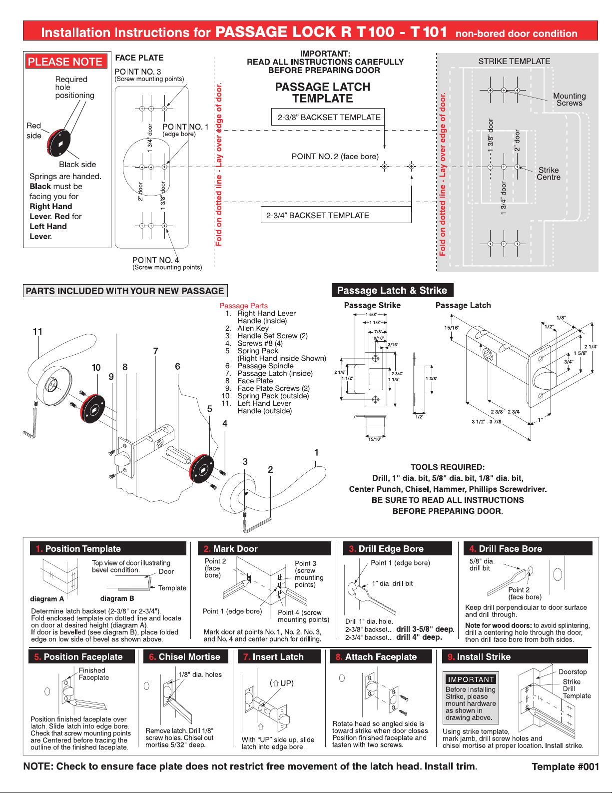
TOOLS REQUIRED:
Drill, 1" dia. bit, 5/8" dia. bit, 1/8" dia. bit, Center Punch, Chisel, Hammer, Phillips Screwdriver.
BE SURE TO READ ALL INSTRUCTIONS BEFORE PREPARING DOOR.
2-3/4” BACKSET TEMPLATE
2-3/8” BACKSET TEMPLATE
POINT NO. 2 (face bore)
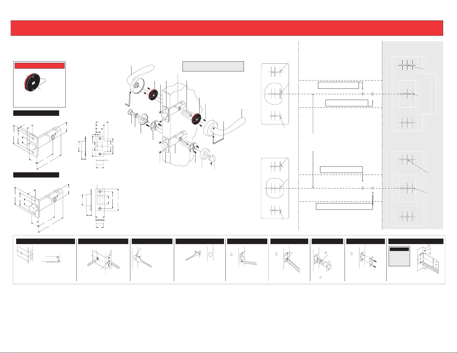
PRIVACY MORTISE
BOLT TEMPLATE
2-3/4” BACKSET TEMPLATE
2-3/8” BACKSET TEMPLATE
STRIKE TEMPLATE
STRIKE TEMPLATE
Mounting
Screws
Strike
Centre
door
PASSAGE LATCH TEMPLATE
IMPORTANT:
READ ALL INSTRUCTIONS CAREFULLY
BEFORE PREPARING DOOR
Fold on dotted line - Lay over edge of door.
Fold on dotted line - Lay over edge of door.
Mounting
Screws
Strike
Centre
POINT NO. 2 (face bore)
POINT NO. 3
(Screw mounting points)
1 3/8” door
1 3/4” door
FACE PLATE
POINT NO. 1
(edge bore)
POINT NO. 4
(Screw mounting points)
POINT NO. 3
(Screw mounting points)
1 3/4” door
1 3/8” door
POINT NO. 1
(edge bore)
POINT NO. 4
(Screw mounting points)
FACE PLATE
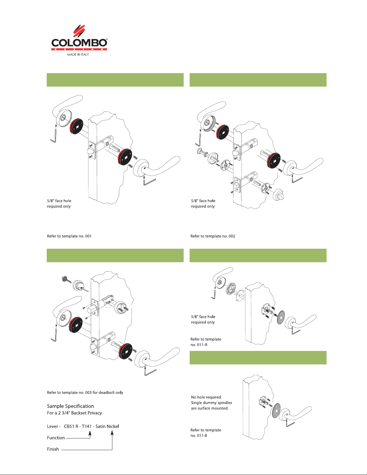
Installation Instructions for PRIVACY LOCK R - T140 - T141 - non-bored door condition
PARTS INCLUDED WITH YOUR
NEW PRIVACY LOCK
Passage Parts
1. Right Hand Lever Handle (inside)
2. Allen Key
3. Handle Set Screw (2)
4. Screws #8 (4)
5. Spring Pack (Right Hand inside Shown)
6. Passage Spindle
7. Passage Latch (inside)
8. Face Plate
9. Face Plate Screws (2)
10. Spring Pack (outside)
11. Left Hand Lever Handle (outside)
1
2
4
5
6
7
11
1
3
6
8
9
4
5
8
3
10
11
Privacy Parts
1. Thumbturn (inside)
2. Thumbturn Set Screw
3. Rose (inside)
4. Screws #4 (4)
5. Springless Pack (inside)
6. Privacy Bolt
7. Face Plate
8. Face Plate Screws (2)
9. Springless Pack (outside)
10. Rose
11. Washer
12. Emergency Release Spindle
2” door 2” door
2
3-1/2”
12
2” door
2” door
9
10
7
Recommended
Center
to Center
1 3/8”
1 5/8”
1 1/8”
7/8”
9/16”
3/16”
2 3/4”
1 1/8” 1 1/2”
2 1/8”
15/16”
1/2”
15/16”
1/8”
1/2”
3/4”
1 5/8”
2 1/4”
1”
2 3/8 - 2 3/4”
3 1/2” - 3 7/8”
2 1/4”
1 5/8”
3/4”
1/2”
1”
15/16”
2 3/8 - 2 3/4”
3 1/2” - 3 7/8”
Passage Latch & Strike
Privacy Bolt & Strike
Privacy Bolt
Passage Latch Passage Strike
NOTE: Check to ensure face plate does not restrict free movement of the latch head. Install trim. Repeat instruction 1 - 9 for privacy bolt.
1. Position Template
diagram A
Determine latch backset (2-3/8" or 2-3/4").
Fold enclosed template on dotted line and locate
on door at desired height (diagram A).
If door is bevelled (see diagram B), place folded
edge on low side of bevel as shown above.
Top view of door illustrating
bevel condition.
diagram B
Door
Template
2. Mark Door
Mark door at points No. 1, No. 2, No. 3,
and No. 4 andcenter punch for drilling.
Point 2
(face bore)
Point 3
(screw mounting points)
Point 1 (edge bore) Point 4 (screw
mounting points)
3. Drill Edge Bore
1” dia. drill bit
Point 1 (edge bore)
Drill 1" dia. hole.
2-3/8" backset....
drill 3-5/8" deep
.
2-3/4" backset....
drill 4" deep.
4. Drill Face Bore
Point 2
(face bore)
5/8" dia. drill bit
Keep drill perpendicular to door surface
and drill through.
Note for wood doors: to avoid splintering,
drill a centering hole through the door,
then drill face bore from both sides.
5. Position Faceplate
Position finished faceplate over
latch. Slide latch into edge bore.
Check that screw mounting points
are Centered before tracing the
outline of the finished faceplate.
Finished
Faceplate
6. Chisel Mortise
Remove latch. Drill 1/8" screw
holes. Chisel out mortise 5/32"
deep.
1/8" dia. holes
7. Insert Latch
With “ U P " side up, slide
latch into edge bore.
UP)
(
8. Attach Faceplate
Rotate latch so angled side is
toward strike when door closes.
Position finished faceplate and
fasten with two screws.
9. Install Strike
Using strike template,
mark jamb, drill screw holes and chisel mortise
at proper location. Install strike.
Strike
Drill
Template
Doorstop
IMPORTANT
Before Installing
Strike, please
mount hardware
as shown in
drawing above.
PLEASE NOTE
Black side
Red side
Springs are handed. Blackmust be
facing you for Right Hand Lever.
Red for Left Hand Lever.
Required
hole
positioning
1 3/8”
1/2”
1 1/8”
11/16”
1 1/16”
2 1/8”
2 3/4”
7/8”
Privacy Strike
1 3/8” door
1 3/4” door
1 3/8” door
1 3/4”
Template #002-RH