Columbus McKinnon DORNER 2200 Series User manual

851-873-EU Rev. B
For other service manuals visit our website at:
www.dornerconveyors.com/manuals-literature
Record Conveyor Serial Number Here
Original Instructions
2200 Series Modular Belt
Conveyors
Installation, Maintenance & Parts Manual

Dorner Mfg. Corp. 2 851-873-EU Rev. B
2200 Series Modular Belt Conveyors
Table of Contents
Introduction ......................................................................... 3
Warnings −General Safety ................................................. 4
Product Description ............................................................. 5
Specifications ...................................................................... 6
Models: ............................................................................ 6
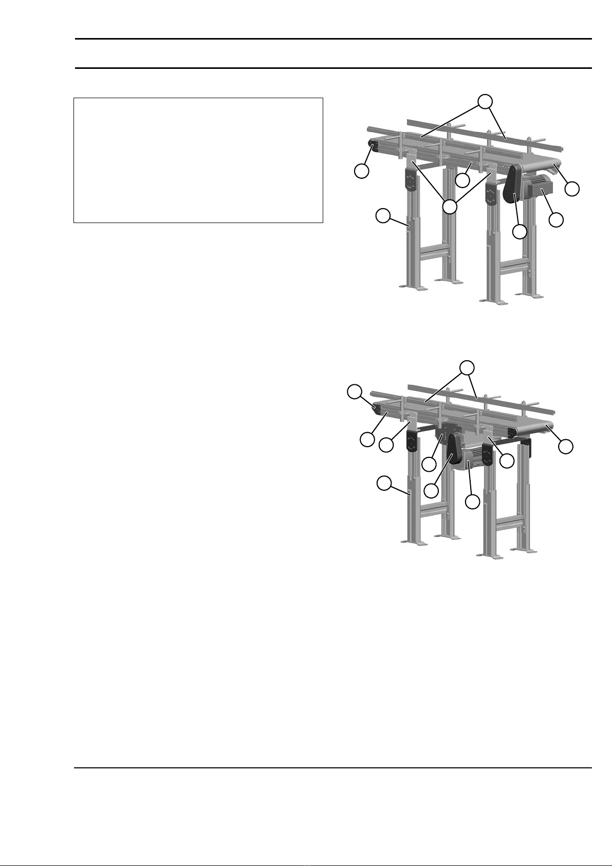
Flat Belt End Drive Conveyor...................................... 6
Cleated Belt End Drive Conveyor................................ 6
Flat Belt Center Drive Conveyor ................................. 6
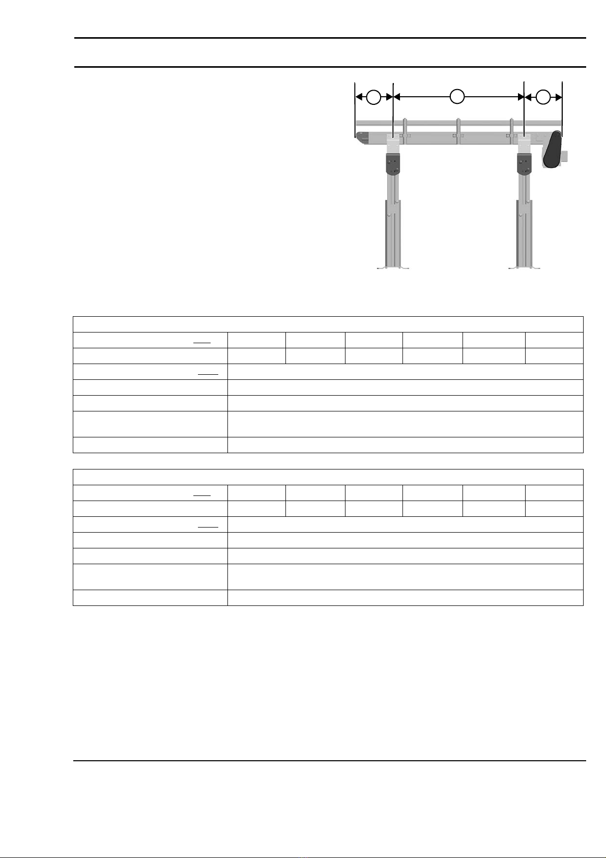
Conveyor Supports: ......................................................... 7
Maximum Distances:.................................................... 7
Conveyor Specifications:................................................. 7
Installation ........................................................................... 8
Required Tools................................................................. 8
Recommended Installation Sequence .............................. 8
Conveyors Up to 3048 mm .............................................. 8
Conveyors Longer Than 3658 mm .................................. 9
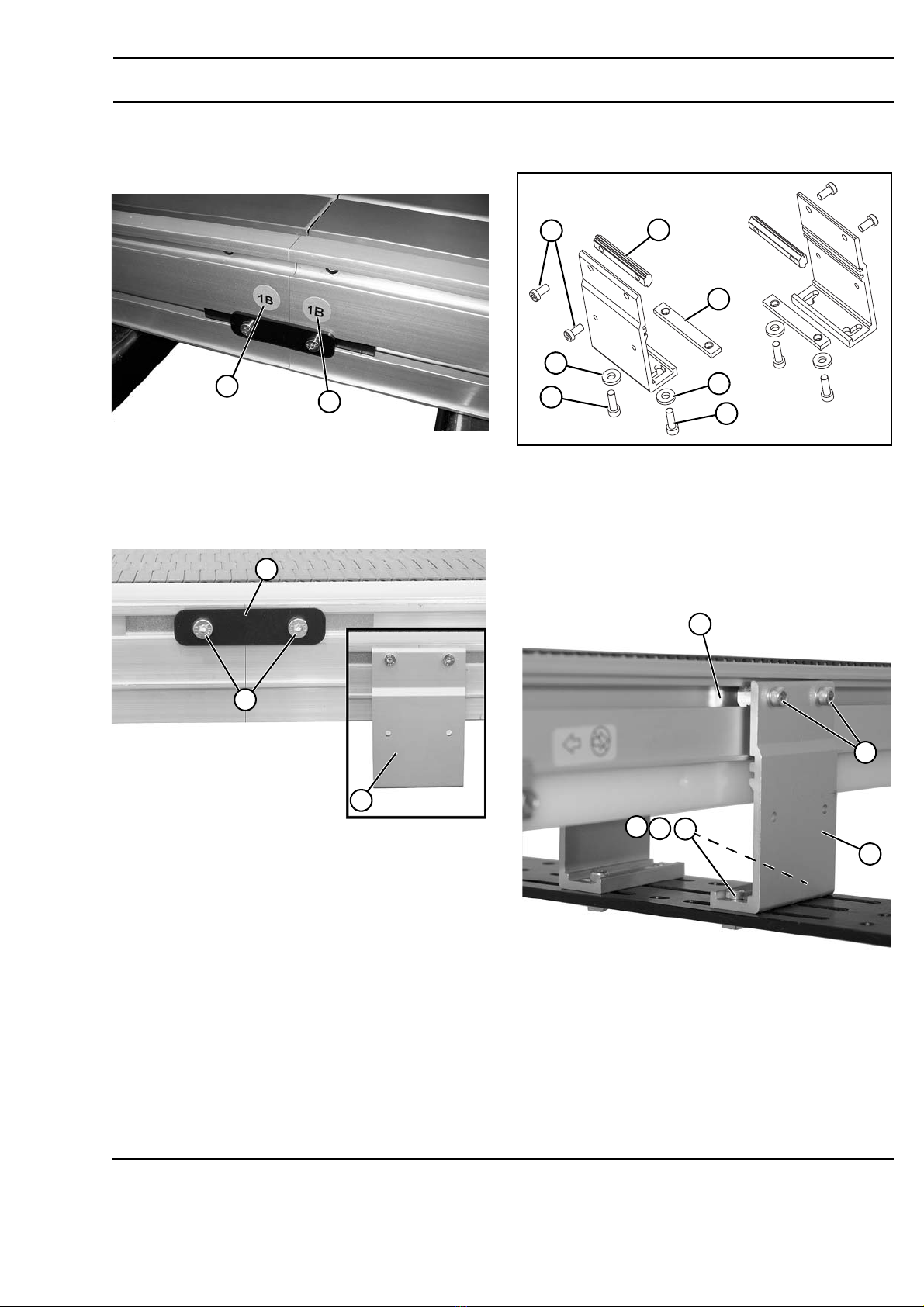
Mounting Brackets........................................................... 9
Installing Plastic Belt ..................................................... 10
Guide Clips .................................................................... 11
Adjustable Guides.......................................................... 11
Preventive Maintenance and Adjustment.......................... 13
Required Tools............................................................... 13
Standard Tools............................................................ 13
Special Tools .............................................................. 13
Checklist ........................................................................ 13
Lubrication..................................................................... 13
Maintaining Conveyor Belt ........................................... 13
Troubleshooting ......................................................... 13
Cleaning ..................................................................... 13
Conveyor Belt Replacement .......................................... 13
Conveyor Belt Replacement Sequence ...................... 13
Belt Removal.............................................................. 14
Belt Installation .......................................................... 15
Conveyor Belt Tension .................................................. 15
Removal of Belt Links ............................................... 16
Micropitch Belts ..................................................... 16
Metalworking Belts ................................................ 17
Pulley Removal.............................................................. 18
A −End Drive Conveyor ........................................... 18
B −Center Drive Conveyor ....................................... 19
Bearing and Sprocket Removal and Replacement......... 21
Removal ..................................................................... 21
Replacement ............................................................... 21
Idler End Wear Items..................................................... 22
A - Standard Idler Tail ............................................... 22
B - Nose Bar Idler Tail............................................... 23
Frame Wear Strip Replacement..................................... 23
Center Rail Replacement ............................................... 24
Tail Plate Shaft Knockout Removal .............................. 25
Service Parts ...................................................................... 26
End Drive Tail ............................................................... 26
Idler Tail for Conveyors up to 6096 mm Long.............. 28
Idler Tail for Conveyors Over 6096 mm Long.............. 29
Nose Bar Idler Tail ........................................................ 30
Center Drive Module ..................................................... 31
Frame Assembly ............................................................ 32
#04 Profile - 76 mm Aluminum Side ............................. 33
#05 Profile - 38 mm Aluminum Side ............................. 34
#13, 33 & 43 Profile - Adjustable Guiding .................... 35
#14, 34 & 44 Profile - Tool-Less Adjustable Guiding ... 36
25 mm Cleated Profiles .................................................. 37
51 mm Cleated Profiles .................................................. 38
Flat Belt Mounting Brackets .......................................... 39
Cleated Belt Mounting Brackets .................................... 39
Flat Belt Mounting Brackets for Short Conveyors......... 40
Cleated Belt Mounting Brackets for Short Conveyors... 40
Flat Belt Connecting Assembly with Stand Mount........ 41
Cleated Belt Connecting Assembly with Stand Mount.. 41
Connecting Assembly without Stand Mount.................. 42
Micropitch Conveyor Belting......................................... 43
Metalworking Conveyor Belting.................................... 43
Return Policy...................................................................... 44

851-873-EU Rev. B 3 Dorner Mfg. Corp.
2200 Series Modular Belt Conveyors
Introduction
Upon receipt of shipment:
• Compare shipment with packing slip. Contact factory
regarding discrepancies.
• Inspect packages for shipping damage. Contact carrier
regarding damage.
• Accessories may be shipped loose. See accessory instruc-
tions for installation.
Dorner’s Limited Warranty applies.
Dorner 2200 series conveyors are covered by Patent
Numbers 5,174,435, 6,298,981, 6,422,382 and
corresponding patents and patent applications in other
countries.
Dorner reserves the right to make changes at any time
without notice or obligation.
Dorner has convenient, pre−configured kits of Key Service
Parts for all conveyor products. These time saving kits are
easy to order, designed for fast installation, and guarantee
you will have what you need when you need it. Key Parts
and Kits are marked in the Service Parts section of this
manual with the Performance Parts Kits logo .
IMPORTANT
Some illustrations may show guards
removed. DO NOT operate equipment
without guards.

Dorner Mfg. Corp. 4 851-873-EU Rev. B
2200 Series Modular Belt Conveyors
Warnings −General Safety
A
WARNING
The safety alert symbol, black triangle with
white exclamation, is used to alert you to
potential personal injury hazards.
A
DANGER
Climbing, sitting, walking or riding on
conveyor will cause severe injury. KEEP OFF
CONVEYORS.
A
DANGER
DO NOT OPERATE CONVEYORS IN AN
EXPLOSIVE ENVIRONMENT.
A
WARNING
Gearmotors may be HOT.
DO NOT TOUCH Gearmotors.
A
WARNING
Exposed moving parts can cause severe
injury. LOCK OUT POWER before removing
guards or performing maintenance.
A
WARNING
Conveyors are not reversible. Reversing
creates pinch points which can cause severe
injury.
DO NOT REVERSE CONVEYORS.
A
WARNING
Top and Bottom Mount Gearmotors must be
mounted as shown below.
Failure to do so creates pinch points which
can cause severe injury.
A
WARNING
Dorner cannot control the physical
installation and application of conveyors.
Taking protective measures is the
responsibility of the user.
When conveyors are used in conjunction
with other equipment or as part of a multiple
conveyor system, CHECK FOR POTENTIAL
PINCH POINTS and other mechanical
hazards before system start-up.
A
WARNING
Loosening stand height or angle adjustment
screws may cause conveyor sections to drop
down, causing severe injury.
SUPPORT CONVEYOR SECTIONS PRIOR TO
LOOSENING STAND HEIGHT OR ANGLE
ADJUSTMENT SCREWS.
Bottom Mount
Top Mount

851-873-EU Rev. B 5 Dorner Mfg. Corp.
2200 Series Modular Belt Conveyors
Product Description
Refer to Figure 1 for typical conveyor components. Figure 1
End Drive Conveyor
Figure 1
Figure 2
Center Drive Conveyor
Figure 2
1Conveyor
2 Guiding
3 Mounting Brackets
4 Support Stand
5DriveEnd
6 Idler/Tension End
7 Gearmotor Mounting Package
8 Gearmotor
9 Center Drive Box (Center Drive Units) 43
1
6
2
5
8
7
4
3
1
6
3
5
2
9
8
7

Dorner Mfg. Corp. 6 851-873-EU Rev. B
2200 Series Modular Belt Conveyors
Specifications
Models:
Flat Belt End Drive Conveyor
Cleated Belt End Drive Conveyor
Flat Belt Center Drive Conveyor
* See Engineering Manual for details.
Center drive location to be at center of first frame section.
Minimum center drive conveyor length is 91 cm.
Conveyor Length
Mounting Bracket Options
Idler Tail Type
Shaft Position
Conveyor Width
22MTE M WW LLLL B PA BB
Document Language
Profile (A side)
PD -
I D
Profile (D side)
Belt Type
-X1234
Tail 4 Auxiliary
Tail 3 Auxiliary
Shaft Option
Tail 2 Auxiliary
Shaft Option
Tail 1 Auxiliary
Shaft Option
Auxiliary Shaft Exists
Shaft Option
Conveyor Length
Mounting Bracket Options
Shaft Position
Cleat Height
Conveyor Width
22MTC M WW LLLL B BB
Document Language
Profiles
SSSS-
DC
Cleat Spacing
Belt Type
-X1234
Tail 4 Auxiliary
Shaft Option
Tail 3 Auxiliary
Shaft Option
Tail 2 Auxiliary
Shaft Option
Tail 1 Auxiliary
Shaft Option
Auxiliary Shaft Exists
P
Conveyor Length
Mounting Bracket Options
Infeed Tail Type
Shaft Position
Conveyor Width
22MTD M WW LLLL B PA BB
Document Language
Profile (A side)
PD -
I D
Profile (D side)
Belt Type
-X1234
Tail 4
Auxiliary
Shaft Option
Tail 3
Auxiliary
Shaft Option
Tail 2
Auxiliary
Shaft Option
Tail 1
Auxiliary
Shaft Option
Auxiliary Shaft
Exists
E
Discharge Tail Type
-LL
Drive Distance from
Exit Tail

851-873-EU Rev. B 7 Dorner Mfg. Corp.
2200 Series Modular Belt Conveyors
Specifications
Conveyor Supports:
Maximum Distances:
1 = 457 mm**
2 = 1829 mm***
3 = 457 mm
** For Heavy Load Bottom Mount Package, mount support
under gear head.
*** For conveyors longer than 3048 mm, install support at
joint.
Figure 3
Figure 3
Conveyor Specifications:
* See Engineering Manual for details.
13
2
Standard Micropitch Belts
Conveyor Width Reference (WW)04 06 08 12 18 24
Conveyor Belt Width 102 mm 152 mm 203 mm 305 mm 457 mm 610 mm
Conveyor Length Reference (LLLL) 01500 to 3000 in 001 increments
Conveyor Length 457 mm to 9144 mm in 3 mm increments
Belt Travel 136 mm per revolution of pulley
End / Center Drive Maximum Belt
Speed*
76.2 m/minute
iDrive Maximum Belt Speed* 27.4 m/minute
Standard Metalworking Belts
Conveyor Width Reference (WW)03 06 09 12 18 24
Conveyor Belt Width 76 mm 152 mm 229 mm 305 mm 457 mm 610 mm
Conveyor Length Reference (LLLL) 01500 to 3000 in 001 increments
Conveyor Length 457 mm to 9144 mm in 3 mm increments
Belt Travel 150 mm per revolution of pulley
End / Center Drive Maximum Belt
Speed*
76.2 m/minute
iDrive Maximum Belt Speed* 27.4 m/minute

Dorner Mfg. Corp. 8 851-873-EU Rev. B
2200 Series Modular Belt Conveyors
Installation
Figure 4
Figure 4
Required Tools
• Hex-key wrenches: 4 mm, 5 mm
• Level
• Torque wrench
• 2.4 mm wide flat blade screwdriver
Recommended Installation
Sequence
• Install support stands (see accessory instructions)
• Assemble conveyor frame (if required)
• Attach mounting brackets to conveyor frame and stands
• Install belt
• Mount gearmotor mounting package (see accessory
instructions)
• Attach guides/accessories. (See “Service Parts” section
beginning on page 26 for details.)
Conveyors Up to 3048 mm
No assembly is required. Install mounting brackets. Refer to
“Mounting Brackets” on page 9.
A
WARNING
Conveyors are not reversible. Reversing
creates pinch points which can cause severe
injury.
DO NOT REVERSE CONVEYORS.
A
WARNING
Top and Bottom Mount Gearmotors must be
mounted as shown below.
Failure to do so creates pinch points which
can cause severe injury.
NOTE
Conveyor MUST be mounted straight, flat and
level within confines of conveyor. Use a level
(Figure 4, item 1) for setup.
Bottom Mount
Top Mount
1

851-873-EU Rev. B 9 Dorner Mfg. Corp.
2200 Series Modular Belt Conveyors
Installation
Conveyors Longer Than 3658 mm
1. Locate and arrange conveyor sections by section labels
(Figure 5, item 1).
Figure 5
Figure 5
2. Join conveyor sections and install connector brackets
(Figure 6, item 1) or connector/mount brackets (Figure
6, item 2) and screws (Figure 6, item 3) on both sides
as indicated.
Figure 6
Figure 6
3. Tighten screw (Figure 6, item 3) to 7 Nm on both sides
of conveyor.
Mounting Brackets
1. Locate brackets. Exploded view shown in Figure 7.
Figure 7
Figure 7
2. Remove screws (Figure 7, item 1 & 2), washers
(Figure 7, item 3), connector bars (Figure 7, item 4)
and T-bars (Figure 7, item 5) from brackets.
3. Insert T-bars (Figure 7, item 5) into conveyor side slots
(Figure 8, item 1). Fasten brackets (Figure 8, item 2)
to conveyor with mounting screws (Figure 8, item 3).
Figure 8
Figure 8
4. Fasten brackets to support stand with mounting screws
(Figure 8, item 4), washers (Figure 8, item 5) and nuts
(Figure 8, item 6).
5. Tighten screws (Figure 8, item 3 & 4) to 7 Nm.
1
1
1
3
2
15
4
3
23
2
6
1
3
2
45

Dorner Mfg. Corp. 10 851-873-EU Rev. B
2200 Series Modular Belt Conveyors
Installation
Installing Plastic Belt
1. Locate the conveyor belt retaining rod (Figure
9, item 1).
Figure 9
Figure 9
2. Align the belt grooves (Figure 10, item 1) or (Figure
11, item 1) to the evenly spaced sprockets (Figure
10, item 2) or (Figure 11, item 2) on the drive end of
the conveyor.
Figure 10
Micropitch Belt
Figure 10
Figure 11
Metalworking Belt
Figure 11
3. Feed belt into bottom wear strips (Figure 12, item 1)
and pull through to the far end.
Figure 12
Figure 12
4. Splice the belt together by pushing the plastic rod
(Figure 13, item 1) through the side hole on the rod
retaining side of belt.
Figure 13
Figure 13
1
1
1
2
2
11
1
1

851-873-EU Rev. B 11 Dorner Mfg. Corp.
2200 Series Modular Belt Conveyors
Installation
Guide Clips
1. Install guide clip assembly (Figure 14, item 1) into
conveyor t-slot (Figure 14, item 2) as shown.
Figure 14
Figure 14
2. Tighten screw (Figure 15, item 1) making sure t-bar
(Figure 15, item 2) rotates and engages inside of t-slot.
Figure 15
Figure 15
Adjustable Guides
1. Install guide bracket assembly (Figure 16, item 1) into
the conveyor t-slot (Figure 16, item 2).
Figure 16
Figure 16
2. Tighten screws (Figure 17, item 1) making sure t-nut
(Figure 17, item 2) rotates and engages inside of the t-
slot.
Figure 17
Figure 17
3. Loosen screw (Figure 18, item 1) on end of shaft
(Figure 18, item 2) to remove clip (Figure 19, item 1).
Figure 18
Figure 18
Figure 19
Figure 19
1
2
1
2
1
2
1
2
1
2
1

Dorner Mfg. Corp. 12 851-873-EU Rev. B
2200 Series Modular Belt Conveyors
Installation
4. Snap clip (Figure 20, item 1) onto guide rail (Figure
20, item 2).
Figure 20
Figure 20
5. Reassemble clip (Figure 21, item 1) and attach to shaft
(Figure 21, item 2). Tighten screw (Figure 18, item 1)
on end of shaft.
Figure 21
Figure 21
6. Adjust rail width with top screw (Figure 22, item 1).
Figure 22
Figure 22
7. Adjust rail height with lower screw (Figure 23, item 1).
Figure 23
Figure 23
1
2
1
2
1
1

851-873-EU Rev. B 13 Dorner Mfg. Corp.
2200 Series Modular Belt Conveyors
Preventive Maintenance and Adjustment
Required Tools
Standard Tools
• Hex-key wrenches: 2.5 mm, 4 mm, 5 mm
• 2.4 mm wide flat blade screw driver
• Arbor press
• Adjustable wrench to 25 mm wide
Special Tools
• 807−1078 Sealed Bearing Removal Tool
• 450293 Sealed Bearing Installation Tool
Checklist
• Keep service parts on hand (see “Service Parts” section for
recommendations)
• Keep supply of belt cleaner
• Clean entire conveyor while disassembled
• Replace worn or damaged parts
Lubrication
No lubrication is required. Replace bearings if worn.
Maintaining Conveyor Belt
Troubleshooting
Inspect conveyor belt for:
• Surface cuts or wear
• Tooth skipping
• Loose links
Surface cuts and wear indicate:
• Sharp or heavy parts impacting belt
• Jammed parts
• Foreign material inside the conveyor
• Improperly positioned accessories
• Bolt-on guiding is pinching belt
Stalling or skipping belt indicates:
• Belt stretching
• Conveyor belt or drive timing belt are not properly ten-
sioned
• Worn sprocket or impacted dirt on drive pulley
• Intermittent jamming or drive train problems
Cleaning
Use mild soap and water to clean the belt and conveyor. Do
not soak the belt.
Conveyor Belt Replacement
Conveyor Belt Replacement Sequence
• Remove old conveyor belt
• Install new conveyor belt
IMPORTANT
Do not use belt cleaners that contain alcohol,
acetone, Methyl Ethyl Ketone (MEK) or other
harsh chemicals.
A
WARNING
Exposed moving parts can cause severe
injury. LOCK OUT POWER before removing
guards or performing maintenance.

Dorner Mfg. Corp. 14 851-873-EU Rev. B
2200 Series Modular Belt Conveyors
Preventive Maintenance and Adjustment
Belt Removal
1. Choose one link on either end of the conveyor to
remove belt pin. Locate end of rod without retaining
feature (Figure 24, item 1).
Figure 24
Micropitch Belt
Figure 24
2. Insert punch (Figure 25, item 1) into non-retaining side
of belt, pushing rod out.
Figure 25
Micropitch Belt
Figure 25
3. Remove rod (Figure 26, item 1) and separate belt.
Figure 26
Micropitch Belt
Figure 26
4. Choose one link on the idler end of chain to remove
endcaps. With a 2.4 mm flat blade screwdriver, pry
under tab of end caps (Figure 27, item 1) and remove
end cap. Repeat for opposite side of conveyor.
Figure 27
Metalworking Belt
Figure 27
5. Insert screwdriver (Figure 28, item 1) into one side of
belt, pushing rod (Figure 28, item 2) out. Remove rod
and separate belt.
Figure 28
Metalworking Belt
Figure 28
IMPORTANT
You may need to slightly raise the underside
of the conveyor belt to properly drive pin out
of slots.
NOTE
For Micropitch Belts follow steps 1, 2, 3, 6 and
7. For Metalworking Belts follow steps 4, 5, 6
and 7.
1
1
1
1
1
2

851-873-EU Rev. B 15 Dorner Mfg. Corp.
2200 Series Modular Belt Conveyors
Preventive Maintenance and Adjustment
6. Pull back topside of belt to the drive end of the
conveyor. See Figure 29.
Figure 29
Figure 29
7. Remove belt by pulling belt out of bottom wear strips
(Figure 30, item 1).
Figure 30
Figure 30
Belt Installation
1. See “Installing Plastic Belt” page 10.
Conveyor Belt Tension
Figure 31
Figure 31
Figure 32
Figure 32
1
1
A
WARNING
Exposed moving parts can cause severe
injury. LOCK OUT POWER before removing
guards or performing maintenance.
NOTE
The Modular Belt Conveyor is designed to
operate with minimal belt tension. Conveyor
will come with proper amount of belt sag at
drive end of conveyor belt. See Figure 31. As
belt stretches, it may be necessary to remove
links to avoid too much belt sag. See Figure
32.

Dorner Mfg. Corp. 16 851-873-EU Rev. B
2200 Series Modular Belt Conveyors
Preventive Maintenance and Adjustment
Removal of Belt Links
Micropitch Belts
1. Choose one link on either end of the conveyor to
remove belt pin. Locate end of rod without retaining
feature (Figure 33, item 1).
Figure 33
Figure 33
2. Insert punch (Figure 34, item 1) into non-retaining side
of belt, pushing rod out.
Figure 34
Figure 34
3. Remove rod (Figure 35, item 1) and separate belt.
Figure 35
Figure 35
4. Determine the number of links to be removed. Start with
1 link and remove more as needed. If additional
tensioning is required repeat steps 1 - 3.
A
WARNING
Operating conveyor with belt sag beyond
maximum shown in Figure 32 will create belt
pinch points which can cause injury.
REMOVE BELT LINKS IF MAXIMUM SAG IS
REACHED
IMPORTANT
You may need to slightly raise the underside
of the conveyor belt to properly drive pin out
of slots.
1
1
1

851-873-EU Rev. B 17 Dorner Mfg. Corp.
2200 Series Modular Belt Conveyors
Preventive Maintenance and Adjustment
5. Splice the belt together by pushing the plastic rod
(Figure 36, item 1) through the side hole on the rod
retaining side of belt.
Figure 36
Figure 36
6. Review belt sag at drive end to ensure it stays within the
sag area of the tail. If additional tensioning is required
repeat steps 1 - 5.
Metalworking Belts
1. Choose one link on the idler end of chain to remove
endcaps. With a 2.4 mm flat blade screwdriver, pry
under tab of end caps (Figure 37, item 1) and remove
end cap. Repeat for opposite side of conveyor.
Figure 37
Figure 37
2. Insert screwdriver (Figure 38, item 1) into one side of
belt, pushing rod (Figure 38, item 2) out. Remove rod
and separate belt.
Figure 38
Figure 38
3. Determine the number of links to be removed. Start with
1 link and remove more as needed. If additional
tensioning is required repeat steps 1 and 2.
4. Splice the belt together by pushing the plastic rod
(Figure 39, item 1) through the side hole.
Figure 39
Figure 39
5. Insert rod retaining end caps (Figure 40, item 1) on
both sides of belt.
Figure 40
Figure 40
6. Review belt sag at drive end to ensure it stays within the
sag area of the tail. If additional tensioning is required
repeat steps 1 - 5.
1
1
1
2
1
1

Dorner Mfg. Corp. 18 851-873-EU Rev. B
2200 Series Modular Belt Conveyors
Preventive Maintenance and Adjustment
Pulley Removal
Remove conveyor belt to access pulley(s). See “Conveyor
Belt Replacement” on page 13. Remove the desired pulley
following the corresponding instructions below:
•A−End Drive Conveyor
•B−Center Drive Conveyor
A −End Drive Conveyor
1. Remove belt from drive tail. See “Belt Removal” on
page 14.
2. Remove upper wear strips (Figure 41, item 1) from end
drive.
Figure 41
Figure 41
3. Remove lower wear strips (Figure 42, item 1) from end
drive.
Figure 42
Figure 42
4. Loosen two fastening screws (Figure 43, item 1) on
both sides of conveyor.
Figure 43
Figure 43
5. Remove end drive (Figure 44, item 1) from conveyor.
Figure 44
Figure 44
A
WARNING
Exposed moving parts can cause severe
injury. LOCK OUT POWER before removing
guards or performing maintenance.
A
WARNING
Drive shaft keyway may be sharp. HANDLE
WITH CARE.
1
1
1
1

851-873-EU Rev. B 19 Dorner Mfg. Corp.
2200 Series Modular Belt Conveyors
Preventive Maintenance and Adjustment
6. Remove headplate (Figure 45, item 1) and spindle
(Figure 45, item 2).
Figure 45
Figure 45
7. Remove and replace worn bearings and sprockets. See
“Bearing and Sprocket Removal and Replacement” on
page 21.
8. Reassemble in reverse order.
B −Center Drive Conveyor
1. Loosen screw (Figure 46, item 1) on each side of
conveyor.
Figure 46
Figure 46
2. Lower bracket (Figure 47, item 1).
Figure 47
Figure 47
3. Remove screw (Figure 48, item 1) on both sides of
bracket and remove takeup roller (Figure 48, item 2).
Figure 48
Figure 48
4. Remove belt from drive tail. See “Belt Removal” on
page 14.
5. Loosen screw (Figure 49, item 1) on both sides of the
conveyor to remove center drive module (Figure
49, item 2).
Figure 49
Figure 49
1
2
1
1
1
2
1
2

Dorner Mfg. Corp. 20 851-873-EU Rev. B
2200 Series Modular Belt Conveyors
Preventive Maintenance and Adjustment
6. Remove two screws (Figure 50, item 1) on both sides
of the center drive module.
Figure 50
Figure 50
7. Remove four screws (Figure 50, item 2) from the non-
motor side of the center drive module.
8. Remove side plate (Figure 51, item 1).
Figure 51
Figure 51
9. Remove drive shaft (Figure 52, item 1).
Figure 52
Figure 52
10. Remove and replace worn bearings and sprockets. See
“Bearing and Sprocket Removal and Replacement” on
page 21.
11. Remove shafts (Figure 53, item 1), replace if worn.
Figure 53
Figure 53
12. Reassemble in reverse order.
Figure 54
Figure 54
2
2
1
1
1
NOTE
Please take note of the idler assembly
locations. The center idler assembly uses the
lower hole (Figure 54, item 1) for Micropitch
conveyor belts (Types 01-02) and the upper
holes (Figure 54, item 2) for Metalworking
conveyor belts (Types 30-42).
1
1
2
Table of contents
Other Columbus McKinnon Industrial Equipment manuals

Columbus McKinnon
Columbus McKinnon Yale HTP 1000 ATEX Operating instructions

Columbus McKinnon
Columbus McKinnon TIGRIP THM Operating instructions

Columbus McKinnon
Columbus McKinnon MAGNETEK LaserGuard Mini User manual

Columbus McKinnon
Columbus McKinnon TIGRIP TBL User manual

Columbus McKinnon
Columbus McKinnon TIGRIP TPZ 0,4/55 User manual