9/53
In case of needing to drive the device by a different gas, this transformation must be carried out a certified specialist or an authorized
service.
When determining any gas leakage, gas valve must be closed and burning must be ended up.
This appliance is only for professional use and that it shall be used by qualified people
If the fire stops continuously, authorized service must be called.
It is necessary to call an authorized service for installing the device, and if necessary, for changing in order to use it with other gases.
The information about gas installation has been given in instruction manual.
Gas adjustments can only be changed by your authorized service. Do not be involved in the adjustments.
Qualified installer should be called in to install the appliance and, if necessary, to convert it for use with other gases, in keeping with
currently installation regulations in country in whıch the apliance is to be installled.
4. COMING THINGS TOGETHER WITH THE PRODUCT
A. Description Catalogue
B. User/Maintenance/Assembling Manual
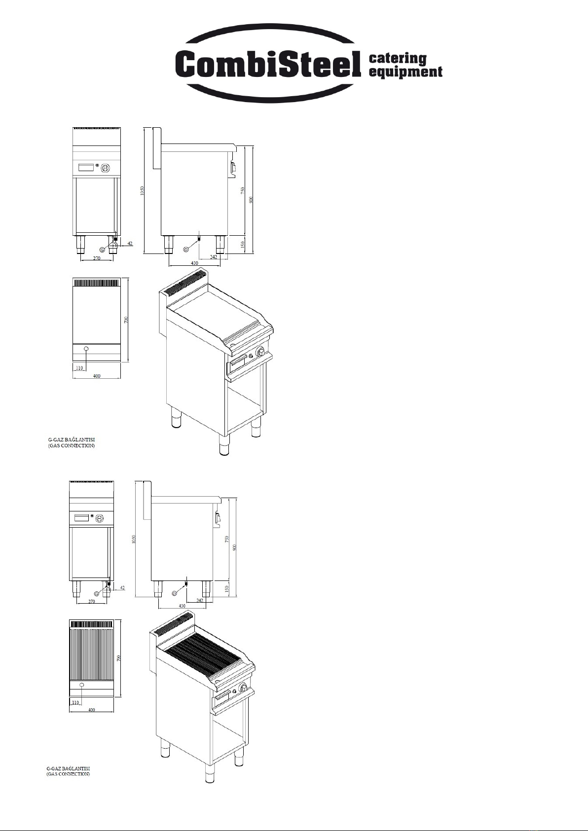
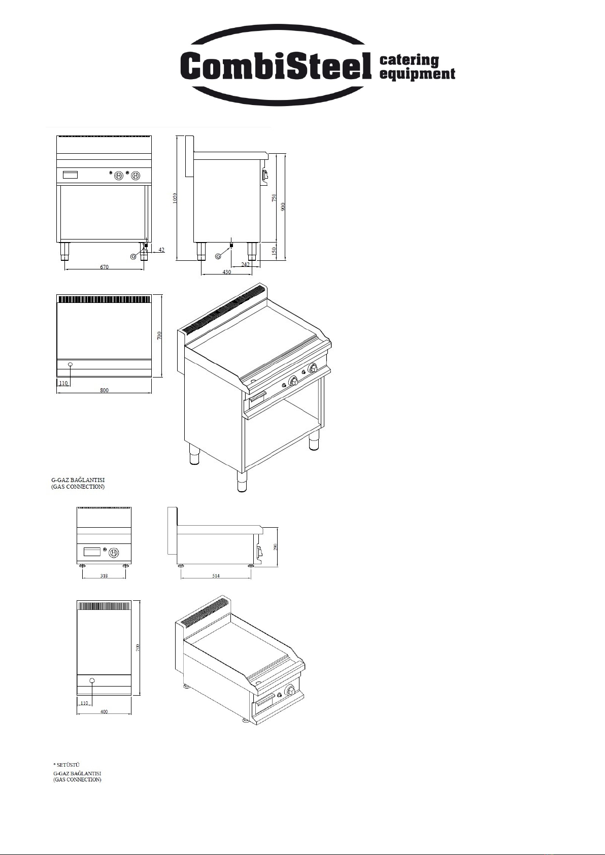
5. DEVICE DESCRIPTION/EXPLANATION
The device have wholly manufactured regarding to hygienic standards.
The legs are in adjustable feature and manufactured by stainless steel material.
For the insulation purposes, glass- wool and stone–wool have been used. Thanks to this application, wasting of energy can be able to
prevent.
It can work by LPG or natural gas.
Burner has safety valve and thermocouple. If the fire puts off, gas flow stops.
6. PLACING THE DEVICE AND PREPARING IT FOR START UP
While the devices are in operation, do not keep burning material (plastic bags, table napkin, clothe etc.) near them.
Read the instruction and maintenance manual absolutely.
Open the packing of the device and remove all protective tapes.
Opening the cover of the device, take out the instruction manual and guarantee document.
Place on the ground the machine with adjustable leg in type by adjusting its legs, for fixed the devices with fixed leg, by smoothing the
ground.
There must be sufficient ventilation in the area, where you operate the device.
Place your device 10 cm away from the surfaces not heat resistant and the wall.
7. PRE-INSPECTIONS TO BE PERFORMED FOR START UP
Be sure that appropriate gas is used.
Be sure that there isn’t any leakage on the gas connection of the device.
Read the instruction manual absolutely
8. START UP
On the figures in gas control section, the figures of control panels existing on the device have been shown. According to these figures,
check whether or not gas connection have been made exactly and correctly, as mentioned earlier.
Because Control switches existing on the device are graded, we can provide any cooking in power we desire. (FIGURE 2)