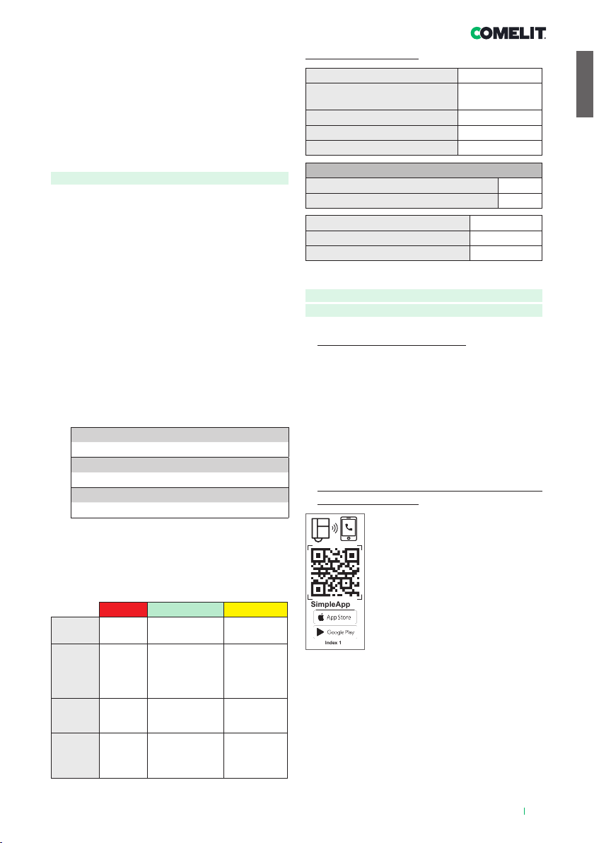
Fig. 1
1.
2.
3.
4.
6.
7.
8.
9.
5.
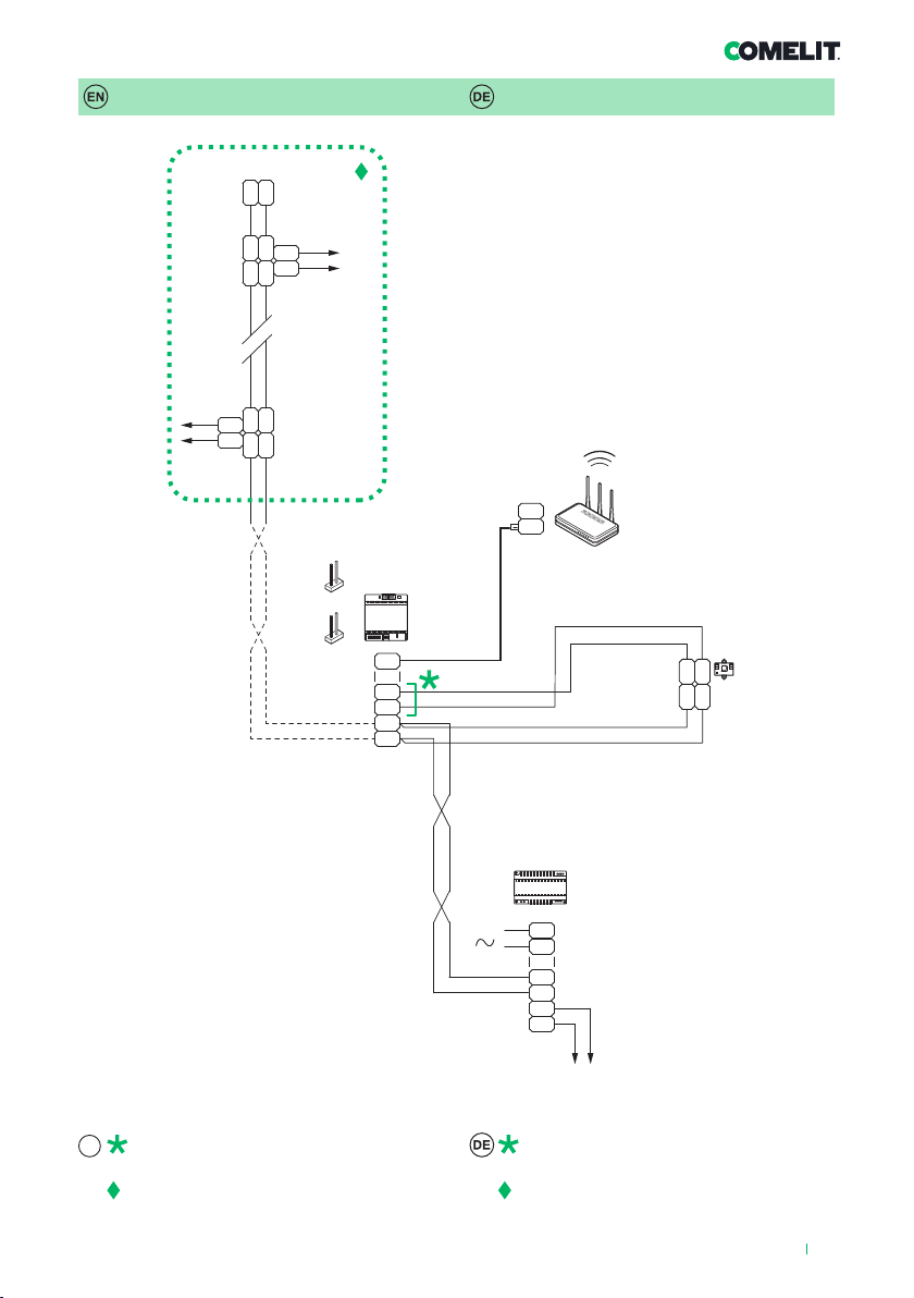
1406A4
2
Warning
• This Comelit product was designed for use in the creation of audio and video
communication systems in residential, commercial or industrial settings and
in public buildings or buildings used by the public.
• All activities connected to the installation of Comelit products must be
carried out by qualified technical personnel, with careful observation of the
indications provided in the manuals / instruction sheets supplied with those
products.
• Cut off the power supply before carrying out any maintenance procedures.
• Use wires with a cross-section suited to the distances involved, observing the
instructions provided in the system manual.
• We advise against running the system wires through the same duct as the
power cables (230V or higher).
• To ensure Comelit products are used safely: carefully observe the indications
provided in the manuals / instruction sheets and make sure the system
created using Comelit products has not been tampered with / damaged.
• Comelit products do not require maintenance aside from routine cleaning,
which should be carried out in accordance with the indications provided in
the manuals / instruction sheets. Any repair work must be carried out: for the
products themselves, exclusively by Comelit Group S.p.A., for systems, by
qualified technical personnel.
• Comelit Group S.p.A. does not assume any responsibility for: any usage
other than the intended use; non-observance of the indications and
warnings contained in this manual / instruction sheet. Comelit Group S.p.A.
nonetheless reserves the right to change the information provided in this
manual / instruction sheet at any time and without prior notice.
• This product falls within the scope of European product directive 2012/19/
UE concerning the management of waste electrical and electronic equipment
(WEEE). The device should not be disposed of as unsorted domestic waste
as it consists of various materials which can be recycled at relevant premises.
Contact your local authority to find out the location of the environmental
companies best suited to receiving the product for disposal and subsequent
proper recycling. The product is not potentially harmful to human health, as
it does not contain toxic substances as specified in Directive 2011/65/EU
(RoHS), but if abandoned in the natural environment may negatively impact
the ecosystem. Read the instructions carefully before using the product for
the first time. We advise against using the product for any purpose other than
its intended use, as improper use may present the risk of electric shocks.
This symbol on the product label indicates that the product
complies with the standards concerning waste electrical and
electronic equipment. Improper use of the equipment, or
abandoning it in the natural environment, may be punished by law.
Hinweise
• Dieses Comelit-Produkt ist für den Einsatz in Anlagen für Audio- und Video-
Kommunikation in Wohngebäuden, Gewerbe- und Industrieanlagen, in
öffentlichen Gebäuden und für den öffentlichen Gebrauch konzipiert.
• Die Installation der Comelit-Produkte darf nur durch Fachkräfte unter
genauer Befolgung der Anweisungen in den technischen Handbüchern / den
Bedienungsanleitungen erfolgen.
• Vor Eingriffen an der Anlage immer die Spannungsversorgung unterbrechen.
• Leiter mit einem für die Entfernung bemessenen Querschnitt verwenden und
die im Handbuch der Anlage aufgeführten Anweisungen einhalten.
• Es wird empfohlen, die Leiter der Anlage nicht in den Rohren der
Leistungskabel (230 V oder höher) zu verlegen.
• Sicherer Umgang mit Comelit-Produkten: Halten Sie sich strikt an die
Angaben in den technischen Handbüchern / den Bedienungsanleitungen.
Nehmen Sie keine Änderungen an der Anlage mit Comelit-Produkten vor
und vermeiden Sie Beschädigungen.
• Die Comelit-Produkte erfordern keine Wartungsarbeiten, abgesehen von der
normalen Reinigung, die entsprechend den Anweisungen in den technischen
Handbüchern / den Bedienungsanleitungen auszuführen ist. Eventuelle
Reparaturen dürfen für die Produkte nur durch die Firma Comelit Group
S.p.A., an der Anlage nur durch Fachkräfte ausgeführt werden.
• Comelit Group S.p.A. lehnt jede Haftung ab bei Schäden durch
bestimmungsfremden Gebrauch, Missachtung der Anweisungen
und Hinweise in dem vorliegenden technischen Handbuch / den
Bedienungsanleitungen. Comelit Group S.p.A. behält sich vor, jeder Zeit
und ohne Vorankündigung Änderungen an dem vorliegenden technischen
Handbuch / den Bedienungsanleitungen vorzunehmen.
• Dieses Produkt fällt in den Geltungsbereich der Richtlinie 2012/19/EU
über die Entsorgung von Elektro- und Elektronik-Altgeräten (WEEE). Das
Gerät darf nicht als unsortierter Hausmüll entsorgt werden, da es aus
verschiedenen Materialien besteht, die in geeigneten Anlagen recycelt
werden können. Erkundigen Sie sich bei der Stadtverwaltung, wo sich
geeignete ökologische Plattformen befinden, um das Produkt für ein
fachgerechtes Recycling entgegenzunehmen. Das Produkt ist nicht potenziell
gefährlich für die Gesundheit und die Umwelt, da es keine schädlichen
Stoe gemäß der Richtlinie 2011/65/EU (RoHS) enthält, kann in der Natur
jedoch negative Auswirkungen auf das Ökosystem haben. Lesen Sie die
Anleitung sorgfältig durch, bevor Sie das Gerät zum ersten Mal benutzen.
Verwenden Sie das Produkt nicht für andere als die vorgesehenen Zwecke,
da bei unsachgemäßer Verwendung die Gefahr eines Stromschlags besteht.
Dieses Symbol auf dem Etikett des Geräts zeigt an, dass dieses
Produkt den Vorschriften für Elektro- und Elektronik-Altgeräte
entspricht. Das Entsorgen der Geräte in der Natur oder ihre
missbräuchliche Verwendung ist strafbar.