GROUP S.P.A.
FT SB2 09 8
DEUTSCH
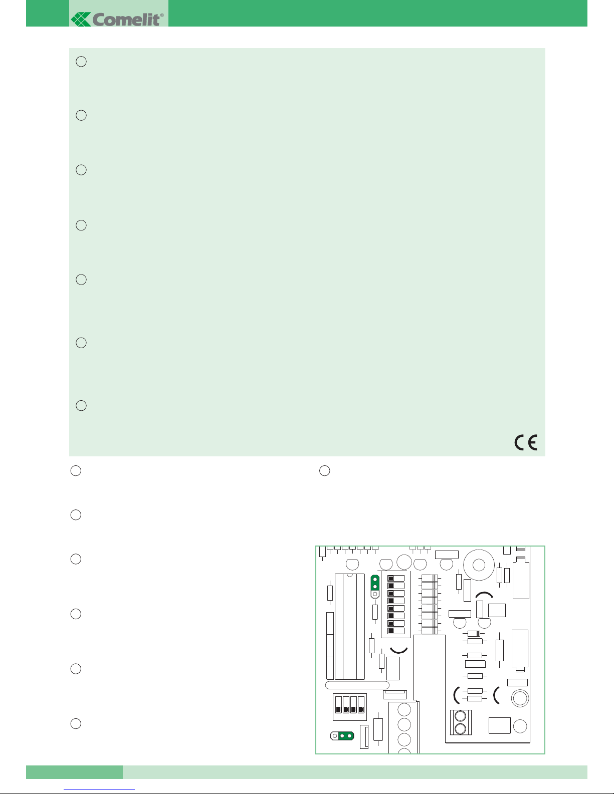
Innenstelle Art. 2410W/2B
Innenstelle der Serie Okay mit den Abmessungen 85x223x65 mm.
Die Innenstelle besitzt außerdem eine Türöffnertaste, eine Anzeige-Led und
zwei Tasten, deren Funktionen entsprechend der Anlage, in der sie
verwendet werden eingestellt werden können. Serienmäßig mit der
Ruffunktion von der Etage aus (siehe Variante A) und mit der
Rufwiederholung (siehe Variante B) ausgestattet. Es ist möglich bis zu 3
Innenstellen mit dem selben Anwendercode in der selben Anlage einzufügen.
Zur Einstellung des Anwendercodes siehe « Programmierung der
Innenstelle Art. 2408W/A, 2428W/A und Bügel Art. 4714W/2 » auf
MT/SB2/01 oder FT/SB/07. Es kann sowohl bei Simplebus1 Anlagen als
auch bei Simplebus2 Anlagen verwendet werden. Der Artikel ist werksseitig
für die Verwendung in Simplebus2 Anlagen eingestellt.
Siehe Hinweis auf Seite 2 für die Verwendung der Innenstelle Art.
2410W/2B in Simplebus1 und Bravo kit Anlagen.
Der Art. 2410W/2B ermöglicht bei Anlagen Typ Simplebus1 und
Simplebus2 die Verwendung der Funktionen Privacy, Doktor, Aktivierung
und Ruf Zentrale, sowie bei Anlagen Typ Bravo kit der Funktionen Privacy,
Doktor, Aktivierung und Interkommunikation Ein- und Zweifamilienhäuser.
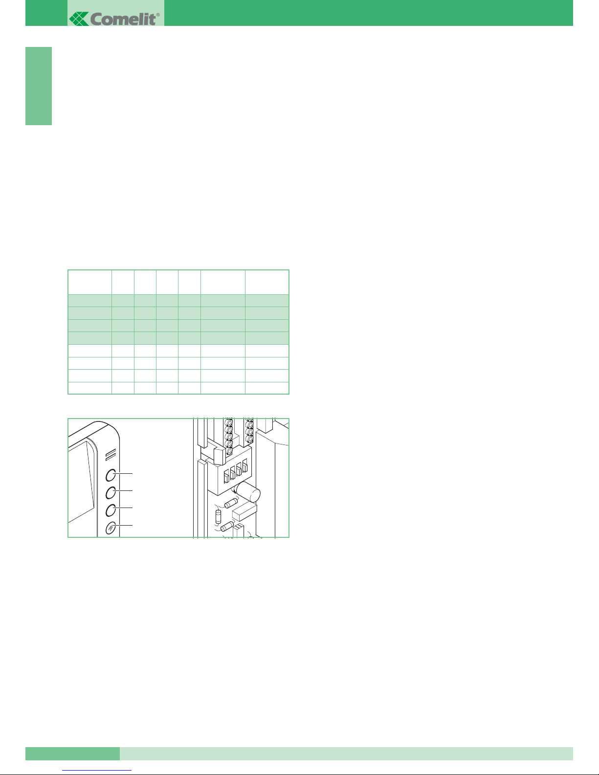
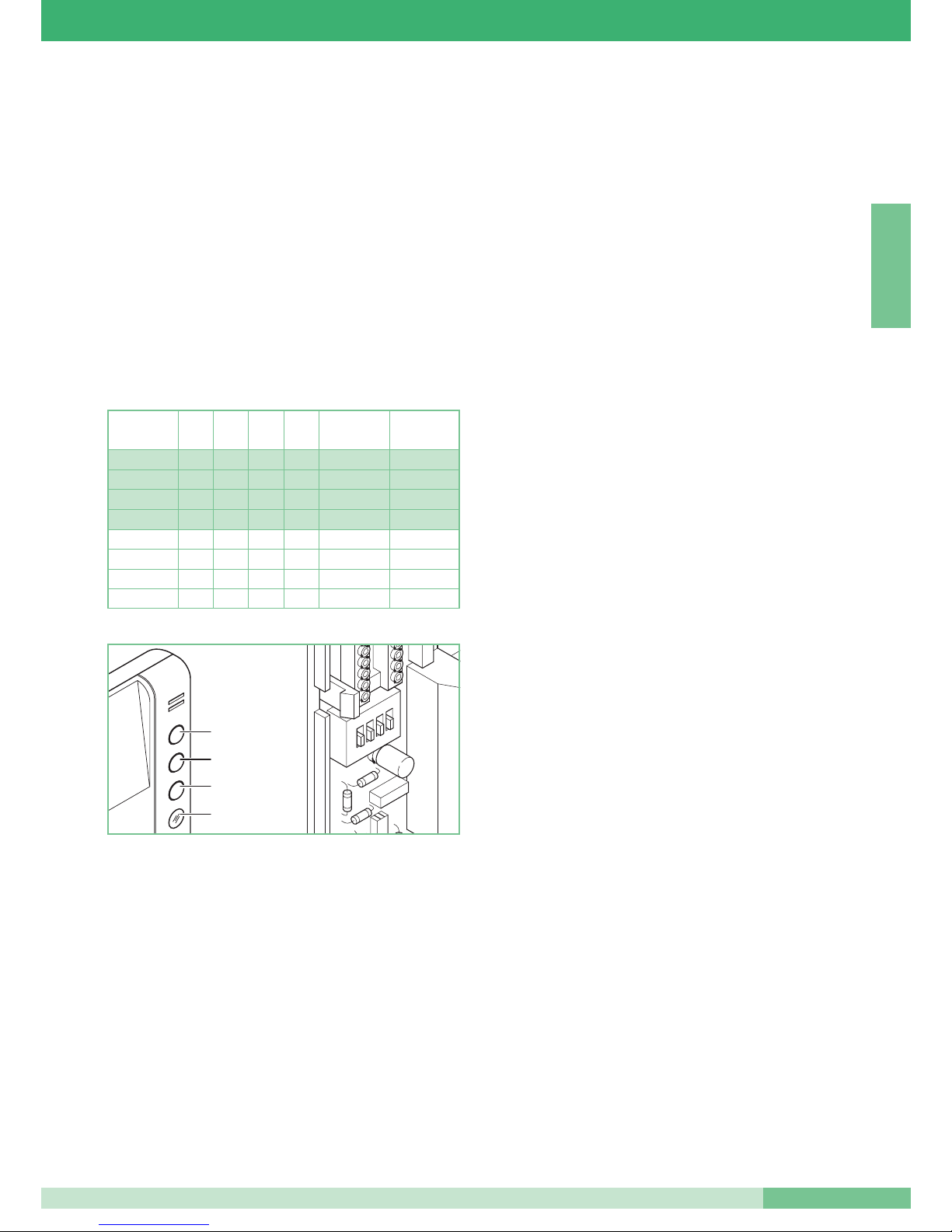
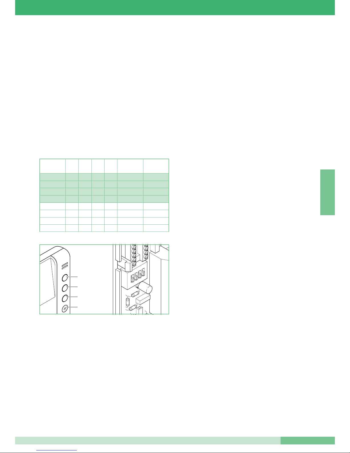
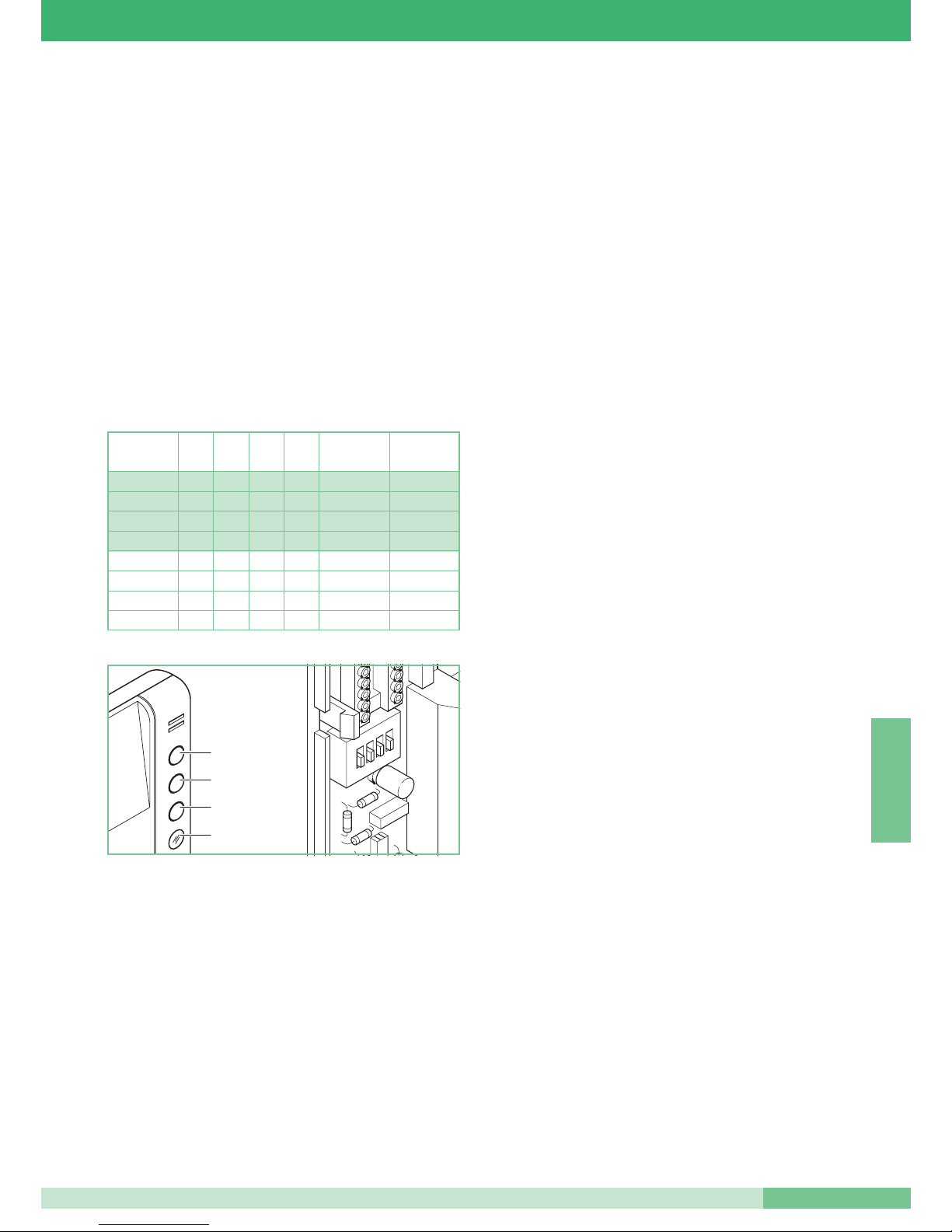
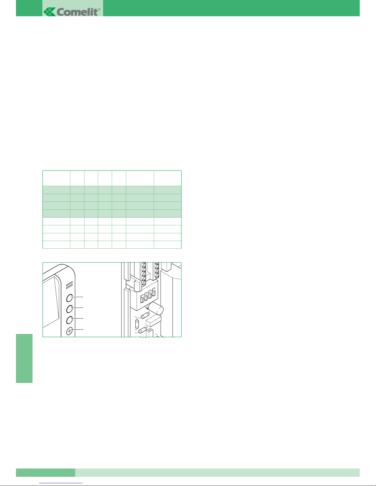
Die Regeln für die Einstellung der Dip-Schalter S2 für die Zuordnung der
Tasten sind in Tab. 1 angeführt.
Die Funktion Privacy ermöglicht, falls eingestellt, die vorübergehende
Abschaltung des Ruftons der Gegensprechanlage von der Außenstelle, von
der Portierzentrale.
Die Funktion Doktor ermöglicht zusätzlich zum Ausschalten der
Innenstelle, wie bei der Funktion Privacy, die automatische Betätigung des
Türöffners bei Anruf des Teilnehmercodes von der Außenstelle.
Die Freigabe oder Sperrung der Privacy- und der Doktorfunktionen erfolgt
durch 2 Sekunden langes Drücken der Taste 3 der Innenstelle Die
Aktivierung wird zusätzlich durch das Aufleuchten der Anzeige-Led
signalisiert. Falls mehrere Teilnehmer den gleichen Teilnehmercode
besitzen muss die Funktion Doktor nur bei einem der mit dieser Funktion
aktivierten Geräte eingestellt werden. Für den Einbau des Art. 2410W/2B in
Anlagen Typ Simplebus und Bravo kit siehe Schemata Abschn. A: SB/I1 -
SB2/01 - SB/J1.
Die Ruffunktion Aktivierung ermöglicht die Aktivierung des Relais im Art.
1256. Diese Funktion darf nur eingestellt werden, wenn ein Art. 1256 mit
eingestellter Funktion E (Aktivierung bei Taster) verwendet wird.
Siehe beiliegendes Technik-Merkblatt FT/SB2/02 für die Einstellung des
Moduls Aktivierungsrelais Art. 1256, damit sich dieses auf Befehl des
Tasters einschaltet.
Der Tasteranruf erfolgt durch Betätigen der Taste 2 oder Taste 3, je nach
Einstellung. Für den Einbau des Art. 2410W/2B in Anlagen Typ Simplebus
und Bravo kit siehe Schemata Abschn. A: SB/I1 - SB2/01 - SB/J1.
Die Funktion Ruf Zentrale ermöglicht bei Anlagen mit Portierzentrale Art.
1998 den Anruf derselben. Bei Anlagen ohne Zentrale Art. 1998 kann die
gleiche Funktion verwendet werden, um das Relais des Art. 1256 zu
aktivieren. Siehe beiliegendes Technik-Merkblatt FT/SB2/02 für die
Einstellung des Modul Aktivierungsrelais Art. 1256, damit sich dieses auf
Befehl des Anrufs der Zentrale einschaltet.
Der Anruf der Zentrale erfolgt durch Betätigen der Taste 2 der Innenstelle,
sofern der Dip-Schalter S2 korrekt eingestellt ist (siehe Tab. 1).
Für den Einbau des Art. 2410W/2B in Anlagen Typ Simplebus siehe
Schemata Abschn. A: SB/I1 - SB2/01 - SB/J1.
Die Interkommunikationsfunktion für Einfamilienhäuser kann nur in Bravo
kit Anlagen verwendet werden. Diese ermöglicht die Audiokommunikation
zwischen zwei Einheiten (Innenstellen und Video- Innenstellen), die auf den
gleichen Teilnehmercode eingestellt sind. Das Betätigen von P2 oder P3
aktiviert den Ruf zu den verbleibenden Stellen der gleichen Wohneinheit.
Der Rufempfänger muss den Hörer abnehmen, um so mit dem Anrufer zu
kommunizieren. Durch erneutes Auflegen des Hörers wird die
Kommunikation beendet. Ein Anruf von der Außenstelle hat immer Vorrang
über eine interne Kommunikation. In diesem Fall vernehmen die Benutzer,
die sich bereits in einer Konversation befinden, einen Ton, der dem Rufton
ähnlich ist, wenn der Ruf an sie gerichtet ist, andernfalls einen dreifachen
Signalton. Um auf den Ruf von einer Außenstation zu antworten, genügt es,
den Hörer von irgendeinem freien Apparat abzunehmen oder den Hörer
von einem Apparat, der zur Interkommunikation benutzt wird, aufzulegen
und wieder abzunehmen. Die Aktivierung der Kommunikation mit einer
Außenstation unterbricht die vorher laufende Interkommunikation.
Ein Anruf zur Interkommunikation hat keine Priorität vor einer Konversation
mit der Außenstation oder vor einem Anruf von dort. In diesem Fall blinkt
die LED während des Versuchs eines interkommunizierenden Anrufs einige
Sekunden lang, um zu signalisieren, dass das System belegt ist.
Die Interkommunikation in Einfamilienanlagen erfolgt durch Betätigen der
Taste 2 oder Taste 3, je nach Einstellung des Dip-Schalters S2 (siehe Tab.
1). Für den Einbau des Art. 2410W/2B in Anlagen Typ Bravo kit siehe
Schema SB/J1 im Abschn. A.
Die Interkommunikation in Zweifamilienhäusern kann nur in Bravo kit
Anlagen verwendet werden: Diese ermöglicht die Audiokommunikation
zwischen zwei Einheiten (Innenstellen und Video- Innenstellen), die nicht
auf den gleichen Teilnehmercode eingestellt sind. Das Betätigen der Taste
P3 aktiviert den Ruf zu den Stellen der anderen Wohneinheit. Wenn der
Empfänger des Anrufs den Hörer abnimmt, tritt er mit dem Anrufer in
Verbindung. Durch erneutes Auflegen des Hörers wird die Kommunikation
beendet.
Ein Ruf von einer Außenstation hat in jeden Fall Priorität vor einer
Interkommunikation. In diesem Fall vernehmen die Benutzer, die sich
bereits in einer Konversation befinden, einen Ton, der dem Rufton ähnlich
ist, wenn der Ruf an sie gerichtet ist, andernfalls einen dreifachen
Signalton. Um auf den Ruf von einer Außenstation zu antworten, genügt es,
den Hörer von irgendeinem freien Apparat abzunehmen oder den Hörer
von einem Apparat, der zur Interkommunikation benutzt wird, aufzulegen
und wieder abzunehmen. Die Aktivierung der Kommunikation mit einer
Außenstation unterbricht die vorher laufende Interkommunikation.
Ein Anruf zur Interkommunikation hat keine Priorität vor einer Konversation
mit der Außenstation oder vor einem Anruf von dort. In diesem Fall blinkt
die LED während des Versuchs eines interkommunizierenden Anrufs einige
Sekunden lang, um zu signalisieren, dass das System belegt ist.
Die Interkommunikation in Zweifamilienanlagen erfolgt durch Betätigen der
Taste 3, sofern der Dip-Schalter S2 korrekt eingestellt ist (siehe Tab. 1).
Für den Einbau des Art. 2410W/2B in Anlagen Typ Bravo kit siehe Schema
SB/J1 im Abschn. A.
Tab. 1