COMETA WAVE PLUS User manual

WAVE PLUS - USER MANUAL
COD.WPMEMG
REV 01
02/11/2011
DATA PRIMA EMISSIONE
Pag. 1 di 37
“WAVE PLUS”
MULTICHANNEL
ELECTROMYOGRAPH
USER MANUAL
Redaction:
SALES –M. DELLACORNA
GM –A. DELLACORNA
Check:
GM –A. DELLACORNA
Approval:
GM –A. DELLACORNA
Data: 24/02/2012
Revision: 01
Code: WPMENG
Revision:
Revision:
Approval Date:
Changes Description:
01
24/02/2012
Revision post IMQ review
The system is classified according to 93/42/CEE regulation
This device complies with Part 15 of the FCC Rules. Operation is subject to the following two
conditions: (1) this device may not cause harmful interference, and (2) this device must accept
any interference received, including such that may cause undesired operations.
Any change or modification not expressly approved by Cometa Srl for compliance could void
the user’s authority to operate the equipment.

WAVE PLUS - USER MANUAL
COD.WPMEMG
REV 01
02/11/2011
DATA PRIMA EMISSIONE
Pag. 2 di 37
Table of Contents
1. INTRODUCTION...................................................................................................................................................................... 3
2. DESTINATION AND CLASSIFICATION............................................................................................................................. 3
2.1 HOW TO USE IT........................................................................................................................................................................................5
3. WAVE PLUS SYSTEM COMPONENTS ............................................................................................................................... 6
3.1 FUNDAMENTAL,OPTIONAL AND ACCESSORY COMPONENTS............................................................................................................7
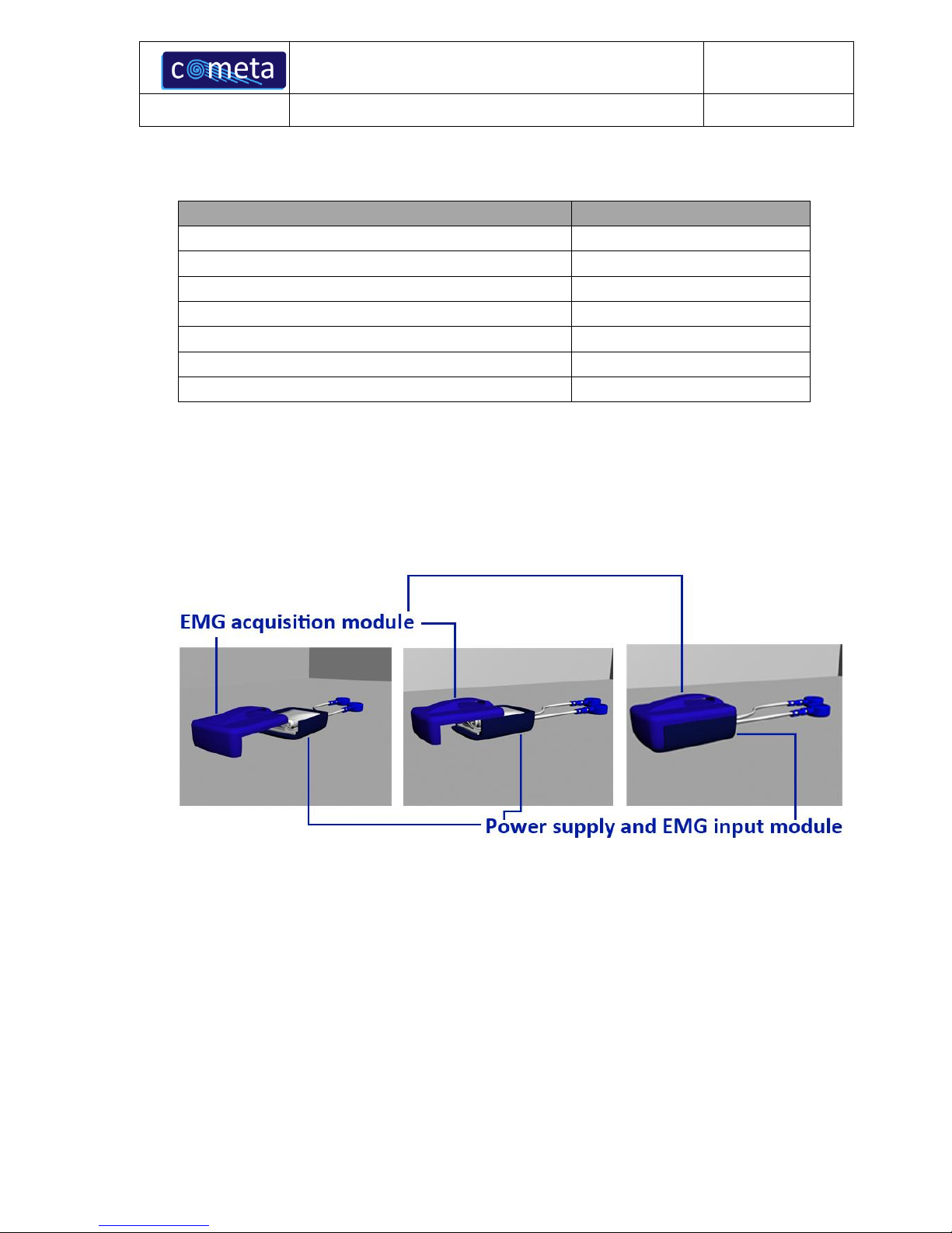
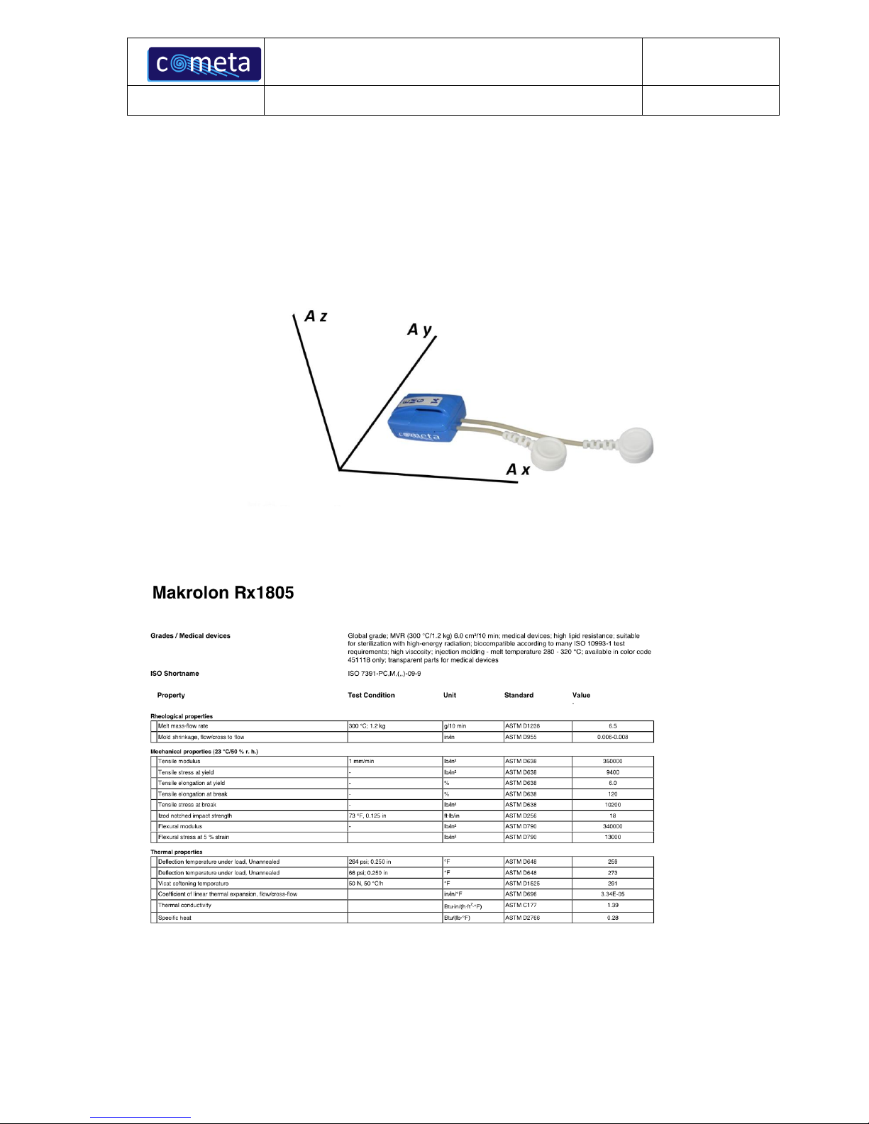
3.2 WIRELESS ELECTRODES.........................................................................................................................................................................7
3.3 BASE UNIT................................................................................................................................................................................................9
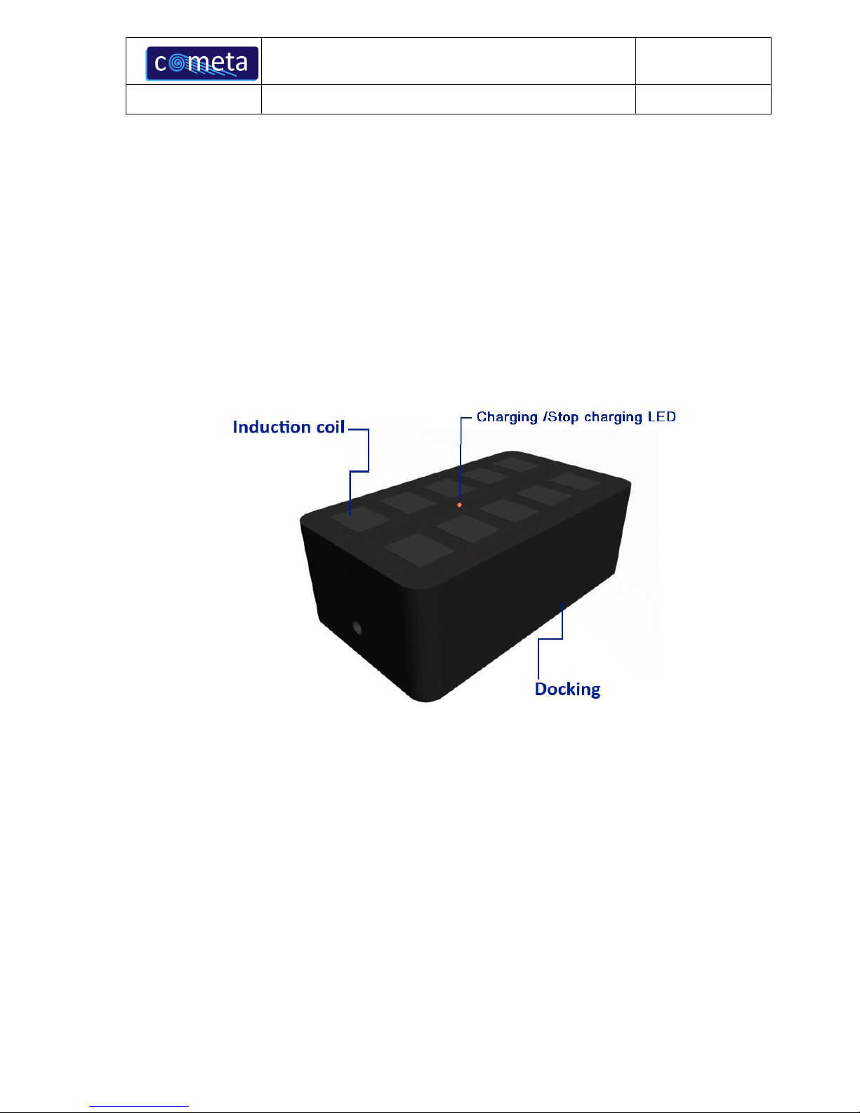
3.4 DOCKING MODULE ...............................................................................................................................................................................10
4. WAVE PLUS SYSTEM USE ..................................................................................................................................................11
4.1 ANALOG MODE .....................................................................................................................................................................................11
4.1.1 Supported external devices.................................................................................................................................................... 12
4.1.2 Layout of cable connections .................................................................................................................................................. 13
4.2 DIGITAL MODE......................................................................................................................................................................................14
4.2.1 External trigger..........................................................................................................................................................................15
4.2.1.1 Trig in............................................................................................................................................................................................................16
4.2.1.2 Trig out .........................................................................................................................................................................................................16
4.2.1.3 Strobe IO ......................................................................................................................................................................................................16
4.2.1.4 How to use the Trigger port...............................................................................................................................................................17
4.2.2 Supported external devices....................................................................................................................................................18
4.3 LED SIGNALLING DURING OPERATION.............................................................................................................................................19
4.3.1 Base unit LEDs:...........................................................................................................................................................................19
4.3.2 Electrode unit LED: ...................................................................................................................................................................19
4.4 PRE-GELLED ELECTRODES..................................................................................................................................................................19
4.5 ELECTRODES BATTERY RECHARGE ...................................................................................................................................................20
4.5.1 LED indicator of the charging module ..............................................................................................................................20
4.5.2 LED indicator of the electrodes............................................................................................................................................21
4.6 WARNINGS............................................................................................................................................................................................21
4.7 PIEZORESISTIVE SENSORS ..................................................................................................................................................................23
5. SYSTEM MAINTENANCE ....................................................................................................................................................25
5.1 REPAIRABLE PARTS.............................................................................................................................................................................25
5.2 REPLACEMENT OF ELECTRODE BATTERY.........................................................................................................................................26
5.3 ELECTRODE BATTERY CHARACTERISTICS........................................................................................................................................28
5.4 WARNINGS ABOUT ELECTRODES BATTERY......................................................................................................................................29
5.4.1 General warnings.......................................................................................................................................................................29
5.4.2 Warnings for battery disposal .............................................................................................................................................. 30
5.4.3 Warnings for device disposal ................................................................................................................................................ 30
5.5 REPLACEMENT OF WORN PARTS .......................................................................................................................................................30
5.6 WAVE PLUS CLEANING .......................................................................................................................................................................30
5.7 REFERENCES.........................................................................................................................................................................................31
6. LABELS ....................................................................................................................................................................................32
6.1 BASE UNIT:...........................................................................................................................................................................................32
6.2 BRIEF CASE WITH CHARGER:..............................................................................................................................................................32
6.3 INDUCTIVE CHARGER (INSIDE THE BRIEF CASE,UP TO TWO UNITS):..........................................................................................33
6.4 ELETTRODI:..........................................................................................................................................................................................33
7. TECHNICAL SPECIFICATIONS (WAVE PLUS 16 CH) .................................................................................................35
7.1 SUITABILITY..........................................................................................................................................................................................37

WAVE PLUS - USER MANUAL
COD.WPMEMG
REV 01
02/11/2011
DATA PRIMA EMISSIONE
Pag. 3 di 37
1. INTRODUCTION
Wave Plus system is an innovative multi-channel wireless surface electromyographic system with
accelerometers.
The leading specifications of this new system are:
Wireless and low-power electrodes for a quick patient set-up and for movements performed in total
freedom;
Acquisition of SEMG signal simultaneously with the accelerometer signal
Digital transmission via RF;
Receiver device equipped with analog and digital (USB port) data output for all channels;
Developed with high integration “SMD” technology;
Compatible with ISM standard –low power devices (ETSI, FCC, JAPAN);
Designed to be integrated with lab equipment for multipurpose acquisition systems.
2. DESTINATION AND CLASSIFICATION
Wave Plus is a system for the data collection of biologic signals; the main system feature is the absence
of cables between the transmitters on the patient and the data receiver/recording unit.
This allows the acquisition of EMG and accelerometer signal while patient is free to move.
This feature is very useful for clinical and scientific applications, for example in pathologic gait analysis
or in rehabilitation.
Low invasivity and high safety allow to use Wave Plus system for patients who tolerate the adhesive
electrodes and conductive gel for SEMG detection through medical electrodes.
Wave Plus system application areas are:
Neurology;
Physiatry and rehabilitation;
Orthopedy;
Ergonomics;
Sport medicine;
Veterinary.

WAVE PLUS - USER MANUAL
COD.WPMEMG
REV 01
02/11/2011
DATA PRIMA EMISSIONE
Pag. 4 di 37
Wave Plus system is classified according to CEI 60601-1:1998:
- The applied part is a BF type according to CEI EN 60601-2-40 regulation (icon):
- Second class device working with an external power supply providing power to internal peripheral
units; lithium rechargeable battery (icon):
-IPX0 protection degree of shells (NOT water proof);
-Functioning type: continuous.
Other graphic symbols on equipment:
-Ambient operating humidity range(graphic symbol):
-The device and its components must be disposed of according to regulations in the country of
use(graphic symbol):
-Ambient temperature range of operation(graphic symbol):
-Consult the user manual for instructions on operating (graphic symbol):

WAVE PLUS - USER MANUAL
COD.WPMEMG
REV 01
02/11/2011
DATA PRIMA EMISSIONE
Pag. 5 di 37
2.1 How to use it
To use Wave Plus, two pre-gelled disposable electrodes for each channel have to be applied to the
subject. The EMG acquisition module is applied on the surface electrodes using a snap connector.
If required by the exam, piezoelectric sensors are applied for the identification of plantar supports; the
foot-switch acquisition module is applied to the sensor by the appropriate cables.
To use the Wave Plus system only as an inertial acquisition system, that is by using only the
accelerometers included in the probes and not the EMG signal acquisition, it is sufficient to attach or
strip the probes in the designated place, without any need for pre-gelled electrodes.
Wave Plus system can be used by doctors, paramedics and technicians.
To use Wave Plus system, please, read carefully the instructions in the relative chapter.

WAVE PLUS - USER MANUAL
COD.WPMEMG
REV 01
02/11/2011
DATA PRIMA EMISSIONE
Pag. 6 di 37
3. WAVE PLUS SYSTEM COMPONENTS
The following representation shows all Wave Plus components.
The standard configuration of the system is composed of:
EMG / accelerometer wireless modules, whit snap connections to the electrodes;
two wireless modules, to transmit gait cycle events (footswitches);
a receiver unit;
a docking box to recharge the wireless modules.
Wireless modules are equipped with an internal rechargeable battery. The modules communicate with
the PC through the base unit thanks to a bi-directional link working at 2400 MHz.
When not used, modules should be displaced in the dedicated areas of the docking box to receive energy
for battery recharge.
An automatic system for power saving optimise battery life during the phases in which the electrodes
are not used.

WAVE PLUS - USER MANUAL
COD.WPMEMG
REV 01
02/11/2011
DATA PRIMA EMISSIONE
Pag. 7 di 37
3.1 Fundamental, optional and accessory components
3.2 Wireless electrodes
The Wave Plus system module is composed of two parts:
The conditioning signal module, with active circuitry for signal radio-transmission;
Power supply module and I/O interface including rechargeable battery, recharge coil, and the
connections to the detection points.
SYSTEM ELEMENTS
Classification
Base Unit
Fundamental
Friwo power supply FW7555M/09
Fundamental
Docking base
Fundamental
EMG Electrodes
Optional
USB Cable
Optional
Analogue Cable
Accessory
Foot-switch Electrodes
Accessory

WAVE PLUS - USER MANUAL
COD.WPMEMG
REV 01
02/11/2011
DATA PRIMA EMISSIONE
Pag. 8 di 37
The power supply module is connected to the acquisition unit through a sliding mechanism; the unit
disassembly should be done only during maintenance (exhausted battery or electric wire deteriorated).
In these cases follow the instructions in the chapter “Replacement of electrode battery”.
Each EMG module (total of 16) is also equipped with a tri-axis accelerometer, able to capture the
minimum movement of the body in space. The disposition of the accelerometer sensors is the following:
The electrodes are realized with fully bio-compatible plastic produced by Bayer. Below teh factsheet of
the material used for the electrodes casings:
In order to apply the electrodes on the patient’s skin it is necessary to use bi-adhesive tape suitable to be in
contact with the skin and therefore certified to that use, such as the 3M 1522 Double Coated Medical Tape
produced and certified by 3M.

WAVE PLUS - USER MANUAL
COD.WPMEMG
REV 01
02/11/2011
DATA PRIMA EMISSIONE
Pag. 9 di 37
3.3 Base unit
The base unit has a front panel with status LEDs.
The signals are:
LED off: the electrode is non active;
LED on: green light: the electrode is active.
The front panel has also a further green LED indicating the on/off status of the base unit.
On the rear panel:
on-off switch;
jack for the external power supply
female port SCSI 68 pin for analog outputs;
jack for the connection of the external trigger;
USB port to connect the host PC;
LED showing presence of supply;
LED for auxiliary functions (CHG) –not active

WAVE PLUS - USER MANUAL
COD.WPMEMG
REV 01
02/11/2011
DATA PRIMA EMISSIONE
Pag. 10 di 37
The base unit has a RF transceiver at 2,4 GHz, a microprocessor for data synchronisation and separa-
tion, D/A converter, a USB port to connect the host PC.
The base unit can be supplied with built–in antennas (as standard), or with external antennas. The appli-
cation of the external antennas allows the extension of the useful working area of the system.
3.4 Docking module
When not in use, wireless electrodes should be in the docking module to recharge the batteries.
The recharge occurs by coils, attached to the electrodes support base and on the layer of the charger; the
energy transfer occurs via induction.
Coils on the docking are excited to resonance by adequate impulses in frequency and amplitude; when
the electrode is on the docking, there is an induced alternate current in the electrode coil that will be sent
to the battery for its recharging.
The docking module has a LED status indicator of the charger; during charging the LED is orange,
when charging is over, the LED turns to green, as described below.

WAVE PLUS - USER MANUAL
COD.WPMEMG
REV 01
02/11/2011
DATA PRIMA EMISSIONE
Pag. 11 di 37
4. WAVE PLUS SYSTEM USE
Wave Plus system can be used in two different configurations:
Linked to an A/D converter for visualisation and analog storage of EMG and basography
data, adopting external devices;
Linked to a PC through the USB port for visualisation, system control and digital data stor-
age of EMG and basography (third party software not produced by Cometa srl).
The two configurations can be used simultaneously.
4.1 Analog mode

WAVE PLUS - USER MANUAL
COD.WPMEMG
REV 01
02/11/2011
DATA PRIMA EMISSIONE
Pag. 12 di 37
To operate the system:
1) Connect J26 connector of Wave Plus by cable (analog output) to the analog A/D interface of
the external device;
2) If required, connect the trigger cable to the external device. Check trigger electric features
(voltage and timing) adopted by the system (see “Technical specifications” chapter);
3) Connect Wave Plus power supply and switch on the system.
The system can be powered only with Friwo FW7555M/09 power supply provided by the
producer; the use of other power supply units can cause electric shock and damage the
system.
If used in analog mode, the system does not require a Personal Computer; after switching on the base
unit, EMG and basographic signals are available in continuous on analog output connector J26.
4.1.1 Supported external devices
The Wave Plus system can be connected to analog devices commonly used in clinical and scientific en-
vironments; these are the features required by systems:
At least 8 or 16 EMG data collection channels, configured for signals with Zout = 100 ohm and
an amplitude of ± 2,5 V;
At least two analog channels to acquire footswitches, configured for signals with Zout = 100
ohm and an amplitude of + 2,5 V;
If also accelerometer signals has to be transmitted to the analog device, another24 or 48 data
collection channels (3 for each tri-axis accelerometer) are needed;
It complies with IEC 60950.
The use of external devices non-complying with IEC 60950 can cause electric shock and
damage the system. The external devices connected to Wave Plus with an analog
interface, do not have any control over the system acquisition or settings. Any third party
system used with Wave Plus has to be placed out of the patient area, and must be
powered via an isolation transformer or power supply conform to the IEC 60601-1.

WAVE PLUS - USER MANUAL
COD.WPMEMG
REV 01
02/11/2011
DATA PRIMA EMISSIONE
Pag. 13 di 37
4.1.2 Layout of cable connections
Pin out of the analog output connector.
X2
Z4
Z9
EMG_CH5
Y2
X3
X5
EMG_CH4
Z2
X9
EMG_CH3
1
2
3
4
5
6
7
8
9
10
11
12
13
14
15
16
17
18
19
20
21
22
23
24
25
26
27
28
29
30
31
32
33
34
35
36
37
38
39
40
41
42
43
44
45
46
47
48
49
50
51
52
53
54
55
56
57
58
59
60
61
62
63
64
65
66
67
68
J26
CONN SCSI 68-R
Y3
X4
EMG_CH2
Y5
Z3
EMG_CH1
Y4
X5
Y9
Z4
Y16
Y5
Z15
Z5
Z14
Y6
X15
Z6
X16
Z13
Y7
X6
X14
Z7
X13
Y8
Z16
Y6
Z8
X7
Y15
FSW_A
Y9
Z6
X1
Y14
Z9
X8
Z5
X7
Y10
Y13
Z10
X6
X9
Y7
Z1
Y11
GND_ANA
Z7
Z11
X10
EMG_CH16
X2
EMG_CH15
Y12
EMG_CH14
X8
Z12
X11
EMG_CH13
Y2
Y13
EMG_CH12
Y8
Z13
X12
EMG_CH11
X3
Y14
EMG_CH10
Z8
Z14
EMG_CH9
X13
FSW_B
Z2
Y15
X11
Z12
Z15
X14
Z3
Y3
Y16
Y12
Z10
Z16
X15
GND_ANA
X4
X1
X12
Y10
EMG_CH6
X16
Z11
Y4
EMG_CH8
X10
EMG_CH7
Z1
Y1

WAVE PLUS - USER MANUAL
COD.WPMEMG
REV 01
02/11/2011
DATA PRIMA EMISSIONE
Pag. 14 di 37
4.2 Digital mode
To operate the system:
1. Connect Wave Plus USB cable to the PC USB port. The power is taken directly from the USB
port;
The use of Personal Computer non-complying with IEC 60950 can cause electric shock
and damage the system. The use of Personal Computer non-complying with IEC 60950
is allowed using a medical class insulation transformer to power the PC.
2. If required, connect the trigger cable to the external device, after checking trigger electric fea-
ture (voltage and timing) adopted by the system (read “Technical specifications” chapter);
3. Connect, if required, the Wave Plus power supply and switch on the system;

WAVE PLUS - USER MANUAL
COD.WPMEMG
REV 01
02/11/2011
DATA PRIMA EMISSIONE
Pag. 15 di 37
Use only the supplied power supply FRIWO FW7555M/09 . The use of other units
could lead to electric shock or damage to the instrumentation.
4. open the control program and follow the third party software indication for data graphic render-
ing and digital data collection.
The operation of the system Wave Plus is now under the control of the Personal Computer. Refer to
the User Manual supplied by the manufacturer of third party software for the description of the oper-
ational commands. The following table gives the references:
Software Code: NA
Release: NA
Manufactured by: NA
When operating in digital mode, the device is powered directly from the PC via the
USB interface; for correct operation, the connection must provide the rated current
provided by the USB II specification(500mA). In this case, the use of the external
power supply is optional, and the computer must be powered via an isolation trans-
former or power supply according to IEC60601-1.
You can also use a personal computer equipped with USB ports with reduced current
(100mA), in which case you must connect, in addition to the USB cable, the external
power supply.
4.2.1 External trigger
Wave Plus has a connector for external trigger of data capture. External trigger lines are
not insulated from the Wave Plus system ground.
The use of external devices not complying with IEC 60950 can cause electric shock and
damage the system.
Pin out of the trigger jack:

WAVE PLUS - USER MANUAL
COD.WPMEMG
REV 01
02/11/2011
DATA PRIMA EMISSIONE
Pag. 16 di 37
TRIG_IN
STROBE I/O
GND
1
2
3
4
J22
TRIG_OUT
4.2.1.1 Trig in
Data capture can be synchronised with an external trigger signal. If required, connect the trigger cable to
the external device after checking that the trigger control complies with the electric features required by
the system (see “Technical Specifications”).
Trigger logic:
1) Data acquisition if the “trigger in” signal is at “1” logic level
2) No data acquisition if the “trigger in” signal is at “0” logic level
The default condition of the line is “1”.
Storing data on the hard disk of your computer is managed by the acquisition and processing SW; for
information about the data file format and processing, refer to the user manual of the SW.
4.2.1.2 Trig out
A “trigger out” channel shows the system status:
1) “Trig out” signal at “1” logic level when the system is acquiring
2) “Trig out” signal at “0” logic level when the system is not acquiring
4.2.1.3 Strobe IO
The line "Strobe IO" is used for synchronization of a second Wave Plus receiver for the expansion to
32channelsof the system. This line is used by the system and should only be connected to another Wave
Plus unit, according to information provided by Cometa.

WAVE PLUS - USER MANUAL
COD.WPMEMG
REV 01
02/11/2011
DATA PRIMA EMISSIONE
Pag. 17 di 37
4.2.1.4 How to use the Trigger port
Usually, the Triggers (Input and Output) are used when the Wave Plus system is interfaced with third-
party devices by digital port (USB). Here below, you can see the typical configuration in order to obtain
the synchronisation between the Wave Plus EMG system and a third-party device by using the Trig
In/Out port.
For further details on how to use the Trigger option, please refer to the third party software manual
provided by the producer of the software used.
However, it is some way possible to synchronize the Wave Plus EMG system and a third-party device
also using the analog EMG signals. Here below, there is a simple scheme which describes how to
implement this type of synchronism.
We can consider two possible modes for synchronous recording. In the first case, we assume that the
third-party device is able to control the synchronous acquisition by using its own “internal
synchronisms” mechanism; in this case the synchronisms will be totally handled by software/firmware
of the third-party device self. In the second case, we assume the third-party acquisition device must
“read” a trigger signal or record a “start” event into the acquisition data streaming (e.g. the event
related to the TMS stimulation).
In this latter case, we suggest to record both, the signals coming from the Wave Plus analog output and
the trigger signal, using the same A/D converter. In that way, not only the Wave Plus data, but also the
Acquisition
system
(accelerometer, ba-
ropodometer, etc.)
PC with
dedicated
software
Wave Plus
PC with
dedicated
software
Trig In/Out
USB Data
Digital Da-
ta
Third-party acquisition system
Wave Plus EMG
system
Acquisition
system
(accelerometer, ba-
ropodometer, etc.)
PC with
dedicated
software
Wave Plus
Wave Plus analogue
data
Digital da-
ta
A
/
D
Trig
Out
Wave Plus Trig Out
Wave Plus digital
data
Third-party acquisition system
Wave Plus system
U
S
B
PC with
dedicated
software

WAVE PLUS - USER MANUAL
COD.WPMEMG
REV 01
02/11/2011
DATA PRIMA EMISSIONE
Pag. 18 di 37
event of the beginning and the end of the data acquisition or, in general, a temporal reference event
(e.g. the timing of the TMS stimulation) can be directly saved into the same data streaming.
The scheme above shows the required connections to realise this type of synchronism in case:
1. The third-party device is working as master: red connection;
2. The Wave Plus system is working as master: blue connection
1
.
NOTE THAT if you want synchronize the Wave Plus system with third-party devices collecting the
EMG signals from the Wave Plus analogue port, you should also consider the 13 ms delay related to
the Wave Plus analogue output. In this case you should correct the recorded data in order to remove the
13 ms delay. NOTE THAT the 14 ms delay is constant and it can be easily removed by shifting the
temporal sequence in the following way:
NOTE THAT the delay does not produce a loss of acquired data at all.
Please, for further details contact Cometa.
4.2.2 Supported external devices
Wave Plus system can be connected to any PC with USB interface; these are the features required by
systems:
Type 2 USB interface
Windows 2000 or XP
VGA graphic card with a resolution of at least 1024 x 768
Minimum ram memory, 512 MB
Minimum processor frequency, 800 MHz
Minimum hard disk, 20 GB
1
In this case, it’s necessary to use also the dedicated software in order to produce the trigger signal.
Unrecorded sequence
Recorded sequence
Unrecorded sequence
Trigger Off
Trigger On
Trigger Off
Unrecorded sequence
Recorded sequence
Unrecorded sequence
14ms

WAVE PLUS - USER MANUAL
COD.WPMEMG
REV 01
02/11/2011
DATA PRIMA EMISSIONE
Pag. 19 di 37
The Personal Computer linked with the Wave Plus system has to comply with IEC 60950
regulation and has to be placed outside the patient’s area. The use of Personal Computer
non-complying with IEC 60950 is allowed using a medical class insulation transformer to
power the PC. The software (produced and commercialized by third parties) has to com-
ply with the CE93/42 regulations for medical devices.
4.3 LED signalling during operation
4.3.1 Base unit LEDs:
During Wave Plus functioning, LEDs are used to indicate the functioning status of the system.
On the base unit front panel there are eighteen bicolour LEDs:
-LED off: the correspondent electrode is in stand–by (non active);
-LED on, green light: the electrode is on;
-LED on, orange light: the electrode is on and the battery is low.
4.3.2 Electrode unit LED:
On the EMG unit there is one LED:
-LED off: the electrode is in stand–by condition (not active);
-LED on, green light: the electrode is on and recognised by the receiver unit;
-LED blinking green light: the electrode is on and the battery is low.
The LED of the transmitting module, when the electrode is placed on the charging cradle, also carries an
indicator function of the charging phases. In this case the color of the LED is orange. For more informa-
tion, refer to the battery charger chapter.
4.4 Pre-gelled electrodes
The Wave Plus system can be used with single-use pre-gelled electrodes equipped with snaps. Pre-
gelled electrodes are available in different dimensions, and may be purchased through local distributors
of consumable medical accessories.
To apply electrodes see the information provided by the manufacturer.

WAVE PLUS - USER MANUAL
COD.WPMEMG
REV 01
02/11/2011
DATA PRIMA EMISSIONE
Pag. 20 di 37
Warning: the quality of the EMG signal acquired by the Wave Plus system is linked to the quality of
the contact between electrode and skin; to obtain best results:
1. Use pre-gelled electrodes certified for a medical use and complying with the 93/42/CEE
regulation;
2. Do not use pre-gelled electrodes beyond the expiration date or with dry conductive gel;
3. Do not re-use the same electrode;
4. Do not use the electrode after having already applied it;
5. For long data acquisition periods, check the electrodes adhesive;
6. Apply electrodes only on undamaged skin and verify that their removal does not cause any
damage.
4.5 Electrodes battery recharge
To recharge the electrode batteries, put the electrode in the appropriate slot in the recharging module;
then power on the recharging module and wait for the signal that indicates the end of the recharging pe-
riod.
The jack socket for the power supply is accessible on the left side of the briefcase.
The charging module is equipped with an eight hours timer, after which the charge is automati-
cally stopped. This allows the unlimited permanence of electrodes into their respective hous-
ings, without the risk of overload the batteries.
To reset the timer and start a new charge cycle, you must disconnect the power jack and then
reconnect it.
4.5.1 LED indicator of the charging module
The operation of the charging module is indicated by a bicolor LED placed in the center of the unit;
alerts are:
1)Led Orange: the charger is on and the electrodes placed in the charging slots are subject to
charge;
2)LED green: the unit has completed the eight-hour charge cycle.
It is recommended to leave the case open during the recharge of the electrodes
units.
Table of contents
Popular Medical Equipment manuals by other brands

Rhythm Healthcare
Rhythm Healthcare LM5BA manual

BMC
BMC Oratect HM 15 reference guide

MHC Medical Products
MHC Medical Products SureLife Clearwave II user manual

Otto Bock
Otto Bock Kenevo 3C60 introduction

Shenzhen Roundwhale Technology
Shenzhen Roundwhale Technology R-C3 instruction manual

Nasco
Nasco Life/form LF00958U instruction manual