Comfort Company BodiLink E0955 User manual

USER GUIDE
& MANUAL
COMFORTCOMPANY.COM
BODILINK®HEAD SUPPORT
UM-BODILINK-HEAD-SUPPORT REV0218

2INTRODUCTION www.comfortcompany.com
At Comfort Company we are dedicated to creating and
manufacturing seating and postural support systems
designed for people with a wide range of rehabilitation
needs. Whether for pediatric, geriatric, or bariatric needs
we are committed to providing our customers with quali-
ty products designed for comfort, durability, and ease of
use. Our vision is to lead in the development, manufac-
turing, and delivery of the most innovative seating and
positioning products which provide the highest level of
comfort, functionality, and quality of life for the user.
1.800.564.9248
406.522.8563
customerservice@comfortcompany.com
www.comfortcompany.com
Customer Service
Bozeman, Montana
CONTACT INFORMATION
BEFORE USE
ABOUT US CONTENTS
Manufacturing
New Berlin, Wisconsin
Thank you for choosing COMFORT COMPANY®
NOTE: “We,” “Us” and “Our” refers to Comfort Company. “You” refers to the product purchaser or user.
SAFETY GUIDELINES
Symbols 3
General Safety 3-4
Intended Use/User 4
Parts Detail 5
INSTALLATION & SET UP
Attachment To Back Supports (any hardware) 6-12
Posterior Mounting Block 6
Anterior Mounting Block 7
Acta-Relief™Mounting Bracket 8
Posterior Mounting Block to Acta-Relief™back
support with Compass®Power Mount 9
Permobil®A Mounting Block (23-28”H, Uni-Track) 10
Permobil®B Mounting Block (20”H Backs) 11
Quantum®Mounting Block (TRU-Comfort2Backs) 12
Adding a Link to the GT Hardware 13
Adding a Link to the PT Hardware 14
Installing Tool-Less Wing Lock on PT Hardware 15
Connecting Hardware to Support Pads (any style) 16
Adjustments 16-20
Support Pad Positioning (any pad and hardware) 16
GT Style Hardware 18
PT Style Hardware 19
Finishing Installation (any hardware) 20
CLEANING AND MAINTENANCE
Cleaning 21
Inspection 22
Reuse 22
Storage 22
Disposal 22
WARRANTY AND REPLACEMENT
Lifetime Guarantee 22
Replacement Procedure 22
COMMENTS
15
Back
Cover
The appropriate Comfort Company positioning product
is intended to improve every day user function and com-
fort while providing support and stability for a variety of
rehabilitation needs. However, prior to using any Comfort
Company support, it is important that each individual be
assessed by a qualied healthcare professional for but not
limited to, mobility, nutrition, current condition, goals, and
health history. In addition to this initial assessment, individ-
uals should be regularly monitored by a health care profes-
sional for any changes in their condition.
This user guide and manual is for reference purposes only
and is not intended to substitute for advice given by a phy-
sician or other licensed healthcare professional. You should
not use this information for self-diagnosis or self-treatment
of a health problem or condition. Contact your healthcare
provider immediately if you suspect that your health prob-
lem or condition has changed or worsened.
Before using, make sure that you are properly trained to
operate the equipment for its application. Failure to do so
could lead to discomfort, injury or damages.

3
SAFETY GUIDELINES
SAFETY GUIDELINES
SAFETY SYMBOLS
GENERAL SAFETY
PLEASE NOTE
CARE SYMBOLS
Warning!
Prohibited!
Wash Cover Only -
Warm Cycle (Maximum Temperature)
Do Not Bleach
No Smoking
Do Not Expose to sources of excessive heat such as open ame or spark.
Bleach Okay
Tumble Dry Low
Do Not Tumble Dry, Steam Clean or
Autoclave
Air Dry Only
Hang to Dry
Do Not Iron
Antibacterial or Disinfectant Spray
Detailed cleaning instructions on page 21
Wipe with Water Only
Do Not Wash
Hand Wash
Do Not Cut
or Puncture
Although this product meets ammability requirements, we do not
recommend smoking while using this product. Damage from smoke and
ame is not covered by the lifetime warranty. You must consider additional
safety precautions when choosing to smoke while using this product.
Avoid sharp objects. Do not modify the product. Doing so will void its
warranty and may lead to personal injury or alter the effectiveness of the
product by increasing the risk factors for skin breakdown and/or instability.
Indicates actions that should NOT be performed at any time under any
circumstance. These actions could result in personal injury and/or damage
to the product or equipment being used.
Without following the specied procedure, this indicates potentially
hazardous conditions that could lead to personal injury, inadequate
performance, product damage or malfunction.
You must READ and FOLLOW all instructions, notes and warnings included in this
manual. Understanding how to care for your product is the key to safe and proper
use. Share this information with all caretakers to help them meet your healthcare
needs and ensure your safety.
Check packaging and inspect all parts for damage before use. DO NOT USE if dam-
aged and contact Comfort Company immediately for further instruction. Check reg-
ularly for loose components and tighten as necessary. Contact Comfort Company if
wear or damage is noted.
During the rst few hours of use, a healthcare professional should be available to
observe skin condition and assess the likelihood of skin breakdown.
During regular use, periodically check for skin discoloration and/or irritation. If discol-
oration should occur and not disappear after 30 minutes of non-use, discontinue use
and consult with your healthcare provider immediately.
DO NOT place anything in between the user and the product. Additional materials
may reduce the effectiveness of the product and increase risk factors for skin break-
down and instability.
Always use the cover and base with any inserts as a complete assembly. Never use a
cover other than one intended for your specic product and size.
Installing alternate parts to your wheelchair may change the intended structure and
function of the equipment. Be sure to assess the need for additional safety features
for your chair such as anti-tip bars or other available options in order to maintain
stability during use. Use this manual in conjunction with the user manual that came
with your chair to ensure safety guidelines are being met.
Comfort Company cannot be held responsible for damages or injury due to misuse
of the product or failure to follow instructions provided in this manual. Please contact
us if you require further assistance in understanding cautions, warnings or instructions
for using or maintaining your product.
The directions provided will help to maintain and extend the
life of your product and ensure it is covered by the Comfort
Company Lifetime Guarantee. Please see complete warranty
information on page 22.
The information in this manual was gathered and recorded with
the latest specications available at the time of publication. Due
to our continued effort to reassess and improve our products,
information found in this manual such as drawings and notes may
vary slightly from the product that you purchased. We reserve the
right to make changes to products as they are deemed neces-
sary. To check for the latest version of this manual please visit us
at www.comfortcompany.com.

4SAFETY GUIDELINES - INSTALLATION & USE www.comfortcompany.com
COMFORT-TEK™ fabric cover is uid-resistant, easily cleaned at any time
and soft to the touch. Comfort-Tek™fabric has stretch which helps alleviate
pressure and conforms to both support pad and user.
STRETCH-AIR™fabric cover is 2-Ply designed to be breathable on the
surface for comfort while the bottom layer is uid-resistant for cleanliness.
The multi-directional stretch allows for optimal conforming to the user and
support pad shape.
GLIDEWEAR®fabric cover is intended for maximum hair and skin protec-
tion by reducing shear. Recommended most for those with abnormal tone
causing involuntary movements, difcult postures and frequent repositioning
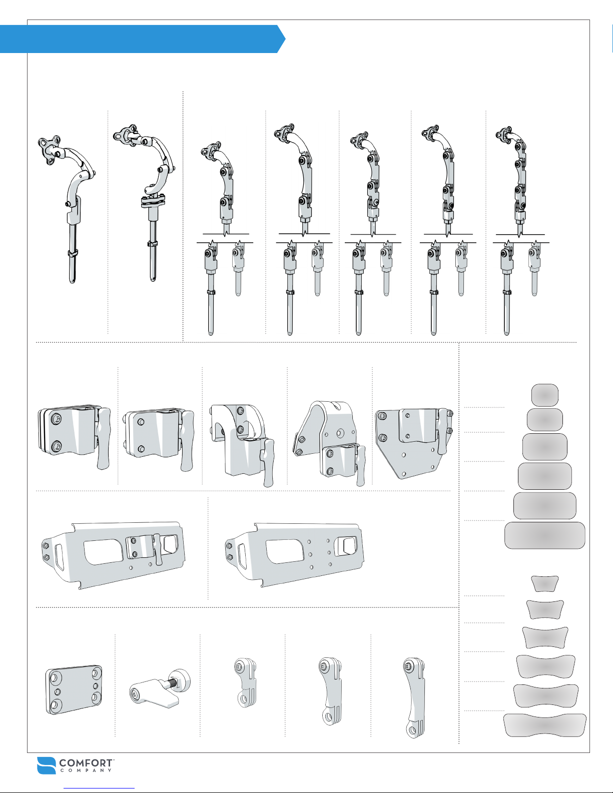
BodiLink® head support is intended for those with positioning and support needs as deemed necessary by a qualied healthcare professional.
BodiLink®head support offers a wide variety of available positions to accommodate user rehabilitation needs and goals while allowing for function and
comfort. The sizes available and range of adjustability t pediatric to full grown users and should be matched by the healthcare provider to suit the user
needs. Adjustments or replacement components may be necessary as changes in condition occur or to accommodate developments such as growth.
All fabrics used in BodiLink®Head Support covers are latex-free.
Comfort-Tek™fabric is used on all head support pad covers along
the outer edge.
BodiLink® Premium Head Support Pads come in two levels of rm-
ness (soft and extra soft). Both use a layer of Viscool®extra soft foam
over a high resiliency foam base layer. This combination allows for
immersion and conforming to the user for optimal surface contact,
comfort and pressure redistribution.
BodiLink®Basic Head Support Pads come in one firmness using two
layers of high resiliency foam. The softer top layer is for comfort as
well as durability.
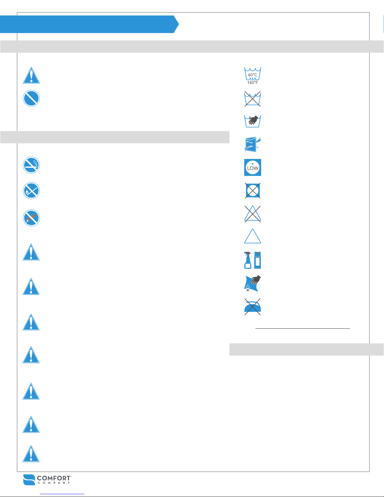
This product passed crash testing. However, when
possible, do not use head support during transport.
Repeated or excessive force (braking or crash) could
potentially change adjustment or cause extra wear
shortening the life of the product. Use after a crash is
not recommended.
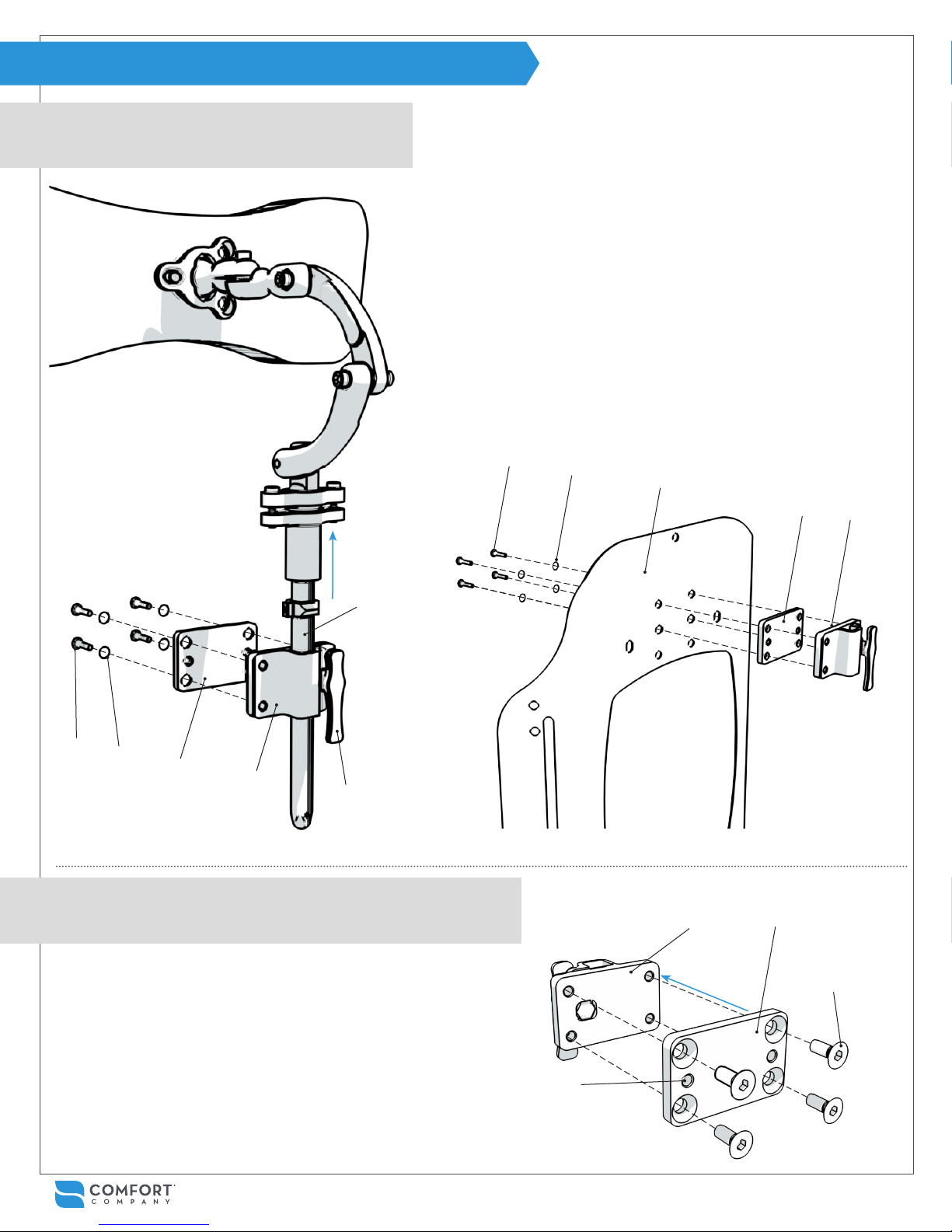
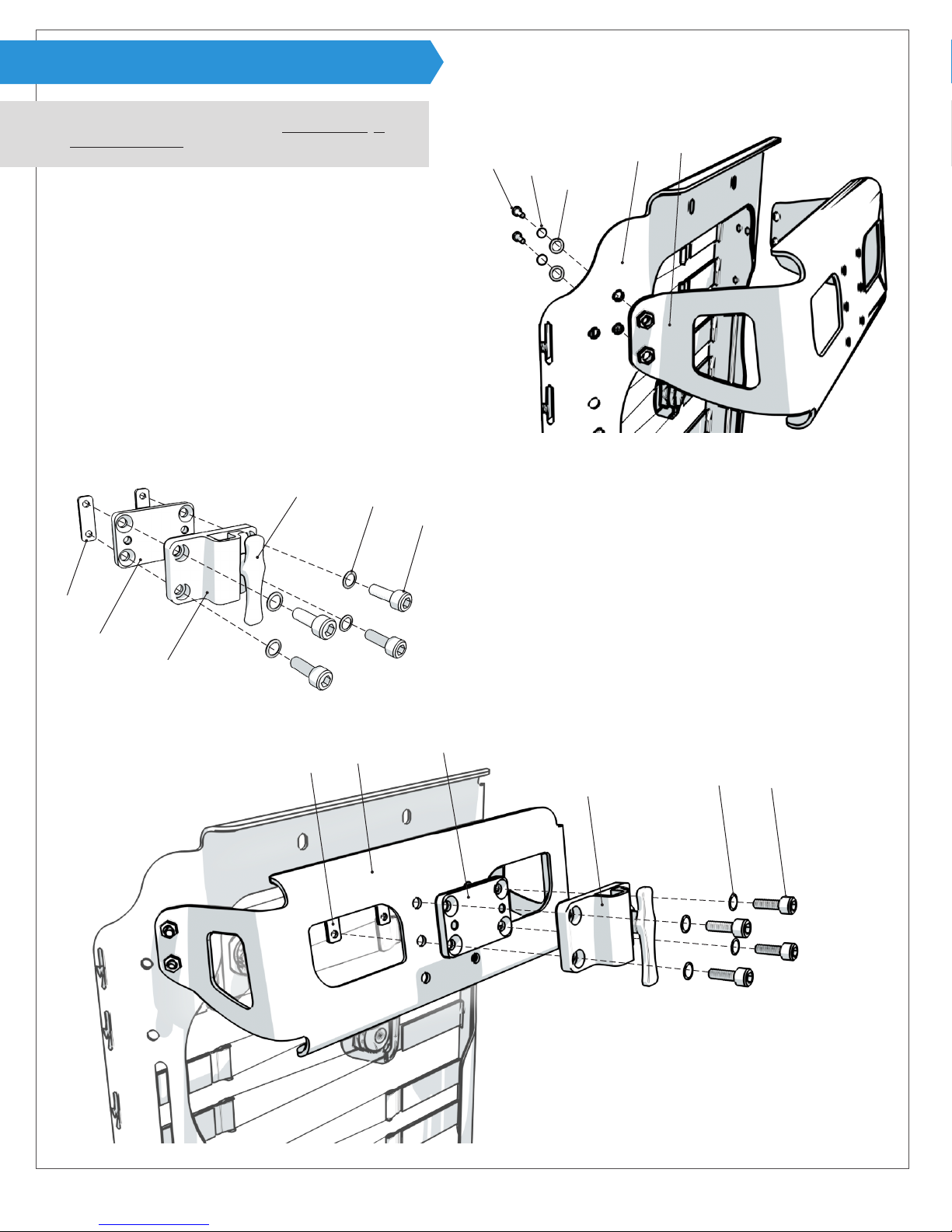
ATTENTION! Always check that the gear teeth in each joint
of are aligned for full tooth engagement before nal tight-
ening. Failing to do so could cause wear on the teeth lead-
ing to parts slipping out of adjustment or hardware failure.
(GT Hardware only)
ATTENTION! Unless otherwise specied, fasteners
should be tightened to 9.6 Nm (85 lb-in).
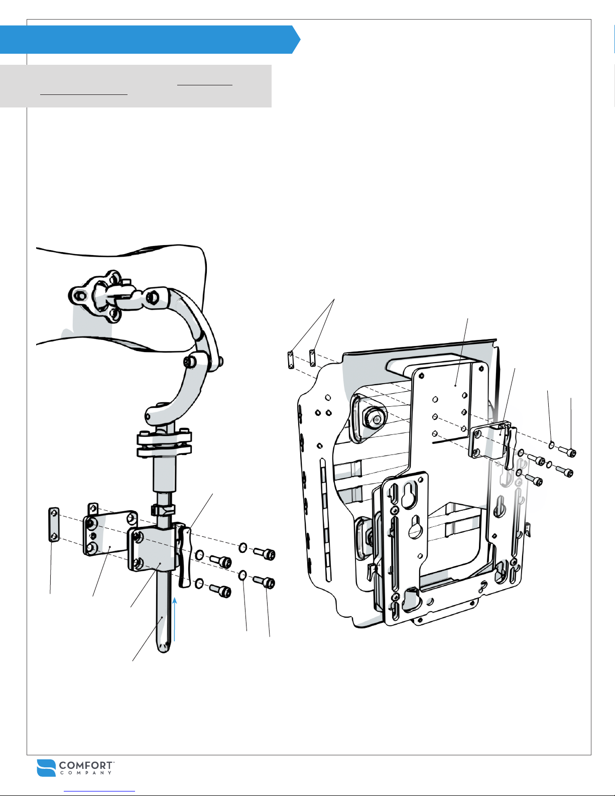
ATTENTION! Make sure that the head support is securely
mounted to the back support system and it is adjusted
properly each time it is in use.
This product is designed for the intended user and use
only. Be aware that any modications could potentially
endanger the user, cause discomfort or damage.
WARNING! It is necessary to fully articulate power recline
features to ensure there is no possible equipment interfer-
ence after installation. Do so slowly while watching closely.
Caregivers: It is necessary to learn from a healthcare provider
how to properly adjust the equipment for the user’s specic
positioning needs and goals.
WARNING! Ensure that the product does not interfere with
any other chair components. Interference could jeopardize
effectiveness and user safety as well as cause damage.
PROHIBITED! Never use the equipment to maneuver a
chair or anything that it is attached to. It is never to be
used as a handle, lift, guide or support for anything other
than what it was intended. (ex. support during transfers.)
PROHIBITED! Never use the equipment unless all compo-
nents are fully functional. Any issues should be addressed
by contacting your dealer or customer service. Do not at-
tempt to make your own modications or repairs.
SAFETY GUIDELINES
INTENDED USE - MATERIALS
BODILINKHEAD SUPPORT SAFETY DETAILS
INTENDED USER
CAUTION! Please consider that adding additional
links to the hardware may reduce the overall strength.

5
INSTALLATION & USE
PARTS DETAIL
GT Removable Hardware PT Removable Hardware - with either 7” or 3” Hardware Stem
Mounting Hardware
Additional Hardware
Support Pads
Posterior Mounting
Block
Anterior Mounting
Block
Permobil A Mounting
Block
Permobil B Mounting
Block
Quantum A Mounting
Block
¼“ Spacer Plate
Lateral Hardware Mid-6 Hardware Lat-6 HardwareMid-8 Hardware Lat-8 Hardware Max-8 Hardware
Acta-Relief™HS Mounting Bracket OnlyActa-Relief™HS Mounting Bracket
with Mounting Block
Tool-Less Wing Lock Extra 2” Link Extra 3” Link Extra 4” Link
Mid-line Hardware
BodiLinkHead Support (HS) Hardware and Pads
BodiLink®HS Basic Pads
6”W x 5”L
8”W x 5”L
10”W x 6”L
12”W x 6”L
14”W x 6”L
18”W x 6”L
BodiLink®HS Premium Pads
6”W x 3”L
8”W x 4”L
10”W x 5”L
12”W x 5”L
14”W x 5”L
18”W x 5”L
For Posterior & Anterior
Mounting Blocks
For PT Hardware Only For PT Hardware Only
Corpus Back Supports
23” - 28”H
Corpus Back Supports 20”H
For PT Hardware Only For PT Hardware Only
TRU-Comfort2Back Supports
7” Stem
3” Stem

6INSTALLATION & USE www.comfortcompany.com
INSTALLATION (POSTERIOR MOUNTING BLOCK)
For Acta-Back®, Acta-Back®Deep, Acta-Back®Contour,
Acta-Back® LTS, Acta-Embrace®, Acta-Embrace®LTS,
& Visco Back®.
For Radius Back®or other OEM Back Supports utilizing
T-nut Head Support mounting.
Rear view of Acta-Back®support shell shown
Rear view of Radius Back®support without cover shown
E
F
F
B
A
C
DG
H
E
E
B
B
DC
J
D
1If head support hardware stem is inserted in mounting block
B, turn knob Acounterclockwise to release it and set aside.
2Using 5mm hex key, loosen screws Cto release washers D,
spacer plate E, and double nuts F from mounting block B.
3Move back support cover (not pictured) allowing access from
both sides to head support holes on back support shell G.
4Align mounting block Band spacer plate Ewith desired set of
holes on back support shell G and double nuts F.
Note: Use of spacer plate Eis optional. If not using, shorter
screws are provided to replace C.
5Replace screws Cand washers Dand tighten.
6Replace and secure back support cover.
7Insert hardware stem into mounting block B and turn knob A
clockwise to secure. Note: Make sure at least ½” of hardware
stem is completely through the bottom of B at all times. See
pages 16-20 for nal adjustments.
1If head support hardware stem is inserted in mounting block
B, turn knob Acounterclockwise to release it and set aside.
2Align mounting block Band spacer plate Ewith T-nuts on
back support H.Note: Radius Back®requires creating holes
in the back support cover at the T-nut locations for attaching
mounting hardware.
3Fasten with screws Jand washers D.
4Insert hardware stem into mounting block B and turn knob A
clockwise to secure. Note: Make sure at least ½” of hardware
stem is completely through the bottom of B at all times. See
pages 16-20 for nal adjustments.

7
INSTALLATION & USE
INSTALLATION (ANTERIOR MOUNTING BLOCK)
For back supports where threading from anterior
surface of the shell is necessary or preferred.
For OEM back supports with a 2-hole head support mounting pattern.
Instructions to be used in combination with images above.
1If head support hardware stem C is inserted in mounting block B,
turn knob Acounterclockwise to release it and set aside.
2Loosen button head screws Dwith 4mm hex key and remove
along with washers Eand spacer plate Ffrom mounting block B.
3Remove back support cover (not pictured) allowing access from
both sides to head support holes on back support shell G.
4Align mounting block Band spacer plate Fwith available head
support holes on the back support shell G.
5Attach Band F with screws Dand washers Efrom the front face of
the back support shell G and tighten.
6Replace and secure back support cover.
7Insert hardware stem Cinto mounting block B and turn knob A
clockwise to secure. Note: Make sure at least ½” of stem Cis
completely through the bottom of B at all times. See pages 16-20
for nal adjustments.
1Loosen screws Dwith 4mm hex key and remove along with
washers Eand spacer plate Ffrom mounting block B.
2Use at head screws H provided with countersunk holes in
spacer plate Fto attach it to mounting block B. Make sure
the screw heads are ush with spacer plate Fwhen tightened.
3Align remaining threaded holes Jon spacer plate with holes
on the back support.
4Attach using shorter button head screws provided (not shown)
and existing washers E. See pages 16-20 for nal adjustments.
2
1
H
B
F
F
B
J
EG
D
A
B
DEF
C

8INSTALLATION & USE www.comfortcompany.com
INSTALLATION (ACTA-RELIEF™)
For Acta-Relief™& Acta-Relief™LTS using Compass®4
Mounting Hardware.
If Acta-Relief™ Head Support Bracket is already attached
to shell, please skip to step 2.
2If head support hardware stem is inserted in mounting block
B, turn knob Acounterclockwise to release it and set aside.
3Using 5mm hex key, loosen screws Cto release washers D,
spacer plate E, and double nuts F from mounting block B.
4Align mounting block Band spacer plate Ewith desired set
of holes on head support bracket H and double nuts F.
5Replace screws Cand washers Dand tighten.
6Insert hardware stem into mounting block B and turn knob A
clockwise to secure. Note: Make sure at least ½” of hardware
stem is completely through the bottom of B at all times. See
pages 16-20 for nal adjustments.
1Align holes on back support shell Gwith head support
bracket Hand attach with fasteners and hex key provided.
The bracket should be oriented with the curved edge of
the side faces at the bottom.
Assembly order:
screw J- safety washer K - at washer L- G- H
JH
KL
G
E
F
FH
BDC
E
B
A
C
D

9
INSTALLATION & USE
INSTALLATION (ACTA-RELIEF™ POWER)
For Acta-Relief™& Acta-Relief™LTS using Compass®
Power Mount Hardware.
1
H
1If head support hardware stem C is inserted in mounting block B, turn knob Acounterclockwise to release it and set aside.
2Using 5mm hex key, loosen screws Dto release washers E, spacer plate F, and double nuts G from mounting block B.
Note: Use of spacer plate Fis optional and may affect clearance in certain recline situations. If not using the spacer plate,
shorter screws are provided to replace D.
3Align mounting block Bwith desired set of head support holes on power mount bracket H and double nuts G.
4Replace screws Dand washers Eand tighten.
5Insert hardware stem C into mounting block B and turn knob Aclockwise to secure. Note: Make sure at least ½” of hard-
ware stem C is completely through the bottom of B at all times. See pages 16-20 for nal adjustments.
A
G
G
FB
C
D
D
E
E
B

10 INSTALLATION & USE www.comfortcompany.com
INSTALLATION (PERMOBIL A MOUNTING BLOCK)
For Permobil®Corpus Back Supports 23” - 28”H with
Uni-Track System using Permobil A Mounting Block.
1
3
Track Slots
1If head support hardware stem C is inserted in mounting block B, turn knob Acounterclockwise to release it and set aside.
2Using 5mm hex key, loosen but not remove screws Dto create a gap between double nuts E and mounting block B.
3Slide double nuts Einto Uni-Track System slots and move into position.
4Tighten screws D with 5mm hex key to secure.
5Insert hardware stem C into mounting bracket B and turn knob Aclockwise to secure. Note: Make sure at least ½” of stem
C is completely through the bottom of B at all times. See pages 16-20 for nal adjustments.
C
BD
D
E
B
A
E

11
INSTALLATION & USE
INSTALLATION (PERMOBIL B MOUNTING BLOCK)
For Permobil®Corpus Back Supports 20”H using
Permobil B Mounting Block.
Alternate options when using Permobil B Mounting Block.
Standard and Alternate Mounting Block Placement on Mounting Bracket
Accessory Rail attached to Mounting Bracket
Countersunk Holes
1If head support hardware stem is inserted in mounting block B, turn knob Acounterclockwise to release it and set aside.
2Using 5mm hex key, loosen screws Cto release washers D, and double nuts F from mounting bracket E.
3Move back support cover (not pictured) allowing access from both sides to head support holes on back support shell G.
4Align mounting bracket Ewith head support holes on back support shell G and double nuts F.
5Replace screws Cand washers Dand tighten.
6Replace and secure back support cover.
7Insert hardware stem into mounting block B and turn knob Aclockwise to secure. Note: Make sure at least ½” of
hardware stem is completely through the bottom of B at all times. See pages 16-20 for nal adjustments.
1Remove screws Gand washers Hon mounting block B.
2Align mounting block Bwith alternate holes on
mounting bracket E.
3Replace screws Gand washers Hand tighten.
F
F
E
G
E
B
HG
D
DC
C
BE
A
Note: Additional Corpus Seating System accessory rail can
be attached to the inner face of mounting bracket if needed
using the countersunk holes on the mounting bracket. Access
countersunk holes using instructions to the left. Please refer
to accessory rail instructions for proper attachment and use.

12 INSTALLATION & USE www.comfortcompany.com
INSTALLATION (QUANTUM MOUNTING)
For Quantum®TRU-Comfort2Back Supports on TRU-Balance3
Seating System using Quantum Mounting Block.
G
B
B A
C
D
Note: This process can not be completed if mounting bracket Cis already mounted to the back support.
Remove screws E(pictured above) prior to step 1if needed.
1If head support hardware stem is inserted in mounting block B, turn knob Acounterclockwise to release it and set aside.
2Attach mounting plate Cto back support G with socket head screws Eand tighten using 4mm allen wrench.
3Insert hardware stem into mounting bracket B and turn knob Aclockwise to secure.
Note: Make sure at least ½” of stem is completely through the bottom of B at all times. See pages 16-20 for nal adjust-
ments.
E
C
Alternate option when using Quantum Mounting Block.
Instructions to be used in combination with images above.
Alternate Mounting Block Placement on Mounting Bracket
1Remove at head screws Don mounting plate Cusing phillips head screwdriver.
2Align mounting block Band alternate countersunk holes of mounting plate C and attach with at head screws D.
Make sure the screw heads are ush with mounting plate Cwhen tightened.

13
INSTALLATION & USE
INSTALLATION (ADDING A LINK TO GT HARDWARE)
BodiLink®Head Support GT Lateral Hardware will
include an extra link and fasteners to use if needed
to reach extreme positions.
CAUTION! Please consider that adding additional
links to the hardware may reduce the overall strength.
1Remove screw D and safety washer E from curved link F and top of hardware stem C.
2Remove hardware stem Cfrom mounting bracket Bby turning knob Acounterclockwise.
3Turn hardware stem C180° so the visible gear teeth are facing the opposite direction.
4Insert hardware stem Cinto mounting bracket B and turn knob Aclockwise to secure.
Note: Make sure at least ½” of stem Cis completely through the bottom of Bat all times.
1
42
3
C
A
C
E
F
D
5Align extra link G with gear teeth on hardware
stem C in the orientation shown below and fasten
with safety washer H and screw J.
6Align the other end of extra link G with curved link
F and fasten with safety washer E and screw D.
7See pages 16-20 for information on nal
adjustments.
Proper gear tooth alignment and engagement is
essential for a secure set up.
5
6
C
E
J
F
G
D
H
B
Gear Tooth Alignment

14 INSTALLATION & USE www.comfortcompany.com
INSTALLATION (ADDING A LINK TO PT HARDWARE)
BodiLink®PT Hardware Extra 2”, 3”, and 4” Links.
Taper inserts may be oriented so screws face either left or right.
1Remove screw A and safety washer B from taper insert C. Separate link D and ball link E.
2Align new link F with link D.
3Place existing taper insert C halves (countersunk side rst) in end of link Dmaking sure the square
ends are aligned inside for a low-prole t in the joint. Countersunk side of all taper inserts C
should consistently face the same direction on hardware so that screws Aare all on the same side.
4Insert screw A and safety washer B into countersunk side of taper insert Cand tighten. Hold the
threaded side of taper insert C rmly while fastening.
5Align new link F joint with ball link E.
6Place new taper insert G halves (countersunk side rst) in the end of ball link Emaking sure the
square ends are aligned inside for a low-prole t in the joint.
7Insert screw H and safety washer J into countersunk side of taper insert Gand tighten. Hold the
threaded side of taper insert rmly while fastening.
F
DD
F
A
A
A
BB
B
CC
C
E
E
E

15
INSTALLATION & USE
INSTALLATION (TOOL-LESS WING LOCK)
BodiLink®PT Hardware Tool-Less Wing Lock.
Taper inserts may be oriented so screws and wing locks face either left or right.
1Remove screw A and safety washer B from taper insert C in the joint you will be replacing with a wing lock.
2Remove threaded half of taper insert Cand replace with threaded end from wing lock Dmaking sure the squares of D
and the remaining countersunk half of C are aligned inside for a low-prole t in the joint.
3Insert wing lock E and safety washer F into taper lock Chalf and tighten. Hold the taper lock D rmly while fastening.
4Align retainer clip G with tip of wing lock E and press on hard. The convex side of the retainer clip must face out.
Note: the retainer clip is very difcult to remove once installed. Adding it to the wing lock assembly should be
considered a permanent change.
5Repeat steps 1through 4 for each joint being replaced with a wing lock.
A
E
E
B
F
D
D
G
Threaded End
C Countersunk End
C

16 INSTALLATION & USE www.comfortcompany.com
Instructions apply to both Basic and Premium pads with
any style of hardware.
Final pad positioning should be completed in conjunction with hardware adjustments detailed on following pages. Premium BodiLink®Head Support
pads have a preformed curvature for optimal posterior contact, and 10 - 18” W pads have 2 points of adjustment for additional lateral support.
INSTALLATION (SUPPORT PAD)
SET UP & ADJUSTMENTS (PADS)
1
1Align ball link Aand ball ring B with ball receiver C.
2Loosely engage screws Dand safety washers E
with ball receiver C to complete the assembly.
3Continue through page 20 for nal adjustments.
A
B
C
D
C
180°
A
B
E
8W x 4L Premium Pad and GT Hardware Shown
2
14W x 5L Premium Pad Without Cover
and GT Hardware Shown
Gear Tooth Alignment
1Loosen all hardware adjustment point screws allowing
for full articulation of the head support to a desired
position. Loose screws A around ring B will allow pad
orientation adjustment.
Note: Premium BodiLink®head support pads are de-
signed to be used in any orientation including ipped
180º as shown.
2PREMIUM PADS: To access wing adjustment screws C
on 10” - 18”W pads, partially unzip the locking zippers
under the cover aps. Screw heads are accessible in
the channels. Ensure gear teeth are properly aligned
before nal tightening.
3BASIC PADS: Mold pad by bending with hands or over
a rm surface. Basic pads not pictured.
ATTENTION: If screws Aare are not evenly
tightened all around ring B, unwanted movement
may occur. Additionally, the gear teeth on
premium wing adjustments must be properly
aligned and engaged for a secure setup.

17
SET UP & ADJUSTMENTS
SET UP & ADJUSTMENTS (HARDWARE)
All BodiLink®Head Support hardware styles have adjustment for height* and depth to be used in combination with pad positioning described on
previous page. Some hardware styles also have lateral positioning features. For GT Hardware, see page 18. For PT hardware, see page 19.
*Amount of height adjustment available is dependent on the stem length ordered
GT Hardware
Mid-line Positioning Only
Mid-6 Lat-6Mid-8 Lat-8 Max-8
Mid-line Positioning Only
Lateral Positioning Available Lateral Positioning Available
PT Hardware
Lateral GT Hardware with Additional Link Shown Max 8 PT Hardware with 7” Stem Shown

18 SET UP & ADJUSTMENTS www.comfortcompany.com
SET UP & ADJUSTMENTS (GT HARDWARE)
Lateral Style GT Hardware (without additional link added) shown. Mid-line GT hardware will not have angle adjustment points.
Adjustments to be made simultaneously with pad positioning adjustments.
A
H
D
A = Angle/Lateral Offset
D = Depth
H = Height
1Loosen all hardware adjustment point screws
allowing for full articulation of the head support
to a desired position.
2Hold hardware and pad in place while tightening each
joint. Note that adjustments may be affected by each
other as gear teeth engage and require compensation
from other joints before nal tightening.
ATTENTION: It is crucial that gear teeth in all joints are
properly aligned and engaged for a secure set up.
14W x 5L pad shown
D
A
Gear Tooth Alignment

19
SET UP & ADJUSTMENTS
SET UP & ADJUSTMENTSSET UP & ADJUSTMENTS (PT HARDWARE)
Max-8 Style PT Hardware (with 7” stem) shown. Other PT hardware styles will not have angle or as many depth adjustment points.
Adjustments to be made simultaneously with pad positioning adjustments.
A = Angle/Lateral Offset
D = Depth
H = Height
Standard
Taper Inserts
Tool-Less
Wing Locks
(not pictured)
A
D
D
H
1Loosen all hardware adjustment point screws allowing for full
articulation of the head support to a desired position.
2Hold hardware and pad in place while tightening each joint.
1Turn wing lock(s) counter-clockwise to loosen hardware
adjustment points allowing for articulation.
2Turn wing lock(s) clockwise to tighten.

20 SET UP & ADJUSTMENTS www.comfortcompany.com
Locking the height adjustment collar on GT and PT hardware.
3” Stem does not have a height adjustment collar.
FINISH
A
C
A
E
C
D
B
GT Hardware Shown
1Finish setup by loosening set screw Din collar A.
2Slide collar A on hardware stem C to meet the top of mounting bracket B.
3Tighten set screw Din the collar with 2mm hex key until contact is made with the hardware stem.
This allows for easy positioning of the hardware if it is removed and then replaced.
Note: Collar Ais retained in a track in stem C. If the collar needs to be removed, remove the set
screw Elocated in the track at the bottom of the stem with the 2mm allen wrench provided.
This manual suits for next models
24
Table of contents
Popular Mobility Aid manuals by other brands

Life & Mobility
Life & Mobility PRESTO user manual

Drive DeVilbiss Healthcare
Drive DeVilbiss Healthcare 10306AT-6 instruction manual

Antar
Antar AT51039 user manual

Aqua Creek Products
Aqua Creek Products Mighty 400 manual

Anatomic SITT
Anatomic SITT Zitzi Pengy user manual

aidapt
aidapt VP129F Fixing and maintenance instructions