2
104079
Wire
Harness
1
2
Bottom Louver
Assembly
Remove
Screw Valve
Cover
Shield
Shoulder
Screw
Installing Blower Assembly
Note:
If you are using a mantel with your heater, use the following instructions. If your heater is built-in, see For
Built-In Installation on page 3.
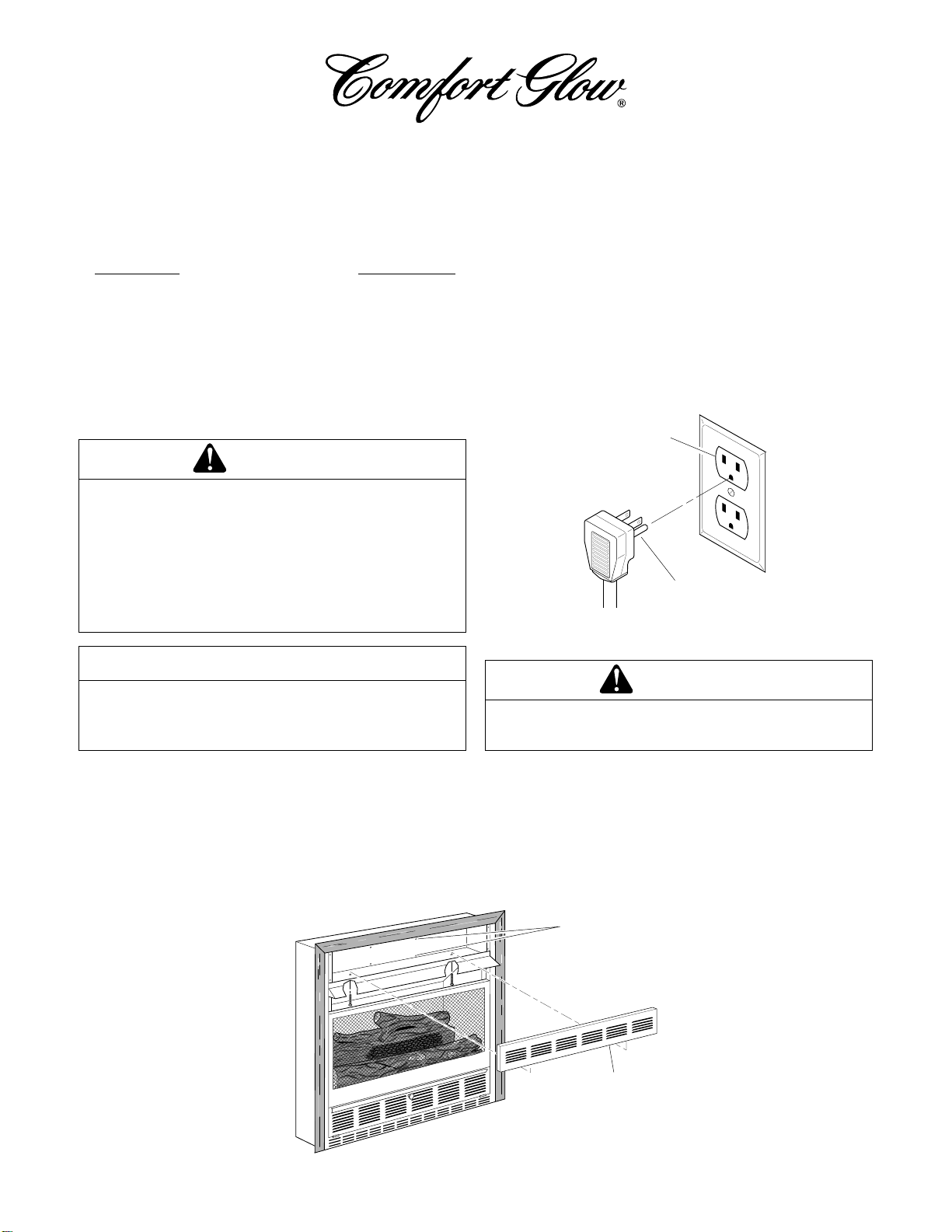
Standard Installation
Removing Valve Cover Shield
1. Open bottom louver assembly by swinging
the assembly down (see Figure 3).
2. Using short Phillips screwdriver, remove the
screw under the center of the branch support.
Rotatevalvecovershieldclockwiseandslide
out.
IMPORTANT :
Do not remove shoulder
screw on the left side of valve cover shield.
Slide the valve cover shield off of the shoul-
der screw (see Figure 3).
Note:
If you do not have a short Phillips
screwdriver, the screen, twigs, and branch
support must be removed so a longer
screwdriver may be used. Follow directions
in the owner’s manual for screen and twig
removal/installation. Branch support may
be removed by removing 2 screws on each
side of the support.
Figure 3 - Removing Valve Cover Shield
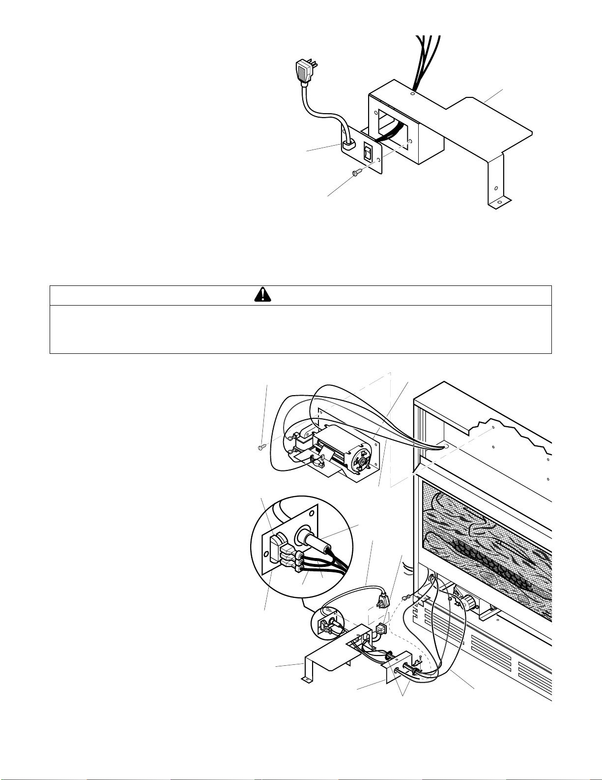
Figure 4 - Installing Blower Bracket Assembly
1. Install snap bushings found in hardware kit
into both holes in rear of valve cover shield.
2. Make sure the wire harness is firmly
connected to the terminals on the blower
bracket assembly.
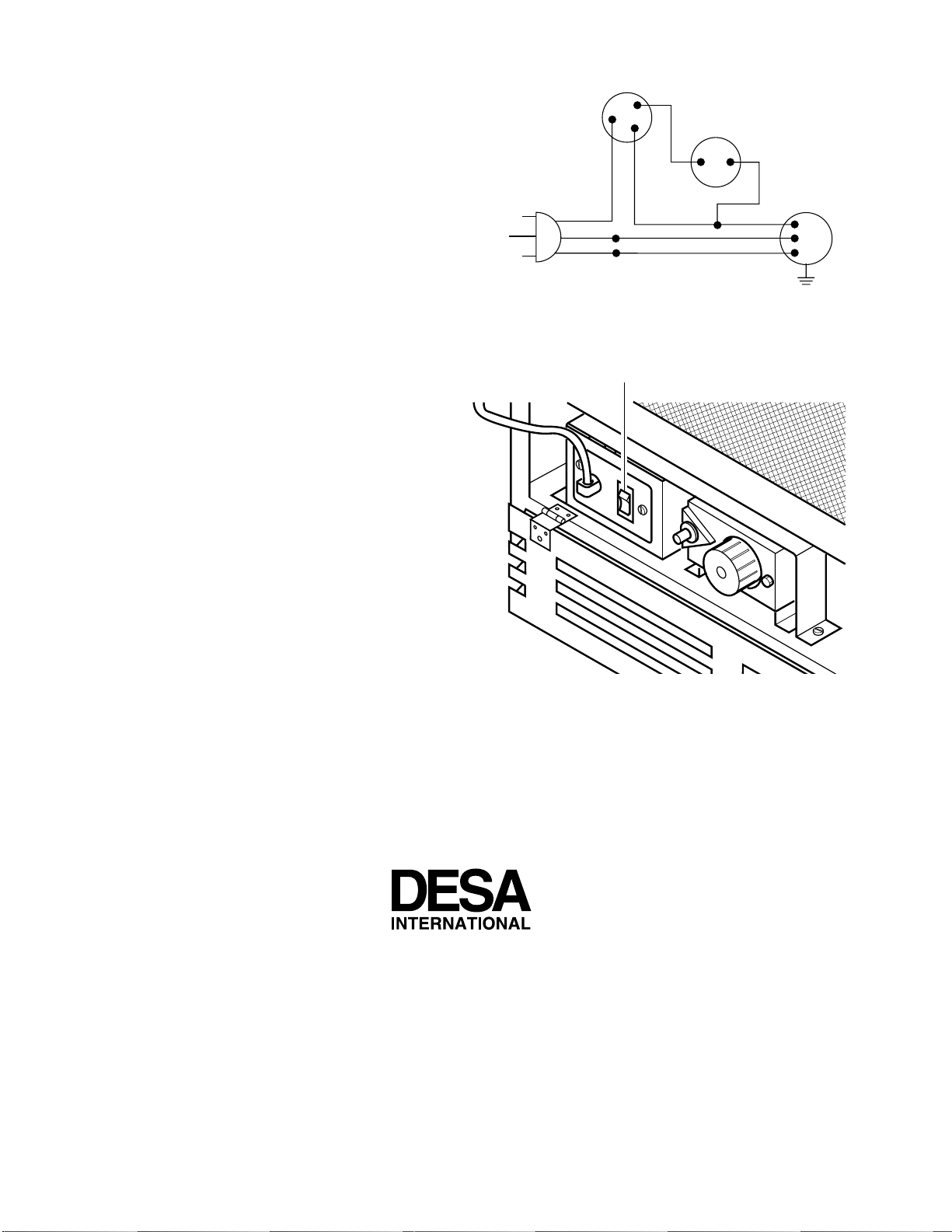
3. Note the wire locations on back of AUTO/
OFF/ON switch. The terminals on back of
switch are numbered 1, 2, and 3. Carefully
remove red wire from terminal 1 and blue
wire from terminal 3. Black wire can
remain on middle terminal 2 (see figure 4).
4. Carefully disconnect green and white wires
at their insulated connectors.
5. In top of the heater cabinet, locate the four
mounting holes on the outer casing. Align
these four holes with those on the blower
bracket assembly. Attach blower bracket
assembly to the outer casing with 4 #10
screws provided (see Figure 4).
6. Route the wire harness through the hole in
left side of baffle. Pull wire harness through
lower opening above where the valve shield
was removed. (see Figure 4).
7. Insert the 4 wire harness into one of the
round holes in the rear of the valve cover
shield and through the rectangular hole in
the front of shield (see figure 4).
8. Reconnect red wire to switch position 3.
Reconnect blue wire to switch position 1.
Reconnect green and white wires.
Blower Bracket
Assembly
Screw
Power
Cord
Valve
Cover
Shield Box Cover
Wire
Harness
Switch
Plate
Switch
Baffle
Branch Support
Wiring Routing
Hole in Baffle
Snap
Bushings
3
2
1
Blue Red