MS-C71 User’s Manual
-7-
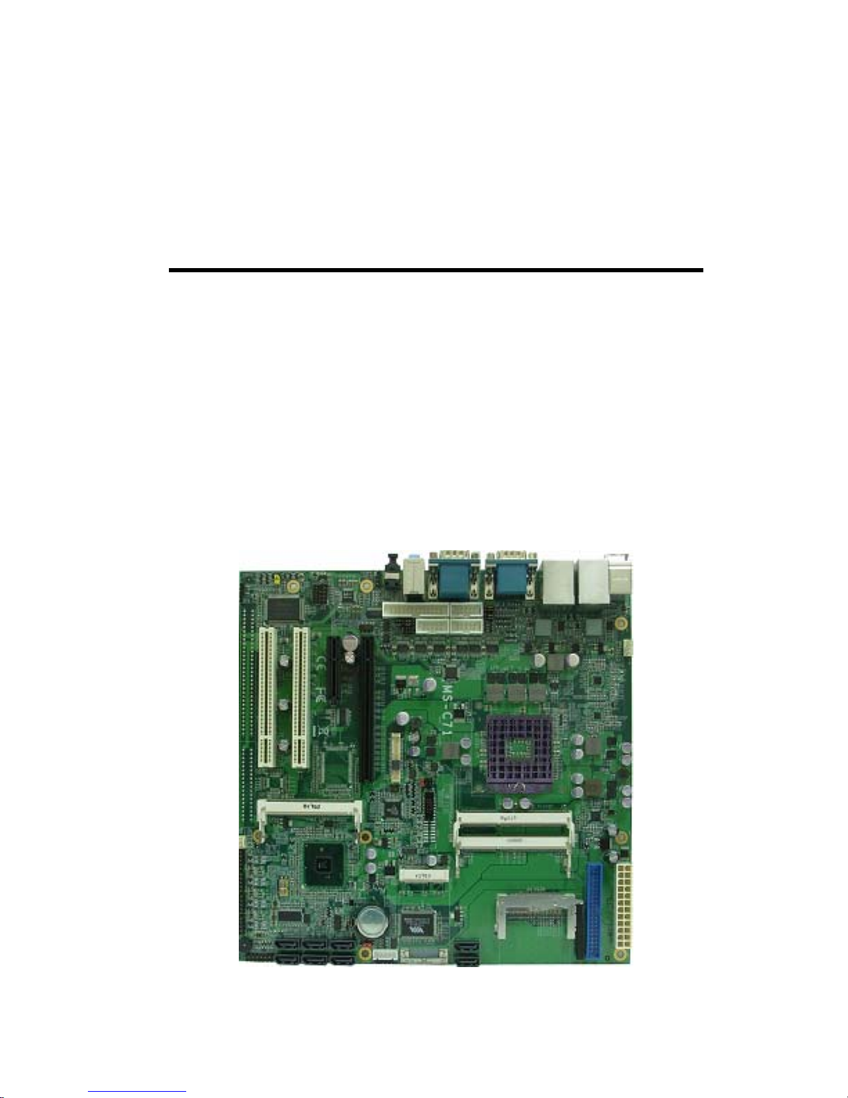
1.2 <Product Specification>
General Specification
Form Factor Micro ATX motherboard
CPU Intel® Core™ i7 / i5 / i3 / Celeron® / Pentium® Mobile Processor
Package type: rPGA988A
Memory 2 x DDRIII SO-DIMM 800/1066 MHz up to 8GB
Chipset Intel QM57
Real Time Clock Chipset integrated RTC with onboard lithium battery
Watchdog Timer Generates a system reset with internal timer for 1min/s ~255min/s
Power Management Supports ACPI 2.0 compliant,
Serial ATA Interface 6 x serial ATAII interface with 300MB/s transfer rate
2 x serial ATAI interface with 150MB/s transfer rate
IDE UltraATA133 IDE interface supports up to 2 ATAPI devices
One 40-pin IDE port onboard with VT-6421
VGA Interface Intel integrated HD Graphic Technology
LVDS interface Onboard 24-bit dual channel LVDS connector
with +3.3V/+5V/+12V supply
Audio Interface Realtek ALC888 HD Audio
LAN Interface 2 x Intel 82574L Gigabit LAN
GPIO interface Onboard programmable 8-bit Digital I/O interface
Extended Interface 1 x PCIE x16 slot, 1 x PCIE x 4 slot, 1 x Mini PCIE socket, 2 x PCI Slot
1 x Mini PCI socket to support Mini PCI Type IIIA
Internal I/O Port 3 x RS232, 1 x SMBUS, 1 x GPIO port, 8 x USB ports, 1 x IrDA,
8 x Serial ATA, 1x LVDS, 1x LCD inverter connector, 1 x CF
1 x Audio connector and 1 x CDIN connector
External I/O Port 1 x PS/2 Keyboard/Mouse Port, 2 x RJ45 LAN ports, 1 x DB15 VGA port,
4 x USB2.0 ports, 1x RS232/422/485 port, 2 x RS232 port
2 Channel Audio, 1 x SPDIF connector
Power Requirement Standard 24-Pin ATX power
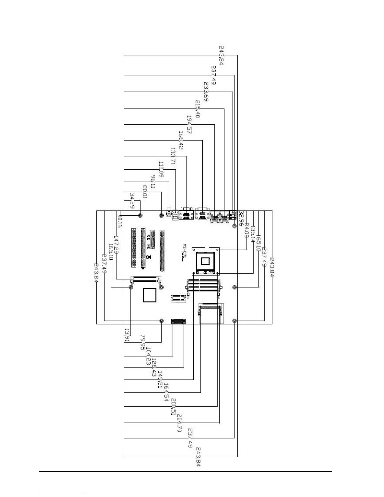
Dimension 244mm x 244mm
Temperature Operating within 0~60 centigrade
Storage within –20~85 centigrade
Ordering Code
MS-C71 Intel Arrandale + QM57 Onboard VGA, LVDS, LAN, USB2.0, HD Audio,
SATA, SMBUS, PCIE x16, PCIE x4, PCI , Mini PCI and PCIE mini card
MS-C71XD Same as MS-C71X with 1x DVI Interface
MS-C71XT Same as MS-C71X with secondary CRT
MPX-7202 PCI Express mini card supports
2 x USB 3.0 provides up to 4.8Gbps of transferring rate.
The specifications may be different as the actual production.
For further product information please visit the website at TUhttp://www.commell.com.twUT