Commell LV-678 User manual

LV-678
Mini-ITX motherboard
User’s Manual
Edition: 1.00
2008/06/13

LV-678 User’s Manual
2
Copyright
Copyright 2008. All rights reserved. This document is copyrighted and all rights are
reserved. The information in this document is subject to change without prior notice to make
improvements to the products.
This document contains proprietary information and protected by copyright. No part of this
document may be reproduced, copied, or translated in any form or any means without prior
written permission of the manufacturer.
All trademarks and/or registered trademarks contains in this document are property of their
respective owners. Disclaimer
The company shall not be liable for any incidental or consequential damages resulting from
the performance or use of this product.
The company does not issue a warranty of any kind, express or implied, including without
limitation implied warranties of merchantability or fitness for a particular purpose.
The company has the right to revise the manual or include changes in the specifications of
the product described within it at any time without notice and without obligation to notify any
person of such revision or changes.
Trademark
All trademarks are the property of their respective holders.
Any questions please visit our website at TUhttp://www.commell.com.twUT.

LV-678 User’s Manual
3
Packing List
Please check package component before you use our products.
Hardware:
LV-678 Mini-ITX motherboard x 1
Cable Kit:
Other Accessories:
Divers CD (including User’s Manual) x 1
RAID drivers Disc for Windows 2000,
Windows XP and Windows Server 2003
SATA Cable x 2
26-pin Slim Type Floppy Cable x 1
I/O Shield x 1
SATA Power Y Cable x 1
USB Cable x 1 COM Port Cable x 1

LV-678 User’s Manual
4
Index
Chapter1 <Introduction>............................................................7
1.1 <Product Overview> .............................................................................................7
1.2 <Product Specification> ........................................................................................8
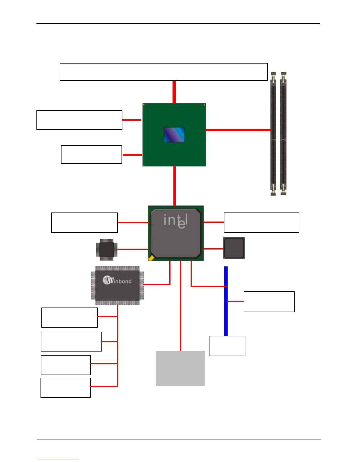
1.3 <Block Diagram> ................................................................................................10
1.4 <Mechanical Drawing > ......................................................................................11
Chapter 2 <Hardware Setup>.................................................13
2.1 <Connector Location>.........................................................................................13
2.2 <Jumper Reference>..........................................................................................14
2.3 <Connector Reference>......................................................................................15
2.3.1 <Internal Connectors> ..............................................................15
2.3.2 <External Connectors> .............................................................15
2.4 <CPU and Memory Setup>.................................................................................16
2.4.1 <CPU installation>...................................................................16
2.4.2 <Memory installation>..............................................................17
2.5 <CMOS Setup>...................................................................................................18
2.6 <Serial ATA installation>......................................................................................19
2.7 <Floppy Installation>...........................................................................................20
2.8 <LAN installation>...............................................................................................21
2.9 <Onboard Display Interface>..............................................................................22
2.9.1 <Analog Display>....................................................................22
2.10 <Audio Installation> ..........................................................................................23
2.11 <GPIO interface> ..............................................................................................25
2.12 < USB Installation> ...........................................................................................26
2.13 <Power and Fan Installation> ...........................................................................28
2.14 <Serial Port>.....................................................................................................30
2.15 <Switch and Indicator> .....................................................................................31
Chapter 3 <System Configuration>.......................................33

LV-678 User’s Manual
5
3.1 <SATA configuration>..........................................................................................33
3.2 <SATA RAID Configuration> ...............................................................................34
3.3 <Audio Configuration> ........................................................................................38
3.4 <Video Memory Setup> ......................................................................................39
Chapter 4 <BIOS Setup>.........................................................41
Appendix A <I/O Port Pin Assignment>................................43
A.1 <Serial ATA Port>................................................................................................43
A.2<Floppy Port>......................................................................................................43
A.3 <IrDA Port>.........................................................................................................44
A.5 <VGA Port> ........................................................................................................44
A.6 <LAN Port>.........................................................................................................45
Appedix B <System Resources>...........................................46
Appedix C <Flash BIOS>.........................................................50
C.1 BIOS Auto Flash Tool..............................................................................50
C.2 Flash Method ...........................................................................................50
Appendix D <Programming GPIO’s>....................................51
Appendix E <Watch Dog timer Setting >..............................52
Contact Information...................................................................53

LV-678 User’s Manual
6
(This Page is Left for Blank)

LV-678 User’s Manual
7
Chapter1 <Introduction>
1.1 <Product Overview>
LV-678 is the motherboard with last Intel desktop technology with Mini-ITX form factor.
Based on Intel®Q35 and ICH9DO, the board integrates a new Core2 Quad / Core 2 Duo
processor 775-pin socket, DDR2 memory socket, Intel®Graphic Media Accelerator 3100
technology, Serial ATA II with RAID function for a powerful desktop system.
Intel®LGA775 processor
The Intel®Core2 Quad / Core 2 Duo processor now comes with a new form factor with
775-pin PLGA package, for 800/1066/1333MHz front-side-bus, 8MB L2 cache, for 65nm
and 45nm manufacturing technology, the PLGA processor without pin header on solder side
can make user installing the processor on the socket easier.
Intel®Q35 and ICH9DO chipset
The Intel Q35 integrates DDR2 667/800MHz for memory, and Graphic Media Accelerator
(GMA) 3100 technology for new graphic engine. It can provide up to 384MB of frame buffer
when you install over 1GB of system memory. The ICH9DO integrates with up to 6 USB2.0
interfaces and serial ATA II interface with RAID function.
Flexible Extension Interface
LV-678 provides one PCIE slot for X16 graphics card, it also can support
PCI Express X1 device and one Mini-PCI socket.

LV-678 User’s Manual
8
1.2 <Product Specification>
General Specification
Form Factor Mini-ITX motherboard
CPU Support Intel Core 2 Quad / Core 2 Duo / Celeron processor
Package type: LGA775
Front side bus: 800 / 1066 / 1333MHz
Memory Two DDRII 667 / 800 MHz DIMM up to 4GB
Chipset Intel Q35 & ICH9DO
Real Time Clock Chipset integrated RTC with onboard lithium battery
Watchdog Timer Generates a system reset with internal timer for 0 ~255min/s
Power Management ACPI 1.0 compliant, supports power saving mode
Serial ATA Interface Intel ICH9DO built-in 6 x Serial ATAII interface up to 300MB/s
Support RAID 0,1,5,10 and Intel Matrix Storage Technology
VGA Interface Intel integrated extreme GMA 3100 (Graphic Media Accelerator)
Technology
Video Memory Up to 384MB shared with system memory
A
udio Interface Intel integrated ICH9DO with Realtek ALC888 HD Audio
LAN Interface 2 x Intel 82573L Gigabit LAN
GPIO interface Onboard programmable 8-bit Digital I/O interface
Extended Interface One PCIE x 16 slot, one Mini-PCI Type III A
Internal I/O Port 1 x RS232/422/485, 1 x slim FDD port, 1 x GPIO port, 1 x CDIN
connector, 1 x Audio connector, 1 x IrDA connector and 2 x USB
ports
External I/O Port 2 x RJ45 LAN ports, 1 x DB15 VGA port, 1 x PS/2
Keyboard/Mouse Port, 6 x USB2.0 ports, 1 x SPDIF connector
and 1 x Serial Port
External Audio Line-in, MIC-in, Front, Rear, Center/Subwoofer and Side outputs
Power Requirement Standard 24-pin ATX power supply and P4 4-pin 12V (20-pin is
compatible)
Dimension 170mm x 170mm
Temperature Operating within 0~60 centigrade
Storage within -20~85 centigrade
Multi-I/O Port
Chipset Intel Q35, ICH9DO (82801IO) & 8M SPI
Serial Port One external RS-232 and one internal RS232/422/485 serial ports
USB Port Eight Hi-Speed USB 2.0 ports with 480Mbps of transfer rate
Floppy Port One slim type Floppy port
IrDA Port One IrDA compliant Infrared interface supports SIR
K/B & Mouse External PS/2 keyboard and mouse ports on rear I/O panel
GPIO One 12-pin Digital I/O connector with 8-bit programmable I/O
interface
Smart Fan One CPU fan connectors for fan speed controllable

LV-678 User’s Manual
9
VGA Display Interface
Chipset Intel Q35, ICH9DO
Frame Buffer Up to 384MB shared with system memory
Display Type CRT or LCD monitor display
Ethernet Interface
Controller Two Intel 82573L Gigabit Ethernet controller
Type Triple speed 10/100/1000Base-T
Auto-switching Fast Ethernet
Full duplex, IEEE802.3U compliant
Connector Two External RJ45 connectors with LED on rear I/O panel
Audio Interface
Chipset Intel Q35, ICH9DO (82801IO) & 8M SPI
Intel High Definition Audio compliance
Interface 7.1 channels sound output
Connector External six phone jack for 7.1 channel audio on rear I/O panel
External SPDIF connector on rear I/O panel
Internal 10-pin header for line-in/-out, MIC-in, 4-pin header for CD-IN
Expansive Interface
Mini PCI One Mini-PCI socket TYPE III A (32-bit, 33MHz)
Power supply: +3.3V, +5V
Power and Environment
Power
Requirement Standard ATX 24-pin (20-pin is compatible) power supply
Additional +12V 4-pin power connector
Dimension 170 (L) mm x 170 (H) mm
Temperature Operating within 0 ~ 60P
o
PC (32 ~ 140P
o
PF)
Storage within -20 ~ 85P
o
PC (-4 ~ 185P
o
PF)
Ordering Code
LV-678 Onboard VGA, 2 x Intel Gigabit LAN, 6 x USB2.0, Mini-PCI, 2 x serial Port,
1 x slim FDD Realtek ALC888 HD 7.1 Channel Audio, 6 x SATA, 1 x IrDA
MP-6421 Mini PCI with one 44-pin Ultra DMA 33 IDE interface supports up to 2
ATAPI devices
1 x Compact Flash Type II and 2 x serial ATA interface
The specifications may be different as the actual production.
For further product information please visit the website at TUhttp://www.commell.com.twUT

LV-678 User’s Manual
10
1.3 <Block Diagram>
Intel Core 2 Quad / Core 2 Duo Celeron with 775
p
in PLGA
Intel Q35 2 x 240-pin DDR2
667/800MHz up to
4GB
PCI bus
Mini-PCI slot
2 x Serial ports
1 x Slim Floppy
8-bit GPIO
8 x USB2.0 ports
HD Audio ICH9DO
6 x Serial ATAII ports
Intel 82573L
2 x GLAN
IrDA
BIOS
SPI
Intel GMA3100 Graphics
PCI-Express x16

LV-678 User’s Manual
11
1.4 <Mechanical Drawing >
‘
‘
‘
‘
‘
‘
‘
‘
‘
‘
‘‘‘‘
‘
‘
‘‘
‘

LV-678 User’s Manual
12

LV-678 User’s Manual
13
PS2
Chapter 2 <Hardware Setup>
2.1 <Connector Location>
CN_12
V
CN_USB
CPUFAN
JAT
SYSFAN
JFRNT
JRTC
CN_AUDIO
SPDIF
CN_I
R
FDD
CRT
RJ45_1/2
USB Audio
CN_DIO
S_ATA1~6
PCIE_16X
Mini-PCI
A
T
X
CN_COM2
JCSEL1
JCSEL2
DDRII 1/2
COM1
CDIN

LV-678 User’s Manual
Connector Reference14
JAT
2.2 <Jumper Reference>
Jumper Function
JRTC CMOS Operating/Clear Setting
JAT Power mode select
Power Mode JAT
AT Mode
ATX Mode
Default setting: ATX Mode
JRTC
1
3
1
3
1
3

LV-678 User’s Manual
15
2.3 <Connector Reference>
2.3.1 <Internal Connectors>
Connector Function Remark
CPU LGA775 CPU socket
DDRII1/2 240 -pin DDR2 SDRAM DIMM socket
Slim FDD 26-pin slim type floppy connector
S_ATAII1/2/3/4/5/6 7-pin Serial ATA II connector
ATX 24-pin power supply connector
CN_12V 4-pin +12V additional power supply connector
CN_AUDIO 5 x 2-pin audio connector
CDIN 4-pin CD-ROM audio input connector
CN_DIO 6 x 2-pin digital I/O connector
CN_USB 10-pin USB connector
CPUFAN 4-pin CPU cooler fan connector
SYSFAN 3-pin system cooler fan connector
CN_IR 5-pin IrDA connector
JFRNT 14-pin front panel switch/indicator connector
PCIE_16X 1 PCI Express 16x slot
Mini-PCI 1 x Mini-PCI socket
CN_COM2 5 x 2-pin com connector
2.3.2 <External Connectors>
Connector Function Remark
PS2 PS/2 Keyboard/Mouse connector
CRT+COM1 DB15 VGA + Serial port connector
USB_RJ45_1/2 Dual USB and one RJ45 LAN Port
AUDIO Audio connectors
SPDIF SPDIF digital audio output connector

LV-678 User’s Manual
16
2.4 <CPU and Memory Setup>
2.4.1 <CPU installation>
LV-678 has a LGA775 CPU socket onboard; please check following steps to install the
processor properly.
Attention If LV-678 need RMA please Keep CPU socket cover on the CPU Socket.
Warning Warranty void if CPU socket internal pin damage.
Intel®Core2 Quad/Core 2 Duo/Celeron processor
Package type: 775 pin LGA
L2 Cache: 4 MB
FSB: 800/1066/1333MHz (266MHz x 4)
Manufacturing: 65nm and 45nm
1. Lift this bar
2. Uncover this plate
Check point
3. Place the CPU on the top o
f
the
p
ins
3. Cover this plate
4. Lock this bar
Notice: Please place the CPU on the pins tenderl
y
to avoid bendin
g
the pins

LV-678 User’s Manual
17
2.4.2 <Memory installation>
LV-678 has two 240-pin DDR2 DIMM support up to 4GB of memory capacity. The memory
frequency supports 667/800MHz. Only Non-ECC memory is supported.
DDRII1/2
112-pin128-pin
Please check the pin number to match the socket side well
before installing memory module.

LV-678 User’s Manual
18
2.5 <CMOS Setup>
The board’s data of CMOS can be setting in BIOS. If the board refuses to boot due to
inappropriate CMOS settings, here is how to proceed to clear (reset) the CMOS to its
default values.
Jumper: JRTC
Type: Onboard 3-pin jumper
JRTC Mode
1-2 Clear CMOS
2-3 Normal Operation
Default setting 2-3
JRTC
1
3

LV-678 User’s Manual
19
2.6 <Serial ATA installation>
LV-678 has six Serial ATA II interfaces with RAID function, the transfer rate of the Serial ATA
II can be up to 300MB/s. Please go to http://www.serialata.org/ for more about Serial ATA
technology information. Based on Intel®ICH9DO, it supports Intel®Matrix Storage
Technology with combination of RAID 0,1,5 and 10. The main features of RAID on
ICH8DO are listed below:
1. Supports for up to RAID volumes on a single, two-hard drive RAID array.
2. Supports for two, two-hard drive RAID arrays on any of six Serial ATA ports.
3. Supports for Serial ATAATAPI devices.
4. Supports for RAID spares and automatic rebuild.
5. Supports on RAID arrays, including NCQ and native hot plug.
For more information please visit Intel’s official website.
For more about the system setup for Serial ATA, please check the chapter of SATA
configuration.
S_ATA1~6

LV-678 User’s Manual
20
2.7 <Floppy Installation>
LV-678 has one slim type 26-pin floppy interface, it supports notebook use floppy and
powering from onboard, please follow up the steps below to install the device.
FDD
1. Lift up this plastic bar
2. Slot the cable in (Blue paste for outside)
3. Press back the plastic bar
Floppy rear side
4. Lift up the brown plastic bar
5. Slot the cable in (Blue paste for
brown bar side)
6. Press back the plastic bar
Table of contents
Other Commell Motherboard manuals

Commell
Commell MS-C75 User manual

Commell
Commell P4BWA User manual

Commell
Commell FS-97D User manual

Commell
Commell LV-67O User manual

Commell
Commell LN-D70 User manual

Commell
Commell LE-5Q0 series User manual

Commell
Commell LE-37G User manual

Commell
Commell P3WA Series User manual

Commell
Commell HS-770 User manual

Commell
Commell MX-7794 User manual

Commell
Commell LS-572 User manual

Commell
Commell LV-67S User manual

Commell
Commell HE-B72 User manual

Commell
Commell FS-A72 User manual

Commell
Commell LS-37B User manual

Commell
Commell HS-872P User manual

Commell
Commell Pico-ITX LP-17A User manual

Commell
Commell LS-573 User manual

Commell
Commell LV-67M User manual

Commell
Commell LE-37I7S User manual