manuals.online logo
Brands
  1. Home
  2. •
  3. Brands
  4. •
  5. Commodore
  6. •
  7. Floppy Disk Drive
  8. •
  9. Commodore 1581 User manual

Commodore 1581 User manual

DIAGNOSTIC
MANUAL
1581
VERSION
1.5
JANUARY
1988
PN-314854-04
PN-314854-01
—
Kit
Disk
Diagnostic
1581
includes
PN-314854-02
—
Diagnostic
Progarm
Disk
1581
—
Version
1.5
PN-314854-03
—
Diagnostic
Analog
Disk
135
TPI
PN-314854-04
—
1581
Diagnostic
Manual
—
Version
1.5
Commodore
Business
Machines,
Inc.
1200
Wilson
Drive,
West
Chester,
Pennsylvania
19380
U.S.A.
Commodore
makes
no
expressed
or
implied
war-
ranties
with
regard
to
the
information
contained
herein.
The
information
is
made
available
solely
on
an
as
is
basis,
and
the
entire
risk
as
to
quality
and
accuracy
is
with
the
user.
Commodore
shall
not
be
liable
for
any
consequential
or
incidental
damages
in
connection
with
the
use
of
the
information
con-
tained
herein.
The
listing
of
any
available
replace-
ment
part
herein
does
not
constitute
in
any
case
a
recommendation,
warranty
or
guaranty
as
to
quality
or
suitability
of
such
replacement
part.
Reproduction
or
use
without
expressed
permission,
of
editorial
or
pictorial
content,
in
any
matter
is
prohibited.
This
manual
contains
copyrighted
and
proprietary
information.
No
part
of
this
publication
may
be
reproduced,
stored
in
a
retrieval
system,
or
transmitted
in
any
form
or
by
any
means,
electronic,
mechanical,
photocopying,
recording
or
otherwise,
without
the
prior
written
permis-
sion
of
Commodore
Electronics
Limited.
Copyright
©
1988
by
Commodore
Electronics
Limited.
All
rights
reserved.
DIAGNOSTIC
DISKETTE
INTRODUCTION
VERSION
1.5
This
manual
was
developed
to
aid
you
in
the
use
of
the
Diagnostics
available
for
Repair
Troubleshooting
of
the
CBM
C128/C128D
Consumer
Product
Line.
The
manual
is
separated
into
four
(4)
sections.
SECTION
1:
This
section
contains
Diagnostic
and
Test
Programs
to
assist
in
troubleshooting
of
the
CBM
1581
Single
Disk
Drive
SECTION
2:
This
section
contains
Diagnostic
and
Test
Programs
to
assist
in
troubleshooting
the
C64
Mode,
80
Column
Mode
and
External
RAM
Expansion
Cartridges
of
the
C128
and
C128D
Systems.
SECTION
3:
This
section
contains
some
user
friendly
Disk
Drive
Utility
Programs
which
should
help
you
with
day
to
day
operations.
SECTION
4:
This
section
contains
some
of
the
most
used
Basic
Commands
of
the
C128
and
C1l28D
Systems.
The
following
listing
is
the
directory
of
the
Version
1.5
Diagnostic
Diskette
and
a
brief
explanation
of
each
Diagnostic
Test.
More
detailed
information
is
contained
inside
the
manual.
Disk
PGM
PGM
PGM
PGM
PGM
PGM
PGM
PGM
PGM
PGM
PGM
PGM
PGM
PGM
PGM
PGM
PGM
PGM
PGM
PGM
PGM
PGM
PGM
PGM
PGM
Name
WON
AW
&
WD
FF
--
DIAGNOSTIC
V
1.5
"1581
MENU.V1.5"
**
1581
-
Diagnostic
Test
Option
Menu
“SYSTEM
TEST"
**
1581
-
System
Test
"SOFT
ERROR
TEST"
**
1581
-
Final
MFM
Soft
Error
Test
"LOGIC
DIAGNOSTIC"
**
1581
-
Logic
Diagnostic
Test
"ALIGNMENT/REPAIR"
**
1581
-
Alignment/Repair
Test
"C128
80
COLUMN"
**
C128
-
80
Column
Mode
Test
"C128
C64
MODE"
**
C128
-
C64
Mode
Test
"C128
RAM
XPANDER"™
**
C128
-
1700/1750
RAM
Expander
Test
"128D
80
COLUMN"
**
C128D
-
80
Column
Mode
Test
"128D
C64
MODE"
**
C128D
-
C64
Mode
Test
"128D
RAM
XPANDER"
**
C128D
—-
1700/1750
RAM
Expander
Test
"DISK
BACKUP"
**
1581
-
Disk
Backup
Utility
"FILE
COPY"
**
1581
-
File
Copy
Utility
"DISK
FORMATTER"
**
1581
-
Disk
Format
Utility
"FILE
SCRATCHER"”
**
1581
-
File
Scratch
Utility
“FILE
RESTORER"
**
1581
-
Scratched
File
Restore
Utility
"1581
SYSTEM.BINI1”
**
1581
-
System
Test
-
Binary
Data
"1581
SYSTEM.BIN2"
**
1581
-
System
Test
-
Binary
Data
"1581
SYSTEM.BIN3"
**
1581
-
System
Test
-
Binary
Data
"1581
SOFT.BIN1"
**
1581
-
Soft
Error
Test
-
Binary
Data
"1581
SOFT.BIN2"
**
1581
-
Soft
Error
Test
-
Binary
Data
"1581
SOFT.BIN3"
**
1581
-
Soft
Error
Test
-
Binary
Data
"1581
LOGIC.BIN1"
**
1581
-
Logic
Diagnostic
Test
-
Binary
Data
"1581
LOGIC.BIN2"
**
1581
-
Logic
Diagnostic
Test
-
Binary
Data
"1581
ALIGN.BIN1L"
**
1581
-
Alignment/Repair
Test
-
Binary
Data
Introduction
1
TABLE
OF
CONTENTS
VERSION
1.5
DIAGNOSTIC
TESTS
+
eee
ee
eee
eee
ee
oe
eee
_
ee
ee
ee
ee
ae
we
eee
a
ae
SS
OS
SS
SS
SSS
SO
==
-
m=
+
SECTION
ONE
DISK
DRIVE
DIAGNOSTIC
AND
TEST
PROGRAMS
$---~---—-----
-
+
+
+--+
+
+
+
+
+
+
e+
+
+
1581
DIAGNOSTIC
MENU
eecccccccccceee
Page
1
1581
SYSTEM
TEST
ceoeeeceeeeeeeecee
Page
1-1
thru
1-5
1581
SOFT
ERROR
TEST
eoeeeeeeeeeneecece
Page
1-6
thru
1-11
1581
LOGIC
DIAGNOSTIC
eeoeeeeeeeeeeeene
Page
1-12
thru
1-13
1581
ALIGNMENT/REPAIR
ceoeeeeeteeoeeeeee
Page
1-14 thru 1-23
+------------
-
-
--
-
-
-
- - - -
-
- -
-
+
-
+--+
-
- -
--+
$-----~~~~~
+--+
+--+
+
+
+
+--+
+
SECTION
TWO
COMPUTER
DIAGNOSTIC
AND
TEST
PROGRAMS
$2
ee
+
C128/C128D
80
COLUMN
TEST
eeoeceeeeeeeeeoeee
Page
2-1
C128/C128D
C64
MODE TEST
eeoeoeeeeeeeveeae0e
Page
2-2
C128/C128D
RAM
EXPANSION
TEST
eccccccccccccee
Page
2-3
thru
2-5
$---------~----
----
-
--------~----------------
—
$—--------------
--——
-
~-----
+--+
+--+
+
SECTION
THREE
DISK
DRIVE
UTILITY
PROGRAMS
$--------------
-
--
- -
-
- +
-
=.
-
-
-
- -
+--+
--
+--+
-
-+
1581
DISK
BACKUP
eeeeveeeevee0eeeee8
Page
3-1
1581
FILE COPY
eeeoeeeeveeeeeeece
Page
3-2
thru
3-4
1581
DISK
FORMATTER
eoeveeeeneeeeeeeee
Page
.
3-5
thru
3-6
1581
FILE
SCRATCHER
eeeoeoaeeoeoveeveeeee
Page
3-7
1581
FILE
RESTORER
eoeeeeeveeveeeeee
Page
3-8
$e
me
a
ee
~
-—--+
fom
n
en
-
oe
- +
SECTION
FOUR
COMMON
BASIC
7.0
COMMANDS
ao
wn
ns
a
a
ae
a
a
ae
ee
nr
ee
ee
a
ee
————
-
----+
Table
of
Contents
1
+
1581
DIAGNOSTIC
MENU
VERSION
1.5
DESIGNED
TO
LOAD
:
1581
DIAGNOSTIC
PROGRAMS
REQUIRED
EQUIPMENT:
C128
OR
C128D
COMPUTER
1581
SINGLE
DISK
DRIVE
40
COLUMN
MONITOR
OR
TV
SET
VERSION
1.5
DIAGNOSTIC
DISKETTE
The
Diagnostic
Menu
is
used
to
Load
Diagnostic
Tests
from
the
Selected
Load
Drive.
Because
the
Diagnostic
Binary
Files
for
correct
operation
....
and
Utilities
Tests
use
DISK
DRIVE
TESTS
WILL
FAIL
IF
DOUBLE
SIDED/DOUBLE
DENSITY
TEST
DISKETTES
ARE
NOT
USED
1581
DIAGNOSTIC
MENU
VERSION
1.5
Press
(+)
-
Set
Load
Device
Number
Press
(-)
-
Set
Test
Device
Number
Press
(@)
-
Set
Test
Computer
Type
Press
(1)
-
1581
System
Test
Press
(2)
-
1581
Soft
Error
Test
Press
(3)
-
1581
Logic
Diagnostic
Press
(4)
-
1581
Alignment/Repair
Press
(5)
-
C128/C128D
80
Column
Test
Press
(6)
-
C128/C128D
C64
Mode Test
Press
(7)
-
C128/C128D
RAM
Expander
Test
Press
(0)
-
Display
Utilities
Menu
+t
£ e +
+
He
FH
HF
H
FH
LOAD
FROM
DEVICE
NUMBER
>>
[8]
or
[9]
RUN
TESTS
DEVICE
NUMBER
>>
[8]
or
[9]
SYSTEM
TYPE
TO BE
TESTED
>>
1581
1581
UTILITIES
MENU
VERSION
1.5
*
Press
(+)
-
Set
Load
Device
Number
*
Press
(-)
-
Set
Test
Device
Number
*
Press
(1)
-
1581
Disk
Backup
2-DRIVES REQUIRED
Press
(2)
-
1581
File Copy
2-DRIVES
REQUIRED
Press
(3)
-
1581
Disk
Formatter
Press
(4)
-
1581
File
Scratcher
Press
(5)
-
1581
File
Restorer
Press
(0)
-
Display
Diagnostic
Menu
*
+e
he
LOAD
FROM
DEVICE NUMBER
>>
[8]
or
[9]
RUN
TESTS
DEVICE NUMBER
>>
[8]
or
[9]
SYSTEM
TYPE
TO
BE
TESTED
>>
1581
Page
l
1581
SYSTEM
TEST
VERSION
1.5.1
DESIGNED
TO
TEST
:
1581
SINGLE
DISK
DRIVE
REQUIRED
EQUIPMENT:
C128
OR
C128D
COMPUTER
1581
SINGLE
DISK
DRIVE
40
COLUMN
MONITOR
OR TV
SET
FORMATTED
(WRITE=PROTECTED)
DISKETTE
BLANK
TEST
DISKETTE
VERSION
1.5
DIAGNOSTIC
DISKETTE
SYSTEM
TEST
OPTION
MENU
Press
(0)
=
Select
Device
Number
>>
[8]
or
[9]
Press
(1)
=
Zero
Stop
Sensor
Test
Press
(2)
=
Write
Protect
Sensor
Test
Press
(3)
-
Read/Write
Head
Bump
Test
Press
(4)
-
Read/Write
Test
Press
(A)
-
All
Above
Tests
Press
SPACE
-
Load
Diagnostic
Menu
+e
+
&
&
H
F
SYSTEM
TEST
OPTION
ONE
--
SELECT DEVICE
NUMBER
*
This
option
allows
the
System
Test
to
be
run
on
a
system
set
to
either
Device
Number
[8]
or
[9].
*
Selected
Device
Number
is
Displayed
SYSTEM
TEST
OPTION
TWO
--
ZERO
STOP
SENSOR
TEST
*
Insert
a
Formatted
Write-Protected
Diskette
*
Write-Protect
Tab
Must
be
OPEN
*
Press
SPACE
-
Start
Testing
Begins
Zero
Stop
Sensor
Test
*
Press
RETURN
=
Return
to
Menu
Displays
System
Test
Main
Menu
The
Zero
Stop
Sensor
Test
checks
for
proper
adjustment
of
the
Zero
Stop
Sensor
by
Looping,
(5
Times),
through
the
Sensor
to
Zero
Track
and
Reading
a
Pre-Written
Mark
on
the
Diskette.
+
ae
Oe
OO
OOS
OOO
®
22
-
-
FOR
MOST
ACCURATE
TESTING
THE
FORMATTED
DISKETTE
BEING
USED
SHOULD
BE
FORMATTED
ON
A
KNOWN
GOOD
DRIVE
OTHER
THAN
THE
ONE
UNDER
TEST
+o
www
woewoeeoeweooere]
eeee
_—a
FAILURE
-
DEFECTIVE,
UN=-FORMATTED
OR
UN-WRITE=PROTECTED
DISKETTE
MIS-ADJUSTED
ZERO
STOP
SENSOR
OR
DRIVE
ALIGNMENT
DEFECTIVE
ZERO
STOP
SENSOR
OR
CONTROL
LOGIC
*
Pass/Fail
Status
is
Displayed
*
Press
RETURN
—
Return
To
Menu
Displays
System
Test
Main
Menu
Page
1-1
1581
SYSTEM
TEST
VERSION
1.5.1
SYSTEM
TEST
OPTION
THREE
-
WRITE
PROTECT
SENSOR
TEST
*
Insert
a
Formatted
Write=-Protected
Diskette
*
Write=-Protect
Tab
Must
be
OPEN
*
Press
SPACE
=
Start
Testing
Begins
Write-Protect
Sensor
Test
*
Press
RETURN
-
Return
to
Menu
Displays
System
Test
Main
Menu
The
Write
Protect
Sensor
Test
checks
for
proper
operation
on
the
Write
Protect
Sensor
by
attempting
a
Format
Operation
on
the
Write-Protected
Diskette
and
Reading
the
Error
Channel.
+
ae
+
FOR
MOST
ACCURATE
TESTING
THE
FORMATTED
DISKETTE
BEING
USED
SHOULD
BE
FORMATTED
ON
A
KNOWN
GOOD
DRIVE
OTHER
THAN
THE
ONE
UNDER
TEST
+
——
-
+
FAILURE
-
DEFECTIVE,
UN-FORMATTED
OR
UN-WRITE-PROTECTED
DISKETTE
MIS-ADJUSTED
ZERO
STOP
OR
DRIVE
ALIGNMENT
DEFECTIVE
WRITE=PROTECT
SENSOR
OR
CONTROL
LOGIC
*
Pass/Fail
Status
is
Displayed
*
Press
RETURN
-
Return
To
Menu
Displays
System
Test
Main
Menu
SYSTEM
TEST
OPTION
FOUR
-
ZERO
STOP
BUMP
TEST
*
Insert
a
Formatted
Write-Protected
Diskette
*
Write-Protect
Tab
Must
be
OPEN
*
Press
SPACE
=
Start
Testing
Begins
Zero Stop
Bump
Test
*
Press
RETURN
=
Return
to
Menu
Displays
System
Test
Main
Menu
The
Zero
Stop
Bump
Test
checks
for
proper
adjustment
of
the
Zero
Track
Sensor,
in
Slow
Mode,
by
looping
the
Read/Write
Head,
(5
Times),
through
the
Zero
Stop
Sensor
and
Reading
a
Pre=Written
Mark
on
the
Diskette.
+-
=-+
FOR
MOST
ACCURATE
TESTING
THE
FORMATTED
DISKETTE
BEING
USED
SHOULD
BE
FORMATTED
ON
A
KNOWN
GOOD
DRIVE
OTHER
THAN
THE
ONE
UNDER
TEST
+m
eeee
oaeee
+
FAILURE
-
DEFECTIVE,
UN-FORMATTED
OR
UN-WRITE-PROTECTED
DISKETTE
MIS-ADJUSTED
ZERO
STOP
OR
DRIVE
ALIGNMENT
DEFECTIVE
STEPPER
MOTOR
OR
CONTROL
LOGIC
*
Pass/Fail
Status
is
Displayed
»
*
Press
RETURN
=
Return
To
Menu
Displays
System
Test
Main
Menu
Page
l=-2
1581
SYSTEM
TEST
VERSION
1.5.1
SYSTEM
TEST
OPTION
FIVE
=
READ/WRITE
TESTS
*
Insert
a
Blank
Test
Diskette
*
Write-Protect
Tab
Must
be
CLOSED
*
Press
(F)
-—
Test
Disk
is
Formatted
*
Press
(U)
-
Test
Disk
is
UnFormatted
If
the
(U)nformatted
Option
is
selected
....
(Recommended)
*
The
Format
Operation
of
the
drive
is
checked
by
executing
a
GCR
Format
to
all
Tracks,
(Upper
and
Lower),
with
an
ID
written
to
all
sectors.
*
The
GCR
Read/Write Operations
are
tested
by
....
*
Opening
a
Write
File
=
Writing
Data
to
the
File
-
Closing
the
File
*
Opening
a
Read File
=
Reading
and
Verifying
Data
=
Closing
the
File
*
Scratching
the
File
FAILURE
-
DEFECTIVE
TEST
DISKETTE
MIS-ADJUSTED
ZERO
STOP
OR
DRIVE
ALIGNMENT
DEFECTIVE
DRIVE
ASSEMBLY
DEFECTIVE
READ/WRITE
CONTROL
LOGIC
*
The
GCR
Slow Mode
is
checked
by
....
*
Writing
Data
to
Tracks
5,
15,
75,
79
*
Reading
and
Verifying
Data
from
Tracks
79,
75, 15,
5
*
The
GCR
Fast
Mode
is
checked
by
....
*
Writing
Data
to
Tracks
5,
10,
76,
79
*
Reading
and
Verifying
Data
from
Tracks
79,
76,
10,
5
FAILURE
-
TEST
DISKETTE
DEFECTIVE
OR
NOT
DOUBLE-SIDED/DOUBLE
DENSITY
MIS-ADJUSTED
ZERO
STOP
SENSOR
OR
ALIGNMENT
DEFECTIVE
DRIVE
ASSEMBLY
DEFECTIVE
READ/WRITE
CONTROL
LOGIC
*
The
MFM
Burst
Format
Operation
is
checked
by
Formatting
....
TRACK
BYTES/SECTOR
01
256
02
512
40
1024
41
256
76
512
79
1024
Page
1-3
1581
SYSTEM
TEST
VERSION
1.5.1
*
The
MFM
Burst
Read/Write Operations
are
checked
by
....
*
Writing,
Reading
and
Comparing
Data
on
....
SIDE
TRACK
BYTES/SECTOR
SIDE
TRACK
BYTES/SECTOR
0
01
256
1
81
256
0
02
512
1
82
512
0
40
1024
1
120
1024
0
41
256
1
121
256
0
76
512
1
156 512
0
79
1024
1
159
1024
FAILURE
-
TEST
DISKETTE
DEFECTIVE
OR
NOT
DOUBLE-SIDED/DOUBLE
DENSITY
DEFECTIVE
DRIVE
ASSEMBLY
DEFECTIVE
READ/WRITE
CONTROL
LOGIC
COMPATIBILITY
TEST
COMPATIBILITY
TEST
OPTION
MENU
*
Press
(8)
=
Second
Drive
Set
to
Device Number
[8]
*
Press
(9)
=
Second
Drive
Set
to
Device Number
[9]
*
Press
(S)
=
Skip
Compatibility
Test
COMPATIBILITY
TEST
OPTION
ONE
=
SECOND
DRIVE
=
DEVICE
[8]
COMPATIBILITY
TEST
OPTION
TWO
=
SECOND
DRIVE
=
DEVICE
[9]
These
options
allow
the
Data
Written
during
the
Read/Write
Test
to
be
verified
on
a
second
drive which
may
be
set
to
either
Device
Number
[8]
or
Device
Number
[9].
*
This
helps
determine
if
Data
Written
on
the
drive
under
test
can
be
read
by
other
drives.
*
The
GCR
1581
Slow
Mode
Compatibility
is
checked
by
....
*
Reading
and
Verifying
GCR
Data,
written
during
the
Read/Write
Test,
from
Tracks
5,
15,
75,
79
*
The
GCR 1581
Fast
Mode
Compatibility
is
checked
by
....
*
Reading
and
Verifying
GCR
Data,
written
during
the
Read/Write
Test,
from
Tracks
5,
10,
76,
79
Page
1-4
1581
SYSTEM
TEST
VERSION
1.5.1
.
*
The
Burst
MFM
Mode
Compatibility
is
checked
by
....
*
Reading
and
Verifying
MFM
Data,
written
during
the
Read/Write
Test,
from
....
SIDE
TRACK
BYTES/SECTOR
SIDE
TRACK
BYTES/SECTOR
0
01
256
1
81
256
0
02
512
1
82
512
0
40
1024
1
120
1024
0
41
256
1
121
256
0
76
512
1
156
512
0
79
1024
1
159
1024
FAILURE
-
MIS-ADJUSTED
ZERO
STOP
OR
ALIGNMENT
ON
ONE
OF
THE
DRIVES
DEFECTIVE
DRIVE
ASSEMBLY
ON
ONE
OF
THE
DRIVES
COMPATIBILITY
TEST
OPTION
THREE
-
SKIP
COMPATIBILITY
TEST
This
option
allows
the
Compatibility
Section
of
the
Read/Write
Test
to
be
skipped
if
a
second
drive
is
not
available.
SYSTEM
TEST
RESULTS
*
System
Test
-
Pass/Fail
Status
*
Compatibility
-
Pass/Fail/Skipped
Status
*
Press
RETURN
-
Return
to
Menu
Displays
System
Test
Main
Menu
SYSTEM
TEST
OPTION
SIX
=
ALL
ABOVE
TESTS
This
option
executes
options
(2-5)
with
a
countdown
between
tests.
SYSTEM
TEST
OPTION
SEVEN
-
LOAD
DIAGNOSTIC
MENU
*
Insert
the
Version
1.5
Diagnostic
Diskette
*
Press
(8)
=
Load
the
Diagnostic
Menu
from
Device
Number
[8]
*
Press
(9)
=
Load
the
Diagnostic
Menu
from
Device
Number
[9]
*
Press
RETURN
=
Return
to
Menu
Displays
System
Test
Main
Menu
Page
1-5
1581
SOFT
ERROR
TEST
VERSION
1.5.1
DESIGNED
TO
TEST
:
1581
SINGLE
DISK
DRIVE
REQUIRED
EQUIPMENT:
C128
OR
C128D
COMPUTER
1581
SINGLE
DISK
DRIVE
COMMODORE
OR
COMPATIBLE
PRINTER
(OPTIONAL)
40
COLUMN
MONITOR
OR
TV
SET
BLANK
TEST
DISKETTE
VERSION
1.5
DIAGNOSTIC
DISKETTE
The
Soft
Error
Test
does
an
Extended
Read/Write
Performance
Test
on
the
Disk
Drive
under
test.
THE
SOFT
ERROR
TEST
SHOULD
BE
RUN
ON
ALL
UNITS
IN
FOR
REPAIR
+—
+
INSERT
BLANK
TEST
DISKETTE
BEFORE
SELECTING
ANY
OPTIONS
SOFT
ERROR
TEST
OPTION
MENU
Press
RETURN
—-
Start
Test
>>
50
Pass
Press
(C)
-
Select
Device
Number
>>
[8]
or
[9]
Press
(X)
-
Preliminary
Test
>>
2
Pass
Press
(M)
-
Modified
Test
Press
(0)
-
Read
Test
Results
Press
SPACE
-
Load
Diagnostic
Menu
e+e
ee
©
&
NOTE
:
IF
A
PRINTER
IS
CONNECTED
TEST
RESULTS
WILL
BE
PRINTED
RATHER
THAN
DISPLAYED
SOFT
ERROR
TEST
OPTION
ONE
~-
START
TEST
(50
PASS)
This
option
is
used
for
Final
Soft
Error
Testing.
At
the
end
of
50
Passes,
the
test
will
terminate
and
the
drive
will
be
reset.
All
Test
Results
will
be
stored
on
the
Test
Diskette
and
read
at
test
end
using
Soft
Error
Test
Option
Five
(Read
Test
Results).
*
To
save
Test
Time,
this
option
should
be
run
only
after
the
unit
has
passed
the
2
Pass
Preliminary
Test
(Soft
Error
Test
Option
Three)
WHEN
DOWNLOADING
IS
COMPLETE
AND
THE
SOFT
ERROR
TEST
OPTION
MENU
IS
DISPLAYED,
THE
TEST
WILL
RUN
INTERNAL
TO
THE
DRIVE
AND
THE
C128/C128D
NEED
NO
LONGER
BE
CONNECTED
UNTIL
THE
TEST
IS
COMPLETE
AND
THE
TEST
RESULTS
ARE
READ
+
~
SOFT
ERROR
TEST
OPTION
TWO
~
SELECT
DEVICE
NUMBER
»
This
option
allows
the
Soft
Error
Test
to
be
run
on
a
drive
which
is
set
to
either
Device
Number
[8]
or
[9]
Page
1-6
1581
SOFT
ERROR
TEST
VERSION
1.5.1
SOFT
ERROR
TEST
OPTION
THREE
~-
PRELIMINARY
TEST
PRELIMINARY
SOFT
ERROR
TEST
OPTION
MENU
Press
RETURN
—-
Start
Test
>>
2
Pass
Press
(A)
-
Alter
Passes
>>
2
Pass
Press
(0)
-
Read
Test
Results
Press
(X)
-
Return
to
Menu
Displays
Soft
Error
Test Main Menu
+e
+
PRELIMINARY
SOFT
ERROR
TEST
OPTION
ONE
-
START
TEST
2
PASS
This
option
is
used
for
Preliminary
Soft
Error
Testing.
At
the
end
of
the
designated
number
of
passes,
displayed
next
to
Alter
Pass
Option,
the
test
will
terminate
and
the
drive
will
reset.
Test
Results
are
stored
on
the
Test
Diskette
and
read
at
test
end
using
Option
Three.
(Read
Test
Results)
*
If
the
drive
passes
this
Preliminary
Test,
the
50
Pass
Soft
Error
Test
(Soft
Error
Test
Option
One)
should
be
run.
taewmwewow
WHEN
DOWNLOADING
IS
COMPLETE
AND
THE
SOFT
ERROR
TEST
OPTION
MENU
IS
DISPLAYED,
THE
TEST
WILL
RUN
INTERNAL
TO
THE
DRIVE
AND
THE
C128/C128D
NEED
NO
LONGER
BE
CONNECTED
UNTIL
THE
TEST
IS
COMPLETE
AND
THE
TEST
RESULTS
ARE
READ.
+ -
PRELIMINARY
SOFT
ERROR
TEST
OPTION
TWO
-
ALTER
PASSES
This
option
is
used
to
set the
Number
of
Passes
the
Soft
Error
Test
is
to
execute.
*
Current
Number
of
Passes
is
displayed
next
to
option
PRELIMINARY
SOFT
ERROR
TEST
OPTION
THREE
-
READ
TEST
RESULTS
This
option
is
used
to
read
and
display
Soft
Error
Test
Results
once
the
designated
number
of
passes
are
complete,
*
Complete
Error
Reporting
as
well
as
Pass/Fail
Status
is
displayed.
*
Refer
to
Soft
Error
Test
Result
Summary
--
Pages
1-9
thru
l-11
SOFT
ERROR
TEST
OPTION
FOUR
~
MODIFIED
TESTS
*
Press
(C)
-
Create
Custom
Error
Test
*
Press
(B)
-
Blink
LED
at
Test
End
*
Press
RETURN
-
Return
to
Menu
Displays
Soft
Error
Test Main
Menu
Page
l~-7
1581
SOFT
ERROR
TEST
VERSION
1.5.1
MODIFIED
SOFT
ERROR
TEST
OPTION
MENU
-
CREATE
CUSTOM
ERROR
TESTS
This
option allows
Special
Parameters
to
be
selected
to
create
a
Custom
Soft
Error
Test.
The
Parameter
Options
are
as
follows
....
l.
NEW
TEST
OR
CONTINUATION
When
(N)ew
is
selected,
the
Error
Log
is
cleared
at
the
start
of
the
test.
When
(C)ontinuous
is
selected,
the
existing
Error
Log
is
used
as
the
starting
condition
and
the
test
will
continue
from
this
point.
*
If
the
Test
Diskette
has
not
previously
been
used
in
the
Soft
Error
Test,
the
(N)ew
Option
must
be
selected.
SPECIFY
PASS
TYPE
The
test
may
be
set
to
(R)ead
Only,
(W)rite
Only
or
Read
With
a
Rewrite
of
Data
per
the
selected
Read
to
Write
Pass
Ratio.
*
This
Ratio
Represents
The
Number
Of
Read
Passes
Per
Each
Write
Pass.
Maximum
Read
To
Write
Ration
=
127
ENTER
NUMBER
OF
PASSES
DESIRED
This
represents
the
Number
of
Passes
the
Soft
Error
Test
will
run.
*
If
the
Test
is
to
Conclude
Itself,
a
Maximum
of
500
Passes
may
be
entered.
If
(0)
is
Entered,
the
Test
Will
Run
Forever.
WANT
FORMATTING
(Y/N)
If
(Y)es
is
selected,
the
diskette
will
be
formatted
by
the
test.
If
(N)o
is
selected,
the
test
will
start
without
formatting.
*
If
the
(N)ew
Option
was
Previously
Selected,
(Y)es
Must
be
Selected
here.
TRACK
SEQUENCE
TO
BE
This
Option
allows
selection
of
the
Track
Testing
Sequence.
*
If
(A)lternating
is
Selected,
the
Track
Testing
Sequence
will
Alternate
between
Sequential
and
Random
after
each
pass.
*
If
(S)equential
is
Selected,
the
Tracks
are
Tested
in
Sequential
Order.
(Tracks
1
thru
160)
*
If
(R)andom
is
Selected,
the
Tracks
are
Tested
in
a
Random
Fashion,
Allowing
Complete
Exercise
of
the
Stepper
Motor.
RESET
OR
BLINK
AT
TEST
END
This
option
allows
the
Drive
LED
Status
to
be
set
at
Test
End
and
starts
execution
of
the
Soft
Error
Test
utilizing
selected
options
*
If
(R)eset
is
Selected,
the
Drive
Will
be
Reset
at
Test
End
*
After
Reset,
all
Disk
Activity,
including
the
Flashing
Activity
LED
will
cease.
*
If
(B)link
is
Selected,
the
Drive
LED
will
Blink
in
a
Series
of
(1)
Flash
Codes
at
Test
End
*
If
(B)
link
is
Selected,
the
Drive
Must
be
Manually
Reset
before
Test
Results
can
be
Read.
*
Turn
Drive
Power
OFF
and
ON
Page
1-8
1581
SOFT
ERROR
TEST
VERSION
1.5.1
MODIFIED
SOFT
ERROR
TEST
OPTION
TWO
-
BLINK/RESET
LED
AT
TEST
END
This
option
allows
setting
of
the
Drive
LED
Status
at
Test
End
*
Press
(B)
-
Blink
LED
at
Test
End
*
Press
(R)
-
Reset
LED
at
Test
End
SOFT
ERROR
TEST
OPTION
FIVE
-
READ
TEST
RESULTS
This
option
reads
and
displays
the
results
of
the
Soft
Error
Test.
These
results
are
stored
on
the
Test
Diskette
and
updated
at
the
end
of
each
Completed
Pass.
Complete
Error
Reporting
along
with
Pass/Fail
Status
are
displayed
as
follows
....
+ +
IF
A
PRINTER
IS
CONNECTED,
THE
TEST
RESULTS
WILL
BE
PRINTED
TO
HARD
COPY
--
THIS
PRINTOUT
SHOULD
BE
RETURNED
TO
THE
CUSTOMER
WITH
THE
UNIT
TO
SHOW
THE
RESULTS
OF
FINAL
TESTING
+
a
es
ees
SOFT
ERROR
TEST
RESULT
SUMMARY
1.
NUMBER
OF
PASSES
The
Total
Number
of
Passes
run.
*
All
Tracks
on
the
Diskette
are
Tested
Each Pass
*
Minimum
Number
of
Passes
=
One
Complete
Pass
2.
COUNTABLE
ERRORS
The
Total
Number
of
encountered
errors
that
required
more
than
one
(1)
retry
to
recover.
*
Countable
Errors
=
Total
Errors
minus
Recovered
Errors
*
Maximum
Countable
Errors
=
Total
Passes
divided
by
a
Set
Value
3.
TOTAL
ERRORS
The
Total
Number
of
Errors
encountered
during
the
test.
*
This
Count
is
Incriminated
Only
Once
for
each
error
regardless
of
the
Number
Of
Retries
Necessary
to
Recover
the
Error.
*
If
this
Count
Reaches
(1024),
the
Test
Will
Terminate
*
Maximum
Errors
=
Total
Passes
divided
by
a
Set
Value
4.
PASS/ERROR
RATIO
The
Number
of
Passes
versus
the
Number
of
Encountered
Errors
*
Pass/Error
Ratio
=
Number
of
Passes
divided
by
Countable
Errors
*
Minimum
Pass/Error
Ratio
=
Number
of
Passes
divided
by
a
Set
Value
5.
FIRST
PASS
RETRIES
The
Total
Number
of
retries
that
were
successful
*
This
Value
is
a
Measure
of
Diskette
Quality
as
it
will
show
how
many
Persistent
Errors
were
Encountered
*
If
this
Value
Reaches
Five
(5),
a
Defective
Diskette
is
indicated
and the
test
will
terminate
*
First
Pass
Retries
are
Determined
for
the
First
Pass
Only
First
Pass
Retries
=
Number
of
Retries
minus
First
Retries
Page
1-9
1581
SOFT
ERROR
TEST
VERSION
1.5.1
6.
TRACK,
ERRORS,
FIRST
PASS
RETRIES
This
listing
breaks
down
all
Encountered
Errors
on
a
Per
Track
Basis.
*
A
Defective
Diskette
is
indicated
by
Errors
Concentrated
on
the
Same
Track
or
Adjacent
Tracks
*
Displayed
Only
if
at
Least
One
Error
was
encountered
7.
ERROR
TYPE,
OPERATION,
ERRORS
This
listing
breaks
down
Total
Errors
according
to
Type
of
Error,
Operation
Being
Performed
when
the
error
occurred
and
Number
of
Encountered
Errors
per
type
as
follows
....
*
HEADER
BLOCK
NOT
FOUND
*
The
Header
Block
Identifier
could
not
be
found
*
NO
SYNC
CHARACTER
*
A
Sync
Mark,
(10
or
More
Consecutive
1
Bits),
on
a
given
track could
not
be
found
within
a
predetermined
amount
of
time
and
a
Time
Out
has
occurred
*
DATA
BLOCK
NOT
FOUND
*
A
Decoded
8
Bit
Byte
read
from
the
diskette
did
not
compare
to
a
Present
Block
Identifier
*
DATA
BLOCK
CHECKSUM
ERROR
*
The
Calculated
Checksum
of
a
256
Byte
Data
Block
did
not
match
the
Actual
Checksum
Read from
the
diskette
*
VERIFY
ERROR
AFTER
WRITE
*
The
Data
just
Written
to
a
sector
of
the
diskette
when
Read
Back,
does
not
verify
with Data
Stored
in
Disk
Memory
*
WRITE
PROTECT
ERROR
*
A
Write
Operation
to
the
diskette
cannot
be
performed
due
to
....
*
Write-Protect
Tab
Open
on
the
Diskette
*
Defective
Write-Protect
Sensor
*
HEADER
CHECKSUM
ERROR
*
The
Header
Checksum,
Stored
in
Disk
Memory,
when
EORed
with
an
Independent
Checksum
does
not
compare
*
ID
MISMATCH
ERROR
*
The
Disk
IDs,
Read from
the
Header
Block,
did not
compare
with
the
Disk
IDs
Stored
in
Disk
Memory.
*
Data
Block
Checksum
Errors
are
normally
caused
by
Random
Electrical
Noise
and
will
usually
Recover
in
One
(1)
Retry
OPERATION
*
READ
-
Data
is
Read
and
Verified
against
Expected
Data
*
WRITE
-
Data
is
Written,
Stored
in
Disk
Memory,
Read
Back
and
Compared
to
Disk
Memory
Data
*
SEEK
-
The
Read/Write
Head
is
moved
to
a
Predetermined
Track
Page
1-10
8.
10.
1581
SOFT
ERROR
TEST
VERSION
1.5.1
ERROR
TIME
The
Total
Number
of
Errors
per
each
10
Passes
*
An
Increasing
Error
Rate
indicates
a
Bad
Diskette
or
a
Gradually
Failing
System
RECOVERY
COUNT
The
Total
Number
of
Retries
Required
to
Recover
Encountered
Errors
*
A
Persistent
Error,
one
Requiring
More
Than
One
(1)
Retry,
or
More
Than
Twenty
(20)
Errors
Recovered
in
the
First
Retry
is
normally
a
sign
of
a
Defective
Drive
Mechanism
Or
Marginal
Components
*
Maximum
Retries
=
Ten
(10)
before
an
error
is
considered
a
Hard
Error
in
which
case
the
unit
will
fail
the
Soft
Error
Test
PASS/FAIL
The
Bottom
Line
whether
or
not
the
unit
has
Passed
the
Soft
Error
Test
for
the
Allotted
Number
of
Passes
and
the
Final
Status
of
Test
Results
SOFT
ERROR
TEST
OPTION
SIX
~-
LOAD
DIAGNOSTIC
MENU
+t
+
&
Insert
the
Version
1.5
Diagnostic
Diskette
Press
(8)
-
Load
the
Diagnostic
Menu
from
Device
Number
[8]
Press
(9)
-
Load
the
Diagnostic
Menu
from
Device
Number
[9]
Press
RETURN
~
Return
to
Menu
Displays
Soft
Error
Test
Main
Menu
Page
l-ll
1581
LOGIC
DIAGNOSTIC
VERSION
1.5.1
DESIGNED
TO
TEST
:
1581
SINGLE
DISK
DRIVE
REQUIRED
EQUIPMENT:
C128
OR
C128D
COMPUTER
1581
SINGLE
DISK
DRIVE
40
COLUMN
MONITOR
OR
TV
SET
VERSION
1.5
DIAGNOSTIC
DISKETTE
The
Logic
Diagnostic
is
designed
to
test
the
Main
Control
Chips
of
the
System
Under
Test
utilizing
a
Flash
Code
on
the
Activity
LED.
LOGIC
DIAGNOSTIC
OPTION
MENU
*
Press
(0)
-
Select
Device
Number
>>
[8]
or
[9]
*
Press
RETURN
-
Start
Diagnostic
Test
*
Press
SPACE
-
Load
Diagnostic
Menu
LOGIC
DIAGNOSTIC
OPTION
ONE
-
SET
DEVICE
NUMBER
UNDER
TEST
This
option
allows
the
Logic
Diagnostic
to
be
run
on
a
System
set
to
either
Device
Number
[8]
or
[9]
LOGIC
DIAGNOSTIC
OPTION
TWO
-
START
DIAGNOSTIC
TEST
ROM
FAILURES
WILL
OCCUR
IF
OUT-DATED
ROMS
ARE
INSTALLED
VALID
ROMS
--
1581
-
PART
NUMBER
312558-02
This
option
Downloads
the
Diagnostic
Code
to
the
Test
System.
*
If
the
Download
is
successful
the
Activity
LED
should
be
flashing
at
a
consistent
rate.
*
press
(Y)es
or
(N)o
*
If
the
Activity
LED
is
not
flashing
at
a
constant
rate
after
the
Download
is
complete,
a
Download
Failure
has
occurred
and
(N)o
should
be
selected.
*
If
a
Download
Failure
occurs
the
drive
must
be
Reset
before
the
Download
may
again
be
attempted.
Reset
the
drive
by
....
*
1581
-
Turn
the
Power
OFF
then
ON
*
Press
RETURN
-
Retry
Download
*
A
Total
of
Three
(3)
Attempts
may
be
made
before
the
System
is
Determined
to
Have
a
Hard
Failure
*
Press
RETURN
-
Return
to
Menu
Displays
Logic
Diagnostic
Main
Menu
»
Page
1-12
1581
LOGIC
DIAGNOSTIC
VERSION
1.5.1
*
If
(y)es
is
selected,
the
Activity
LED
Flash
Sequence
is
interpreted
using
the
Error
Flash
Code
Chart
pene
---
=
ee
ee
es
ss
+
+ + +
+
+
ERROR
FLASH
CODE
CHART
+-------------------------
+-----------------------
$ew——————
=
+
FLASH
1581
IC
1581
IC
CODES
FAILURE
LOCATION
+-------------~-----------
+-------~----------------
+--------------
+--+
+
1
FLASH
SYSTEM
OK
NO
FAILURE
2
FLASHES
DOS
ROM
U2
3
FLASHES
DOS
RAM
U3
4
FLASHES
8520
CIA
Us
5
FLASHES
WD1770/1772
FDC
U4
6
FLASHES
ILLEGAL
$—-------------------------
+-----------------------
5
+
$---------~
+++
+
+
+
+
+
+
+
+
ONCE
A
SUCCESSFUL
DOWNLOAD
IS
COMPLETE
THE
LOGIC
DIAGNOSTIC
WILL
OPERATE
COMPLETELY
INTERNAL
TO
THE
DRIVE
AND
THE
C128/C128D
NEED
NO
LONGER
BE
CONNECTED
*
Once
the
Logic
Diagnostic
Code
has
been
Downloaded,
the
Drive
Must
be
Reset
before
any
Disk
Access
can
be
accomplished
*
Turn
Drive
Power
OFF
and
ON
*
Press
RETURN
-
Return
To
Menu
Displays
Logic
Diagnostic
Main
Menu
LOGIC
DIAGNOSTIC
OPTION
THREE
-
LOAD
DIAGNOSTIC
MENU
*
Insert
Version
1.5
Diagnostic
Diskette
*
Press
(8)
-
Load
Diagnostic
Menu
from
Device
Number
[8]
*
Press
(9)
-
Load
Diagnostic
Menu
from
Device
Number
[9]
*
Press
RETURN
-Return
To
Menu
Displays
Logic
Diagnostic
Main Menu
Page
1-13
1581
ALIGNMENT/REPAIR
TEST
VERSION
1.5.1
DESIGNED
TO
TEST
:
1581
SINGLE
DISK
DRIVE
REQUIRED
EQUIPMENT:
C128
OR
C128D
COMPUTER
1581
SINGLE
DISK
DRIVE
DUAL
TRACE
SCOPE
VOLT
METER
(OPTIONAL)
40
COLUMN
MONITOR
OR TV
SET
135
TPI
ALIGNMENT
DISKETTE
(P/N
314854-03)
VERSION
1.5
DIAGNOSTIC
DISKETTE
ALIGNMENT
REPAIR
TEST
OPTION
MENU
Press
(0)
-
Select
Device
Number
>>
[8]
or
[9]
Press
(1)
-
Drive
Alignment
Press
(2)
-
Zero
Track
Test/Adjust
Press
(3)
-
Stepper
Motor
Slew
Press
(4)
-
Drive
Motor Logic
Press
(5)
-
Side
Select
Logic
Press
(6)
-
Load
Diagnostic
Menu
+eee
+
Oe
H
ALIGNMENT
REPAIR
TEST
OPTION
ONE
-
SELECT
DEVICE
NUMBER
This
option allows
the
Alignment/Repair
Test
to
be
run
on
a
System
set
to
either
Device
Number
[8]
or
[9]
ALIGNMENT
REPAIR
TEST
OPTION
TWO
-
DRIVE
ALIGNMENT
*
Press
(S)
-
Display
Scope
Settings
*
Press
(D)
-
Dis-Assembly
and
Setup
*
Press
(A)
-
Begin
Drive
Alignment
*
Press
RETURN
-
Return
to
Menu
Displays
Alignment/Repair
Test
Main
Menu
Page
1-14
1581
ALIGNMENT/REPAIR
TEST
VERSION
1.5.1
1.
Set
Both
Channels
To
AC
Scale
2.
Set
Both
Channels
To
50
MV/DIV
3.
Invert
Channel
2
4.
Differentially
Add
Both
Channels
5.
Set
Sweep
To
20
MS/DIV
6.
Set
Trigger
To
Auto Mode
7.
Remove
any
Diskette
Installed
in
the
Drive
8.
Make
Sure
Drive
Power
Is
OFF
*
Press
SPACE
-
Dis-Assembly
&
Setup
*
Press
RETURN
-
Return
To
Menu
Displays
Alignment/Repair
Test
Main
Menu
1.
DisConnect
Power
Cable
and
Serial
Cable
2.
Remove
the
Three
(3)
Screws
from
the
Bottom
Case
and
Remove
the
Top
Case
from
the
unit
3.
Remove
the
Drive
FacePlate
and
Set
it
Beside
the
Unit
4.
Remove
the
Four
(4)
Drive
Mounting
Screws
5.
Remove
the
Two
(2)
Shield
Screws
and
Remove
the
Drive
Shield
6.
Remove
the
Drive
Assembly
and
Set
it
on
its
Side
7.
*
Connect
Scope
Probes
As
Follows
....
famenmewa
nnn
nee
nnn
$—-—-----
+
ee
+
l
Probe
1
--
Pin
1
-=
Test
Point
TPl
|
Probe
2
--
Pin
3
--
Test
Point
TPl
|
ewww
ewe
eee
eee
eee
eee
nen
nnn
en
$—--—-
et
8.
Connect
Power
Cable
and
Serial
Cable
9.
Turn
Drive
Power
ON
10.
Insert
135 TPI
Alignment
Diskette
Commodore
Part
Number
-
314854-03
*
Press
SPACE
-
Begin
Radial
Alignment
*
Press
RETURN
-
Return
to
Menu
Displays
Alignment/Repair
Main Menu
Page
1-15

Other manuals for 1581

1

Other Commodore Floppy Disk Drive manuals
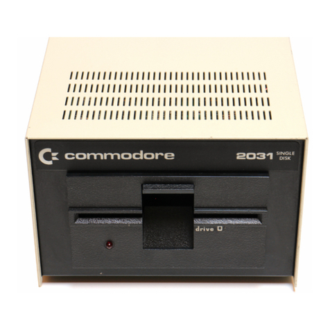
Commodore 2031 User manual

Commodore

Commodore 2031 User manual

Commodore CBM 5 1/4-inch User manual

Commodore

Commodore CBM 5 1/4-inch User manual

Commodore 2040 User manual

Commodore

Commodore 2040 User manual

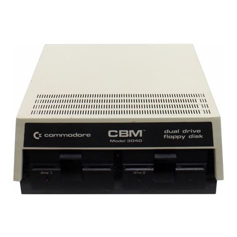
Commodore CBM User manual

Commodore

Commodore CBM User manual

Commodore 1541 User manual

Commodore

Commodore 1541 User manual

Commodore 8050 User manual

Commodore

Commodore 8050 User manual

Commodore 1541-II User manual

Commodore

Commodore 1541-II User manual

Commodore 1540 User manual

Commodore

Commodore 1540 User manual

Commodore 1571 User manual

Commodore

Commodore 1571 User manual

Commodore 910 User manual

Commodore

Commodore 910 User manual

Commodore CBM 2040 User manual

Commodore

Commodore CBM 2040 User manual
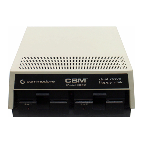
Commodore Amiga 1010 User manual

Commodore

Commodore Amiga 1010 User manual

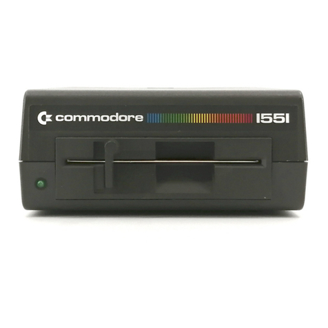
Commodore 1551 User manual

Commodore

Commodore 1551 User manual

Commodore 1541 User manual

Commodore

Commodore 1541 User manual

Commodore 1541 User manual

Commodore

Commodore 1541 User manual

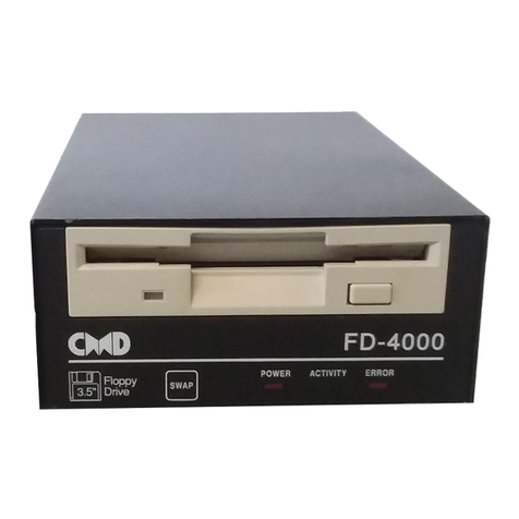
Commodore FD-4000 User manual

Commodore

Commodore FD-4000 User manual
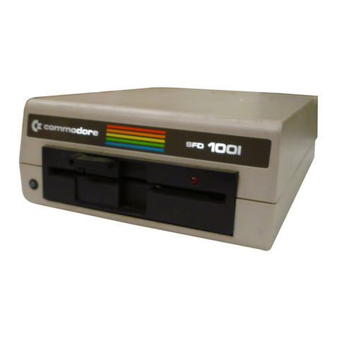
Commodore 1541-II User manual

Commodore

Commodore 1541-II User manual

Commodore 1541 User manual

Commodore

Commodore 1541 User manual

Commodore VIC-20 User manual

Commodore

Commodore VIC-20 User manual

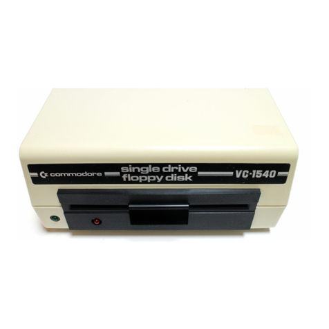
Commodore vic-1540 User manual

Commodore

Commodore vic-1540 User manual

Commodore CBM 2040 User manual

Commodore

Commodore CBM 2040 User manual

Commodore 2040 User manual

Commodore

Commodore 2040 User manual
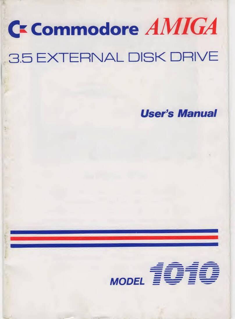
Commodore 8050 User manual

Commodore

Commodore 8050 User manual
Commodore 1581 User manual

Commodore

Commodore 1581 User manual

Popular Floppy Disk Drive manuals by other brands
Teac FD-235 Series installation guide

Teac

Teac FD-235 Series installation guide

Epson Zip-100P (Parallel) Installation & user guide

Epson

Epson Zip-100P (Parallel) Installation & user guide

Qume DataTrak 8 manual

Qume

Qume DataTrak 8 manual

Panasonic CF-VFS711 operating instructions

Panasonic

Panasonic CF-VFS711 operating instructions

MITS 88-DCDD Operator's manual

MITS

MITS 88-DCDD Operator's manual

Fujitsu M255XK Customer Engineering Manual

Fujitsu

Fujitsu M255XK Customer Engineering Manual

Digital Electronics Corporation PL-FD200 installation guide

Digital Electronics Corporation

Digital Electronics Corporation PL-FD200 installation guide

manuals.online logo
manuals.online logoBrands
  • About & Mission
  • Contact us
  • Privacy Policy
  • Terms and Conditions

Copyright 2025 Manuals.Online. All Rights Reserved.