manuals.online logo
Brands
  1. Home
  2. •
  3. Brands
  4. •
  5. Commodore
  6. •
  7. Floppy Disk Drive
  8. •
  9. Commodore AMIGA 2010 User manual

Commodore AMIGA 2010 User manual

CKCommodore
31/2"FLOPPY DISK DRIVE
installation guide
COMMODORE
AMIGA 2010
31/2"FLOPPY DISK DRIVE
INSTALLATION GUIDE
COPYRIGI IT
This manual Copyright !1987 Commodore-Amiga, Inc., All
Rights Reserved. This document may not, in whole or in part, be
copied, photocopied, reproduced, translated, or reduced to any
electronic medium or machine readable form, without prior con-
sent, in writing, from Commodore-Amiga, Inc.
Amiga is aregistered trademark of Commodore-Amiga, Inc. Com-
modore and the Commodore logo are registered trademarks of
Commodore Electronics Limited. Workbench is atrademark of
Commodore-Amiga, Inc.
WARNING: This equipment has been certified to comply with the
limits for aClass Bcomputing device, pursuant to subpart Jof Part
15 of FCC rules. Operation with non-certified equipment is likely
to result in interference to radio and TV reception.
Table of Contents
1. Introduction 1
2. How to Install Your A2010 Floppy Disk Drive ... 2
Removing the Amiga's Cover .2
Installing the A2010 4
Using Set 1Hardware 5
Using Set 2Hardware 6
Replacing the Metal Plate 6
Connecting the A2010 to the A2000 7
Placing the Jumper on the A2000 Board 8
3. Running aTest of the A2010 12
4. Technical Specifications 14
1. Introduction
The A2010 31
/:" Floppy Disk Drive is identical to the
internal floppy drive that is already installed inside
your Amiga 2000. By adding the A2010 to your Amiga
2000, you eliminate the disk swapping involved
when using only one floppy drive. With two drives
you can access information and perform disk oper-
ations, such as copying disks, much faster.
The A2010 is easily installed inside the A2000. Before
you begin, check to make sure that you have received
everything:
•A2010 3'/2" floppy disk drive
•Set of hardware (4 screws, 4washers, 4standoffs)
•Jumper
You should also have on hand your Workbench 7"
disk, one blank disk, and one "scratch" disk —adisk
that you will not miss if it is damaged. (A formatted
disk will suffice.)
2. How to Install Your
A2010 Floppy Disk Drive
WARNING: Unplug the Amiga 2000 before install-
ing the A2010. Installing the A2010 with the power
on could cause possible injury to yourself and dam-
age the equipment. Commodore will not be respon-
sible for any damages caused by improper installa-
tion of the A2010. Such improper installation will
void the warranties on both the Amiga 2000 and the
A2010.
Before you start, disconnect the mouse and the key-
board from the front of the Amiga and the power cord
and any peripherals attached in the rear.
Removing the Amiga's Cover
Remove the two screws on the lower left side of the
Amiga that hold the metal cover to its base. Remove
the two screws on the lower right side of the Amiga.
Put the screws and washers aside for later.
Remove the center screw from the rear of the Amiga.
Be careful to unscrew the correct screw as shown.
•T/ •
Turn the Amiga so that you are facing the front of the
machine; the disk drive should be facing you. Grasp
the cover on both sides, slide it towards you, and lift
upward.
If the cover gets stuck, do not force it. Look under the
top of the cover towards the middle. Check to see if
any wires or cables are caught under the small projec-
tion where the middle screw had been attached. If
anything is caught, gently untangle it, and continue
to slide the cover off.
Installing the A2010
Notice the metal plate where the first internal floppy
disk drive is attached. The A2010 will be mounted on
that plate to the left of the first floppy drive. To secure
the screws that will hold your A2010 in place, you
need to lift up the plate.
Four screws hold the metal plate in place; two on the
right side and two on the left. Remove the four
screws, and gently lift up the plate.
Notice the four slight oblong holes in the plate. The
screws for the A20I0 will go through these slots.
/\r_SErI
II «<
Check the hardware that you received with the
A2010. It will be one of two sets:
SET 1SET 2
4threaded standoffs 4standoff washers
4short screws 4long screws
4flat washers 4flat washers
Using Set 1Hardware
The four standoffs are threaded on each end. One
end of each standoff will be screwed into the A2010.
Ashort screw will be screwed into the other end of
each standoff to hold the A2010 in place.
Screw the four standoffs into the underside of the
A2010. Working from the underside of the metal
plate, hold the A2010 so that it is flush against the
first internal floppy drive.
Put aflat washer over one of the short screws and
insert the screw through the metal plate and into the
standoff. Hand tighten the screw. Repeat this process
with the other three holes. When you have all four
screws in correctly and you are sure the A2010 is
flush against the other drive, tighten the screws.
Using Set 2Hardware
Working from the underside of the plate, put aflat
washer over one of the long screws and insert it
through ahole in the plate. (We suggest starting with
the rear hole immediately next to the first floppy disk
drive.) Place astandoff washer on top of the screw.
Holding the A2010 so that it is flush against the first
floppy drive, place the A2010 on top of the standoff
and hand tighten the screw.
(Repeat this procedure using the front hole immedi-
ately next to the first disk drive. Then move to the
other rear hole, and finish with the remaining front
hole.)
When you are sure that the screws are in correctly
and that the A2010 is flush against the other drive,
lighten all four screws.
Replacing the Metal Plate
After the A2010 is mounted, put the metal plate back
in place, insert the screws, and hand tighten. You
should have some leeway to slide the plate back and
forth, since you need to make sure that the face of the
floppy disk drive is flush with the face of the Amiga.
First, however, you must remove the bezel in the
Amiga's lid that is covering the opening for the
A2010. Simply unscrew the two screws that hold the
bezel in place.
To check that the drives are flush, slide the metal
plate forward, and place the cover over the top of the
machine without replacing the screws. If the disk
drives are not flush with the face of the Amiga, gently
slide them back until they are in place. Carefully lift
off the cover, and tighten the screws holding the
metal plate.
Connecting the A2010 to the A2000
There is a34-pin ribbon wire connector already inside
your A2000. Notice the colored stripe running down
one edge of the cable. Hold the cable so that this
stripe is on the left side as you face the front of the
Amiga. Now, gently slide the ribbon wire connector
onto the connector on the rear of the A2010.
Warning: Be sure to insert the cable gently so that
you don't damage any pins. When you're positive the
cable is oriented properly, insert it all the way.
You must also connect the A2010 to the Amiga's
power supply. Locate the cord running from the
power supply to the first floppy disk drive. There is
another small, four-pin connector on this cord that
you will attach to the power connector on the A2010.
Be careful. If the connector does not fit all the way,
you may have the connector backwards; turn the
connector around, and try again. (When looking at
the power connector from the front of the Amiga, the
orange wire should be towards the left and the yellow
wire should be towards the right.)
Placing the Jumper on the A2000 Board
After the A2010 is properly hooked up, you need to
set ajumper on the A2000 board so that the machine
knows asecond floppy drive has been installed. The
location of the jumper will vary depending on the
part number of your board. The part number is in the
front, left corner of the board, it will be either 312723
or 380705-01.
If your board has part number 312723, you need to
locate the J301 jumper block. (It is just to the left of
the power supply and to the right of the CN303
floppy drive cable connector. In fact, the floppy drive
cable may be covering the jumper block.)
The J301 is normally "open" to signal that only one
internal floppy drive is in place. "Close" the J301 by
placing the small, black jumper over the two upright
prongs, as shown below.
J301 jumper -a^«*:
'~;i'':s;i;l <m%
ILJ^ Nip Jgroj *££ J
If your Amiga has part number 380705-01, you need
to locate the J36 jumper block. To reach the J36 you
must remove the power supply sub-chassis.
Six screws hold the sub-chassis in place. The first two
screws are located above the mouse and keyboard
ports on the front of the Amiga. The remaining four
screws are in the rear of the Amiga as shown below.
Remove all six screws and disconnect any cables that
are attached to the board. Carefully lift out the sub-
chassis.
Locate the J36 using the diagram below.
*
000 w
00 00
OS 00
do m[
BO
ODd
0O0O00DD
D0000000
1(1
Close the J36 by placing the small, black jumper over
the two upright prongs, as shown.
'
J36 jumper
I I
3. Running aTest of the
A2010
After everything is hooked up, you should run a
quick test to make sure the drive is installed properly
You'll need a"scratch" disk, such as aformatted disk,
and ablank disk. (Don't use adisk you don't have a
back-up for!) Without replacing the Amiga's cover,
hook up your monitor and the power. Boot your
Amiga using your Workbench in the first floppy drive
(dfO:).
Take your scratch disk and set the write-protect tab so
that the disk is write inhibited (you should be able to
see through the small hole), and insert the scratch
disk in the A2010 (dfl:). Using either the CLI or the
Workbench, you need to check that the A2010 is
reading the disk properly.
To check the disk using the Workbench, click on the
scratch disk's icon, then choose Info from the Work-
bench menu. When the Info window appears, the
status gadget should show "Read Only". Close the
Info window and remove the scratch disk from the
drive. Change the write-protect disk so that it is write
enabled (there should not be ahole in the disk).
Again select the disk's icon, and choose Info from the
Workbench menu. This time the status gadget should
show "Read/Write."
i?
To check the status using the CLI, simply open aCLI
window and type "info". When the disk is write-
protected, the CLI should display that the disk is read
only. When it is write-enabled, the CLI should dis-
play "read/write".
Finally, try aquick disk copy using the new drive. Put
ascratch disk into the original floppy drive (dfO:), and
put ablank disk into the A2010 (dfl:). Now that you
have two drives, aquick way to copy adisk is to drag
the icon for the disk you want to copy over the icon of
the destination disk. You can also copy the scratch
disk by using the Duplicate command in the Work-
bench menu or the CLI's DISK COPY command.
If any of these tests fail, go back and double-check
your cable and power connections.
Once the A2010 is installed, properly connected, and
tested, you can slide the cover back onto its base and
replace the five screws. Remember to use the washers
to hold the cover tightly in place.
13
4. Technical Specifications
Features &Characteristics
'Single speed MFM read/write format
*880Kbytes formatted storage capacity
'Double sided, double density
"Formatted in 160 tracks with 11 512 byte sectors each
'Reads an entire track at atime
"Supports fast data transfer rates
Power Requirements: Power supplied by Amiga
system
11
34-Pin Ribbon Cable Diagram
R2QGE1
DISH CHANGE <D1*1< IH>
R2Gio
i
,3
J
DISK CtlAHGC RESET
IN USE fc
BRIVT StLECT =3CMOTO* OH 33 s
*
,ii
i13
,13
,17
19
i11
i23
S3
n?
a?
31
33
INDEX •
DRIVE SELECT =lfl
DRIVE SELECT a112
DRIVE SELECT -2(HOTOK ON 2> ^14
16
MOTOR OH t
DIAECTION SELECT IB
STEP 2*
Hit!ltk data fc a
MKlTE OATE 24
TRACK 88 s<
UktTK PROTECT 38
READ DATA 31
SIDE SELECT 33
READV 34
/
i,/} •
LOGIC
CND
13
CsCommodore"
AMIGA
Commodore Business Machines, Inc
1200 Wilson Drive •West Chester. PA 19380
Commodore Business Machines. Inc.
3470 Pharmacy Avenue •Agincourl. Ontario Ml W3G3
380914-03 Printed in JAPAN

Other Commodore Floppy Disk Drive manuals
Commodore 2031 User manual

Commodore

Commodore 2031 User manual

Commodore 1571 User manual

Commodore

Commodore 1571 User manual

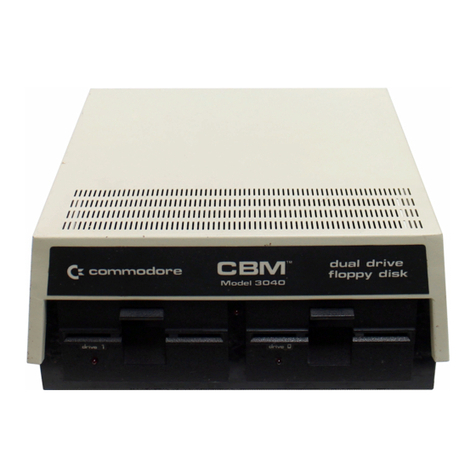
Commodore CBM User manual

Commodore

Commodore CBM User manual

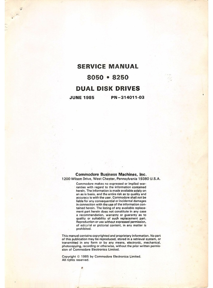
Commodore 8050 User manual

Commodore

Commodore 8050 User manual

Commodore 2040 User manual

Commodore

Commodore 2040 User manual

Commodore 1541-II User manual

Commodore

Commodore 1541-II User manual
Commodore Amiga 1010 User manual

Commodore

Commodore Amiga 1010 User manual

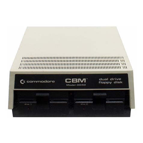
Commodore CBM 2040 User manual

Commodore

Commodore CBM 2040 User manual

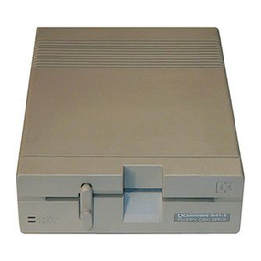
Commodore 1541 User manual

Commodore

Commodore 1541 User manual
Commodore FD-4000 User manual

Commodore

Commodore FD-4000 User manual

Commodore 910 User manual

Commodore

Commodore 910 User manual

Commodore 1541 User manual

Commodore

Commodore 1541 User manual

Commodore vic-1540 User manual

Commodore

Commodore vic-1540 User manual

Commodore 1581 User manual

Commodore

Commodore 1581 User manual

Commodore 1551 User manual

Commodore

Commodore 1551 User manual

Commodore 1541 User manual

Commodore

Commodore 1541 User manual
Commodore 1541-II User manual

Commodore

Commodore 1541-II User manual

Commodore CBM 2040 User manual

Commodore

Commodore CBM 2040 User manual

Commodore 1540 User manual

Commodore

Commodore 1540 User manual

Commodore 1541 User manual

Commodore

Commodore 1541 User manual

Commodore 1581 User manual

Commodore

Commodore 1581 User manual

Commodore 2040 User manual

Commodore

Commodore 2040 User manual

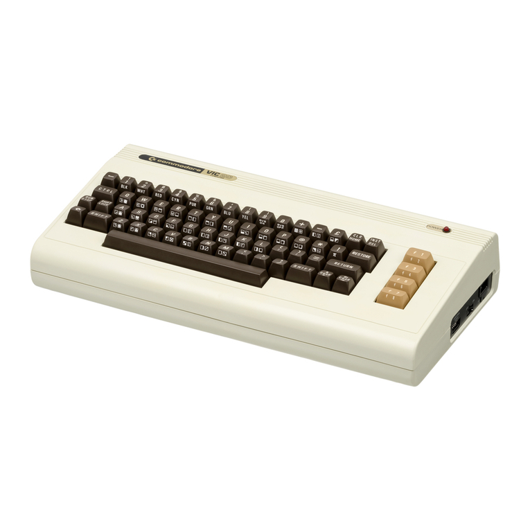
Commodore VIC-20 User manual

Commodore

Commodore VIC-20 User manual
Commodore CBM 5 1/4-inch User manual

Commodore

Commodore CBM 5 1/4-inch User manual

Popular Floppy Disk Drive manuals by other brands
Zenith SM-H-17-4 Service manual

Zenith

Zenith SM-H-17-4 Service manual

VST FDUSB-M user guide

VST

VST FDUSB-M user guide

Sony MFD-20U operating instructions

Sony

Sony MFD-20U operating instructions

V-tech LASER FD 100c user manual

V-tech

V-tech LASER FD 100c user manual

BASF 6106 Technical manual

BASF

BASF 6106 Technical manual

Sharp VR-1FPN Operation manual

Sharp

Sharp VR-1FPN Operation manual

Panasonic CF-VFD Series operating instructions

Panasonic

Panasonic CF-VFD Series operating instructions

Teac FD-05PUB datasheet

Teac

Teac FD-05PUB datasheet

SWTPC MF-68 Assembly instructions

SWTPC

SWTPC MF-68 Assembly instructions

Mitsumi USB FDD user manual

Mitsumi

Mitsumi USB FDD user manual

Tandy Portable Disk Drive 2 Operation manual

Tandy

Tandy Portable Disk Drive 2 Operation manual

Sony MPF920-Z User’s Guide user guide

Sony

Sony MPF920-Z User’s Guide user guide

manuals.online logo
manuals.online logoBrands
  • About & Mission
  • Contact us
  • Privacy Policy
  • Terms and Conditions

Copyright 2025 Manuals.Online. All Rights Reserved.