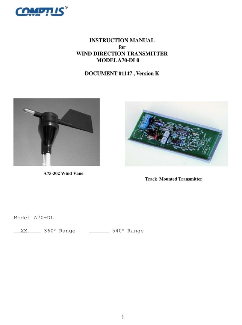
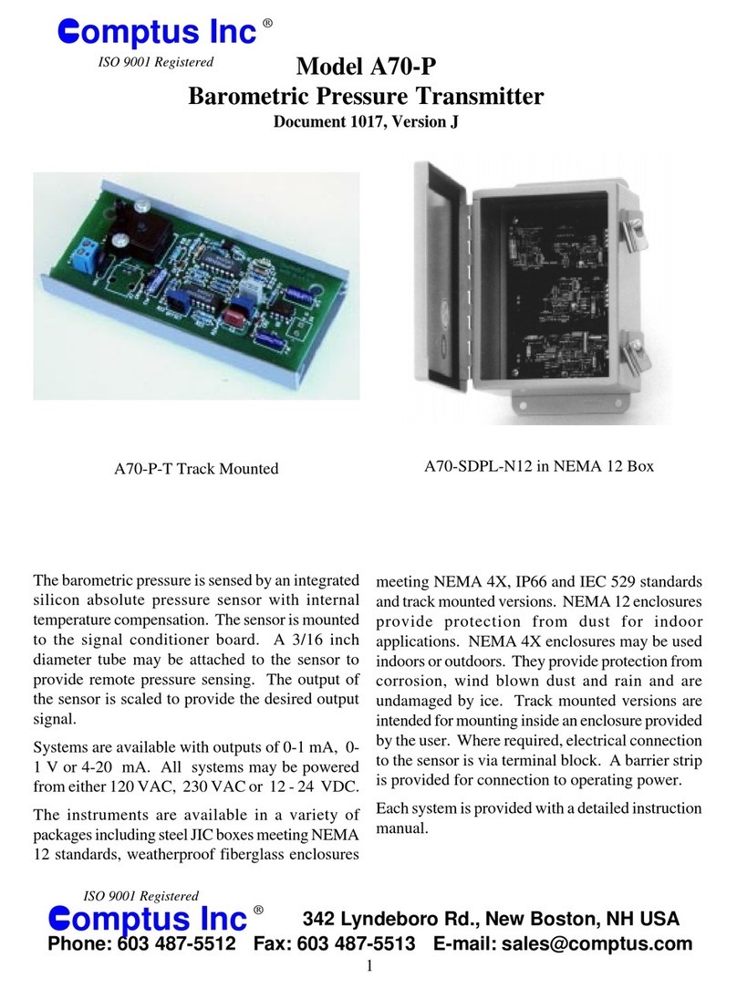
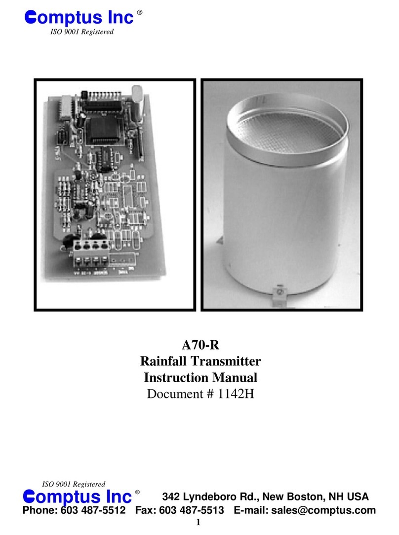
Comptus A70-SDL Series User manual

1
INSTRUCTION MANUAL
for
WINDSPEED&DIRECTIONTRANSMITTER
MODELA70-SDL
DOCUMENT # 1278, Version D
A70-SDPL-N12 in NEMA 12 Box
A75-104Anemometer
A75-302WindVane
®

2
Figure1
RecorderTracewithPredominate
NorthWind
540oScale 360oScale
..
. .
..
. .
. .
. .
. .
N E S W N E S N E S W N
Figure2
RecorderTracewith Predominate
SouthWind
540oScale 360oScale
. .
. .
. .
. .
. .
. .
. .
. .
N E S W N E S N E S W N
INTRODUCTION
TheModelA70-SDLsystemprovides electrical
signalsproportionaltowindspeed anddirection.
Itacceptssignals fromanemometerswithAC
generators.
Thetranslatorwilloperatewithmostpotentiometric
typewind vanes.TheTranslatormaybe inone of
severalpackages. It may betrackmounted for
installationinanexistingenclosure. Itmaybe
suppliedin asteelNEMA 12JIC boxfor inside
deploymentor in asteel NEMA4box whena
weatherproof boxis required.
Thetransmitterconvertstheinformationfromthe
sensorsto 4-20ma signalsproportional towind
speedand direction. Twowinddirection ranges, 0-
360oand 0 - 540oare available. The 540orange is
recommendedif achartrecorderwillrecord wind
direction. Thisrangereduces transitionsfromzero
tofullscale whenthe windisfrom theNorth,
preventingtheentirechartfrombeing “painted.”
The360orangeisrecommendedwhen wind
directioniselectronicallyrecorded.The 360orange
providesthe bestresolutionand theleast cost. The
540orangeis bestwhen abrupttransitions fromzero
tofullscaleareundesirable.

3
SPECIFICATIONS
OperatingPower:
Model A70-SDL1: 10 - 15 VDC
ModelA70-SDL6: 120 VAC, 50/60 Hz
ModelA70-SDL7: 230 VAC, 50/60 Hz
InputDevice:AnemometerwithACGenerator
ComptusA75-104
MaximumModel40
Qualimetrics Model2102
RMYoungWindMonitor
PotentiometricWindVane:
ComptusModelA75-302
QualimetricsModel2102
RMYoungWindMonitor
Output: Speed4-20ma ,Azimuth4-20 ma
Accuracy:Electronics +1%
Sensor:seeseparate specs.
A96-100PSurgeArrestor
Loop Resistance:
300 ohms Max.
TemperatureRange:
Electronics 0/60oC standard
-40/70oC extended
Sensors: see separate specs.
Dimensions: 3" WX 4.5" LX 11.5" D (N12)
5”WX 7” LX1” H (Trackmount)
Weight:Transmitter 8# (NEMA12 Steel Box)
Transmitter1/4#(TrackMount)
Connectors: Barrier Strip toAcceptAWG #14 or
smallerwire
Accessories: A96lightning arrestorrecommended
forsensor protection

4
DESCRIPTION
TheA70-SDLSystemconsists ofaanemometer,
windvaneandtransmitter.
The A75-104 Anemometer is arugged three
cup device whoseaccuracy and reliability have
beenproven inwind tunnel and field testsover
manyyears. Theanemometer housingand rotor
are fabricated ofruggedLexan. Therotoris
supported by aberylliumcoppershaftriding in
Teflonbearings.
The anemometer containsa smallAC generator.
The generatorconsists of afour pole magnet
attachedto the rotor shaft. Asthe magnet rotates it
inducesavoltageina coilofwire mountednearby.
Thisvoltage istransmittedtotheelectronics pack-
agevia thesensor cable. Theanemometer issup-
pliedwithan 10inchlongstubmast with0.50”
outsidediameter and60feet ofcable.
The A75-302 WindVaneis injectionmolded of
black ultravioletstabilized Lexan. The wind vane
shaftis supported by two shieldedstainlesssteel
precisionballbearings. Allmaterialsare corrosion
resistant. Thewind vane issupplied with anS-
shapedaluminummast0.50”outsidediameterand
60feetof cable.
The wind vane isdirectly coupled to a precision
conductiveplastic potentiometer located in the
main body. An analog voltagelinearly propor-
tionalto winddirection is produced whena con-
stantexcitationvoltage isappliedto thepotentiom-
eter.
TheTransmitterconvertstheACfrequencyfromthe
anemometertoadccurrent.Variationin theampli-
tudeof thewind speedsignal doesnotaffect the
accuracyofthe outputsignal.Theoutputcurrent
variesfrom 4ma withno windto 20maatfullscale.
TheTransmitterconvertstheoutputvoltage fromthe
windvane,whichisproportional toazimuth,toadc
current. Thecurrentvaries linearlyfrom 4maat
zero degrees to 20 ma at 360 degrees or 540. The
transmitterprovidesa regulateddc voltagefor
excitationofthewinddirection potentiometer.
TheTransmitteris looppowered andprotected from
damageby reverse polarity. The wind speedand
directioncircuitsaretotally separateandelectrically
isolatedfrom oneanother. Allcircuitsare protected
fromdamageby highvoltagetransients suchas
lightningbymetaloxidevaristors. Theavailable
NEMA12 enclosure hastwo 1/2"romex connec-
torslocated on thebottomof the boxthat provide
entryforcabling.

5
Figure3
SensorMounting

6
Figure4
Poor WindSensorPlacement
OverVerticalWall

7
INSTALLATION
SENSORS
Thesensors shouldbe mountedat thepoint atwhich
itisdesiredtosample thewind. Typically,it is
locatedas highas feasibleand wellclear ofobstruc-
tions.
Theymaybemountedon anexistingstructure, ona
naturalformation, or ona mast ortower. It is
desirabletomountthemso thatthesupporting
structurewillnotinfluencethewindcharacteristicsin
theirimmediatevicinity. Ifthey aremountedabovea
rooftoporsimilarbuildingstructuretheyshouldbe
highenoughso thatthewinddeflectedoffthe
structurewillnot affectthem,typically 5to10 feet
ormore.
Ifmounted tothesideofa supportingstructure they
shouldbe mountedatleasttenstructure diameters
awayfrom the structurein ordertotake thesensors
outof thedisturbed airaround thestructure. They
shouldbemounted towardtheprevailingwindand
shouldbepositionedsothat theinfluence ofstruc-
turalmembersisminimized.
Ifthesystemisto monitorwindcharacteristics fora
proposedwind poweredgenerator,the altitude
shouldbe at least 30feet above the groundor the
supportingstructure forthewindgeneratortower. If
ahorizontal-axis machineisproposed,itis accepted
practiceto mountthe anemometerhead atthe
machine’scenterof rotation.
Apreferredmountingwhichiscommonly usedisa
telescopictowerforinstallationsuptofortyorfifty
feethigh.Atowercommonlyused forTVantenna
support,consistingofconcentricpiecesoftubing
approximatelytenfeet long,guyedateachsection, is
suitable. Abovethisheightself-supporting orguyed
lightweightstructuraltowerscanbeused.
Ifthe sensors areto bemountedon ametallic tower
considerationmustbegiventogalvaniccorrosion
whichoccursbetweendissimilarmetals. Attachment
ofaluminumboomstogalvanizedsteeltowersusing
stainlesssteel hoseclampsis acceptable.
Forothercombinations ofmetalsrecommended
practiceis toelectrically insulatetheboom fromthe
towerwith aplasticbushingorsheet. Preferably
fabricatea boomfrom thesame materialas the
tower. Thisconsiderationisespeciallyimportantin
locationsexposed tosaltspray andair.
Anemometer
Notethe locationof the1/8"diameterholesinthe
anemometerbase and inthe topofthe stubmast.
Donotpress on theanemometerrotor as the
bearingmay bedamaged. Grasp theanemometer
aboutits lower body andpress it ontothe stub mast.
Alignthe1/8"holesand securetheanemometerto
thestub mastby passingthecotterpinthrough these
holes. Attachthe stub mast tothe tower or other
supportusingthetwostainless steelhoseclamps.
Slidethe protective bootoverthe base ofthe
anemometerafter wiringiscomplete. Tape ittothe
mastto secureit inplace.

8
WiringConsiderations
Thewiretypeisnon-criticalformost applications.
Ifthewiringislocatedinanelectricallynoisy
environmentthenthe useofatwistedpairwith
shieldis recommended. Connecttheshield to
groundatone endonly.Theinsulationshouldbe
sunlightresistant.Polyethyleneorpolyvinylchloride
insulationisrecommended.
Beforeproceedingverifythatthemaximum resis-
tanceofthecurrent loopincludingthewiringand
sensingelementdoesnotexceed themaximum
givenbyFormula1.If thisresistance isexceeded
theloopcurrentwillnotattainfullscale.
WindVane
Itisusually desirabletorelate thewinddirection
readingsto TrueNorth.Ifamagnetic compassis
usedthe deviationfrom TrueNorth mustbe deter-
mined. Atopographicalmapcontainsthisinforma-
tion.For exampleifthedeviationis 15degrees
West, a magneticcompass willindicate 15degrees
whenpointed atTrueNorth. Ifthe deviationis East,
thensubtract itfrom 360to obtainthe readingfor
TrueNorth.
Thebase ofthe windvane hastheletter “N”with an
arrowmolded intoit.Refer toFigure 3.This must
beorientedso that it istowardthe North. The
vane’smountingholesareoriented suchthatthe “S”
mast isona North -Southline with respecttothe
vane.Forinstallationsusinglarge,climbabletowers
thevanemay beorientedbypivotingthe “S”mastin
thehose clamps. Forsmaller towerspivot theentire
toweruntilthe“S”mastisproperlyaligned.
Donotpress on the top ofthe vane as it may
damagethebearings.Toinstallthewind vane,grasp
itabout itslower bodyand pressitwithatwisting
motionontothemast.Alignthe1/8"holesinthe
baseof thewindvanewiththeholesin the“S” mast.
Securethe vane tothe mastbypassing thecotter pin
throughtheholes.
Slidethe protective bootover the baseof thewind
vaneafter wiringis complete. Tapeit’s basetothe
mastto secureit inplace.

9
Anemometer
1. Refer to Figures 3 & 5. Connect the sensor cable
to the anemometer using the end with the attached
lugs. Polarity is not important. There are two brass
studswith4-40 threadthatextendfrom thebottomof
theanemometer housing.Attach the sensorcableto
thesestuds beingcarefulto tightenonly the outer#4
hex nut to 3 inch-pounds torque. If the inner nut is
loosenedorthe nutsaretightened simultaneouslythe
studmay rotate. This may resultin a poorelectrical
connectioninside theanemometer. See Figure3.
2.Connectthe anemometer cabletoterminals X3.1
&X3.2ofthetransmittercircuitboard. Polarityisnot
important.
WindVane
It is recommended that the system be as-
sembledandtestedonthe ground before final
installation.
1. Refer to Figures 3 & 5. Connect the Red wire
ofthesignal cable to theDirectionVanePositive
terminal.Tightenwindvaneterminalto3inch
pounds.
2. Connect the Green (or White) to the Direc-
tionVaneNegativeterminal.Tightenwindvane
terminalto3 inchpounds.
3. ConnecttheBlack wire ofthesignal cable to
theDirectionVaneSignal terminal.Tightenwind
vaneterminalto 3inchpounds.
4. Connect the Redwire fromthe wind vane to
transmitterboard terminal X3.3 “+”.
5.Connectthe Black lead fromthewind vane to
thetransmitter boardterminal X3.5 marked SIG”.
6. ConnecttheGreen(orWhite)lead from the
windvanetotransmitterboard terminal X3.4
marked“-”.
Shouldadditional cableberequired upto 1000feet
maybecarefullysplicedinto theexistingcable.
Take care to preserve the color code. AWG #18 -
#22stranded copper wirewith shield is recom-
mended.
Securethe sensorcable tothesupporting structure
atintervals offour feet orless. If thecable is
allowedto vibratein thewind abroken cablemay
result.
OperatingPower
Connecta suitable power sourceto the power
terminalstripX2asfollows:
ACOperating Power
X2.1 AC Line 1 or Hot
X2.2 ACLine 2 orNeutral
X2.3 EarthGround
DCOperating Power
X2.4 Positive
X25 Negative
Note: When circuitboard isconfiguredfor only
DCoperatingpower the connector for X2.1, X2,2
X2.3maynot be present.

10
Figure5
ComponentLayout

11
OPERATION
Operationofthesystem isfullyautomaticand
commenceswhenlooppoweris supplied.
ICING
Undersomeconditions operationoftheanemometer
willbe degradedbythe presenceof ice. This most
oftenoccursastheresult offreezing rain. The
conditionquicklyclearswhensunshineheatsthe
anemometercausingthe icetomelt. Thecondition
maypersist forhoursor daysin the absenceof
brightsunshine.Nopermanentdamage isdoneto
theanemometer. Aninfraredheat lampmaybe
installedinapplicationswhereitisnecessaryto
preventicebuild up.
Note:Windspeeds greater than110%ofthe
specifiedmaximummayproduceoutputsindicating
lessthanfullscale.
A70-LPDD
LoopPoweredDigital Display

12
0 25 50
4
12
20
LoopCurrentinmA
Wind Speed
Meters per Second
ForModel A70-SDL/Mthewindspeed may bede-
terminedfromtheoutputcurrent withthe useofFor-
mula#3.
S - Wind Speed in Meters per Second
I -Loopcurrent in mA
S = (I - 4) X 50/16 Formula 3
Figure7
GraphofWindSpeedTransferFunction
Figure6
GraphofWindSpeedTransferFunction
For Model A70-SDL/Ethe wind speed may be de-
terminedfromtheoutputcurrent withthe useofFor-
mula#2.
S-Wind Speed in Miles Per Hour
I -Loopcurrent in mA
S = (I - 4) X 100/16 Formula 2
0 50 100
4
12
20
LoopCurrentinmA
Wind Speed
Miles per Hour

13
0 80 160
4
12
20
LoopCurrentinmA
Wind Speed
Kilometers per Hour
For Model A70-SDL/Kthe wind speed may bede-
terminedfromtheoutputcurrent withthe useofFor-
mula#4.
S-Wind Speed in KilometersPerHour
I -Loopcurrent in mA
S = (I - 4) X 160/16 Formula 5
Figure9
GraphofWindSpeedTransferFunction
0 15 30
4
12
20
L
oop
C
urren
t
i
nm
A
Wind Speed
Meters per Second
For Model A70-SDL/M2 the wind speed may be
determined from the output current with the use of
Formula#3.
S - Wind Speed in Meters per Second
I -Loopcurrent in mA
S = (I - 4) X 30/16 Formula 4
Figure8
GraphofWindSpeedTransferFunction

14
0 180 360
4
12
20
LoopCurrentinmA
Wind Azimuth
Degrees
N E S W N
360 Degree Wind Direction Scale
Thewinddirectionmaybedeterminedfrom the
outputcurrent withthe useof Formula# 6.
D-WindAzimuth inDegrees
I-Loop Current in ma
D = (I - 4) X 360/16 Formula 7
Figure11
GraphofWindDirectionTransferFunction
360oRange
0 50 100
4
12
20
LoopCurrentinmA
Wind Speed
Kilometers per Hour
ForModelA70-SDL/K2the windspeed maybede-
terminedfromtheoutputcurrent withthe useofFor-
mula#5.
S-Wind Speed in KilometersPerHour
I -Loopcurrent in mA
S = (I - 4) X 100/16 Formula 6
Figure10
GraphofWindSpeedTransferFunction

15
Voltage Across Sensing Resistor
I Loop Current in Milliamperes
R Resistance in Ohms
V Voltage inVolts
V = I X R / 1000 Formula 9
Figure13
CurrenttoVoltageTransferFunction
for 100 Ohm Resistor
0 4 8 12 16 20
0.4
1.2
2.0
Voltage
Loop Current
milliamperes
N E S W N E S
0 180 360 540
LoopCurrentinmA
4
12
20
Wind Azimuth
Degrees
540 Degree Wind Direction Scale
Thewinddirectionmaybedeterminedfrom the
outputcurrent withthe useof Formula# 7.
D-WindAzimuth inDegrees
I-Loop Current in ma
D = (I - 4) X 540/16 Formula 8
Figure12
GraphofWindDirectionTransferFunction
540oRange

16
WINDDIRECTIONTRANSMITTER
Gain&ZeroAdjustments
PotentiometerR34 setsthewinddirectionzero.
PotentiometerR40sets thewinddirection gain.
Theadjustmentsmay besealedwith electronic
gradesiliconrubbertoprevent tamperingbyunau-
thorizedpersonnel.
1. RefertoFigure 7. Connect a jumperbetween
terminals4 &5oftheterminal stripmarked “WIND
VANE”. This simulatesasignalcorresponding to
zerodegreesofazimuth.
2. Adjustthe potentiometermarked“DIR. ZERO”
to produce a 4 ma loop current.
3. Connectajumper between terminals 3&5 of
theterminalstrip marked“WINDVANE”.This
simulatesasignalcorrespondingto 359degrees of
azimuth.
4. Adjustthe potentiometer marked“DIR. GAIN”
toproduce20 ma of loopcurrent.
CALIBRATION
Theinstrumentisfullycalibratedatthefactorybefore
shipment. Thefollowingprocedureisprovidedshould
adjustmentbenecessary inthefuture.
WINDSPEEDTRANSMITTER
The wind speed section consists of a frequency to
current converter. Afunction generator frequency
counterand milliampmeter arerequired for calibra-
tion.
Note:Calibration potentiometermay besealedwith
siliconrubber toprevent tamperingby unauthorized
personnel.
1. RefertoFigure 7.With looppowersupplied and
no speed signal, adjust the potentiometer marked
“SPEEDZERO” toproducealoopcurrent of4 mA.
2. Inspect Table 2 and apply a suitable sinusoidal
signalwitha RMSamplitudebetween 3.5and5Vto
simulate the output of the A75-104 Anemometer.
Consultthefactoryforcalibration ofotheranemom-
eters.
3. Adjustthepotentiometermarked“SPEEDGAIN”
toproducea loop current of 20 mA.
Table 2
A75-104AnemometerOutputFrequency
100 MPH 58.54Hz
160 KPH 58.06 Hz
100 KPH 36.29 Hz
50 M/Sec 65.48Hz
MAINTENANCE
Transmitter
Itis recommendedthat theTransmitterbechecked
forcalibration eachyear. RefertoCalibration
sectionfordetails.

17
TROUBLESHOOTINGPHILOSOPHY
Effectivetroubleshootingrequiresthatproblemloca-
tionsbesystematicallyeliminateduntiltheproblemis
found.
Therearefourbasicquestionstoanswerwhentrouble
shooting(Ref.#1):
1. Didit ever work right?
2. Whatarethe symptomsthattellyouit’s notwork-
ingright?
3. Whendid itstart workingbadlyorstopworking?
4. Whatothersymptomsshowedup justbefore,just
after,or atthe sametime asthe failure?
Itis bestto writedownanycluesyoumayobtain. Be
suretowritedownanythingunusual.
Theresponse to question#3 should probablynot be
3:04P.M.. Ausefulresponse mightbe, “Justafter
anelectricalstorm.” or,“Justafterit felloffthe
shelf.”
Doublecheckall thesimplesolutions totheproblem
beforesearching forcomplex ones. Iftheproblem
occursrightafter installation,itprobablyhasa
simplesolution.
Ifan automobileenginecranks,butdoesn’t start,
makesurethereisfuel inthetankbeforereplacing
theengine. Ifthe electronicequipmentdoesn’t
functionverifythat ithaspowerandis turnedon.
Systemscontainingpartswhichcanbequickly
interchangedare easy totroubleshoot. Swap parts
untiltheproblem moves. Thelocation hasthenbeen
narrowedtothe part thatcausedthe problem to
move.
Sometimesthereare multipleproblems. These
revealthemselvesinlayersmuchlikepeelingan
onion.
Itoften helpsto explaintheproblemtoanother
person,even ifthat personisnotknowledgeable
abouttheparticular pieceofequipment.
Thisdoes twothings. First it requiresyou toorga-
nizethesituationsoit canbe explainedtoanother.
Secondly,itmayturnoutthatyouaresofamiliar
withthesituation thatyouhave overlookedthe
obvious. Anotherpersonunfamiliarwith theequip-
mentmay beable tohelp.
If you are unable to solve the problem, put it aside
untilthe nextday. Somenewthoughtswillprobably
occurwhileworkingonanother project.
References
1. “TroubleshootingisMoreEffectivewith the
RightPhilosophy”,RobertA.Pease,Electronic
DesignNews, January 5,1989.

18
TROUBLESHOOTINGCont.
WINDSPEED
LoopCurrent 0mA
FailureDescription
Opencircuitin cable
Nooperating power
Transmitterfailure
LoopCurrent Lessthan4ma
FailureDescription
Lowpowersupply voltage
Loopresistancetoohigh
Transmitterfailure
LoopCurrentConstant4ma
FailureDescription
Anemometercableshorted
Anemometer coilopen
LoopCurrent Constant 20-22ma
FailureDescription
Powerlineinterference
Openanemometer cable
LoopCurrent Greater than 25ma
FailureDescription
Transmitterfailure
LoopCurrentDoesnotreach 20 ma,
otherwiseoperates properly
FailureDescription
Low powersupply voltage
Loop resistancetoo high

19
WIND DIRECTION
LoopCurrent 0ma (constant):
FailureDescription
Opencircuitin cable
Nooperating power
LoopCurrent 4ma (constant):
FailureDescription
Open in WD EXC or WD SIG wire
WindMonitorpotentiometeropen
LoopCurrent 20ma(constant):
FailureDescription
Openin WDREFwire
LoopCurrentLess than 4 ma:
FailureDescription
Lowpowersupply voltage
Loopresistancetoohigh
LoopCurrent Greaterthan25 ma:
FailureDescription
Transmitterfailure
LoopCurrentDoesnot reach 20 ma,
otherwiseoperatesproperly
FailureDescription
Low powersupply voltage
Loop resistancetoo high
TROUBLESHOOTINGCont.
INCORRECTDIRECTION INDICATION
Checktheresponsewithwind vaneorientationsof
North,South,East andWest. The Northern
orientationisproducedwhenthevaneis alignedwith
themark onthe edgeof thehousing.
Ifthe outputiscorrect forthe Southernorientation,
butincorrect forEast andWest,then thepositive
andnegativeexcitationterminalsareinterchanged.
Iftheoutputsignalisactivefor onlyhalfoftherange,
thenthesignalterminaland oneoftheexcitation
terminalsareinterchanged.
Ifthe outputconstantlyindicatesjustWestofNorth,
thenthenegative excitationconnectionis openorthe
signalterminalisshortcircuitedtothepositive
excitationterminal.
Ifthe outputis constantlyjustEastofNorththenthe
positiveexcitationterminalisopenorthesignal
terminalisshort-circuitedtothenegativeexcitation
terminal.

20
DIRECTIONVANETESTING
Thepotentiometerin thedirection vanehasa
nominalresistance of10000 (10K)ohms.
With thesignalcabletothe directionvanediscon-
nectedfromthetransmitteran ohmmetermaybe
usedto measureapproximately 10000 (10K)ohms
resistancebetween the(+) &(-) excitationtermi-
nals.
Theresistancebetweenthedirectionvanesignal
leadandeither oftheexcitationterminalsshouldbe
lessthan10000 (10K) ohms.
Iftheresistancevaluesdifferradicallyfromthe
abovethen thevaneorthesignalcablelikely con-
tainsafault.
Thesignalleadofthe windvanewillindicatean
opencircuitifthevane ispositioned inthedead
bandwhich iscenteredabout North.
DIRECTIONVANE SIMULATION
Thewindvanemaybesimulatedusingapotentiom-
eterwith anominal resistanceof10000 (10K)
ohms.
TROUBLESHOOTINGCont.
ANEMOMETERTESTING:
Theanemometerat restshouldexhibitaresistance
of400-600ohms. This can be testedfromthe
translatorend ofthesignalcable. Disconnectcable
fromtranslatoranduseohmmeter. Afluctuating
resistancewillresultiftheanemometerturnsduring
thetest.
Aresistance greaterthan1000ohmsindicatesan
opencircuit (breakincable). If thisoccurs after a
periodof normaloperationthecablemay have
brokenin asection where itwas allowedto vibrate
inthewind.
Aresistance lessthan 100ohms indicatesa short
circuit. Anysplices inthesensorcableshould be
suspectif anopen orshortcircuit occur.
Ifanohmmeter isunavailableconnectanemometer
totranslator witha shortlength ofcable. If problem
isremedied, troubleisin thecable.
ANEMOMETERSIMULATION:
TheA75-104Anemometerproduces anAC signal
whosefrequencyandamplitudeare proportionalto
windspeed. Theinstrument measuresthefrequency
andisrelativelyinsensitivetothesignalsamplitude.
See Table2. The amplitudevaries from0VRMSat
0 MPH to 3.7 V RMS at 102 MPH.
Thissignalmaybesimulatedwithafunctiongenera-
toror atransformerconnected tothe electricutility.
Atransformer witha 6Voutput issold atmost
hardwarestores foruse inhome doorbell circuits.
This manual suits for next models
6
Table of contents
Other Comptus Transmitter manuals
Popular Transmitter manuals by other brands

Daniels
Daniels VT-4B140-00-000 instruction manual

Silicon Laboratories
Silicon Laboratories Si47 Series Programming guide

BWI Eagle
BWI Eagle AIR-EAGLE XLT 441UP-HHED-4-001 Product information bulletin

Evikon
Evikon PluraSens E2618-N2O user manual

Pyle
Pyle PBT90 user manual

Terra Electronics
Terra Electronics MCA101L quick start guide