ComSonics Pathfinder Pro II User manual

CSI Doc. Part # 030-00103-00 Rev A
Pathfinder Pro II
Cable & Pipe Locator
User Guide

2
800.336.9681 www.comsonics.com
Contents
Introduction.........................................................................................................................3
Prepare for Use ..................................................................................................................3
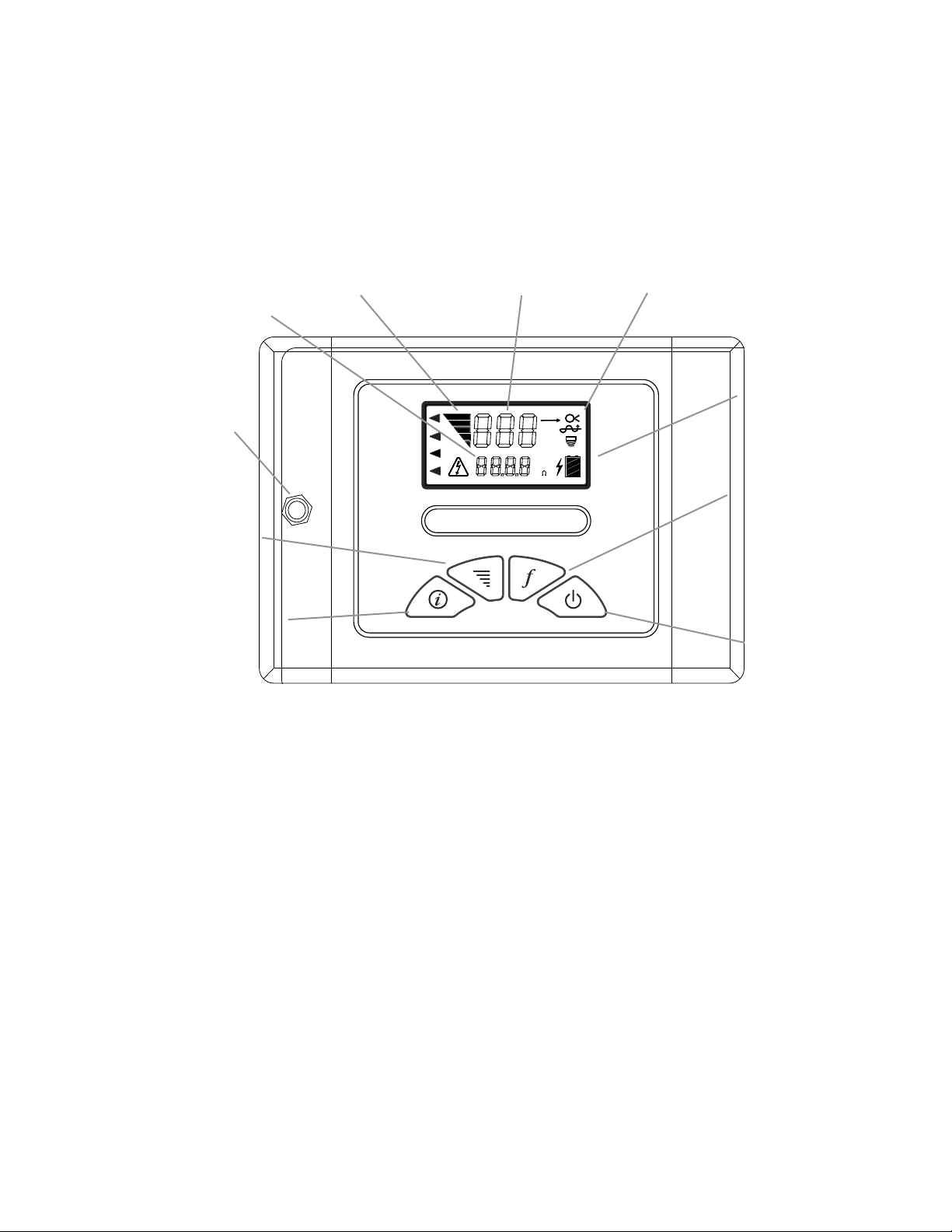
Pathfinder Pro II Transmitter ..............................................................................................4
Pathfinder Pro II Receiver .................................................................................................5
Absolute Signal Strength....................................................................................................6
Gain Change Indication......................................................................................................6
Push Button Depth .............................................................................................................6
Low Battery.........................................................................................................................6
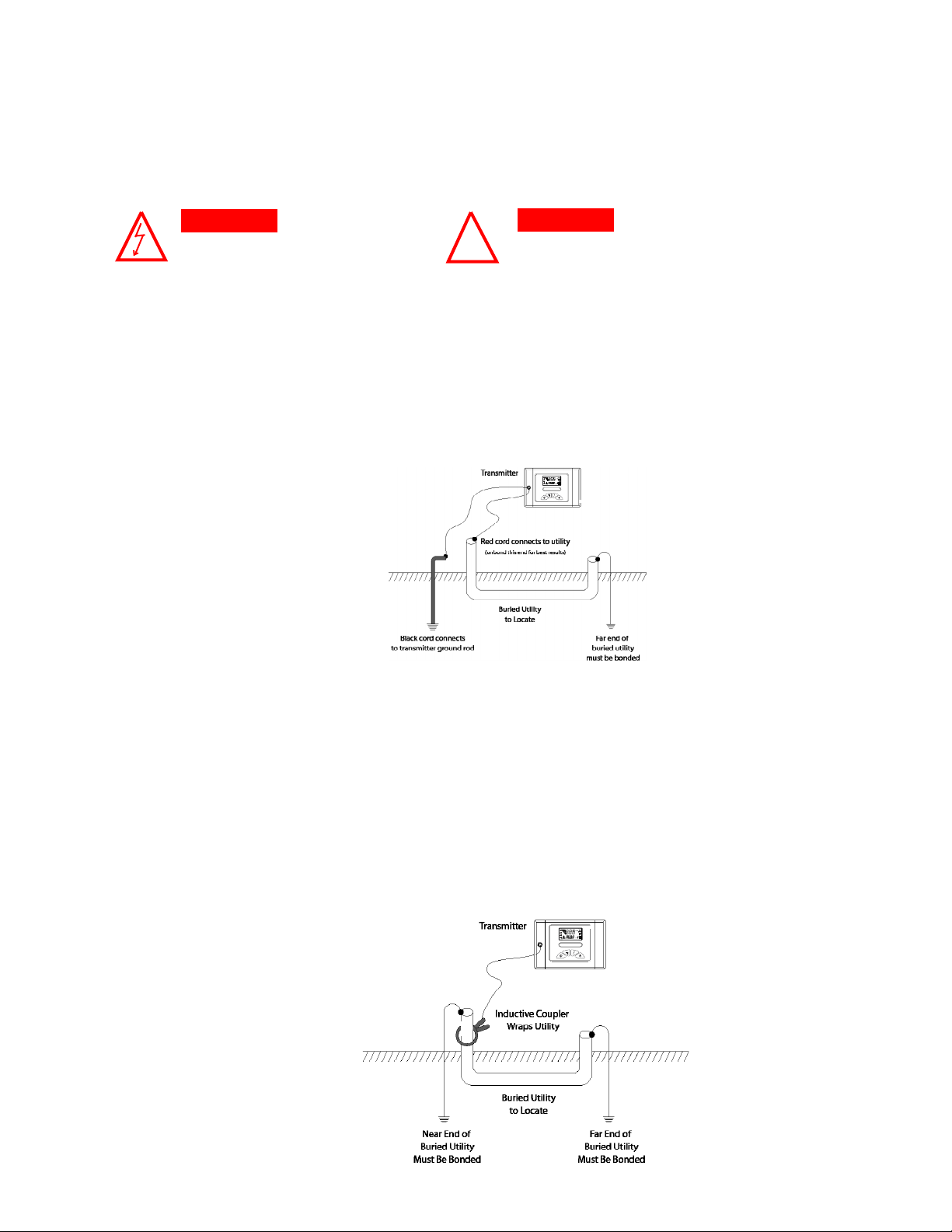
Direct Connection...............................................................................................................7
Flexicoupler Connection.....................................................................................................7
Inductive Connection..........................................................................................................8
Blind Search .......................................................................................................................8
Selecting the Tracing Signal...............................................................................................9
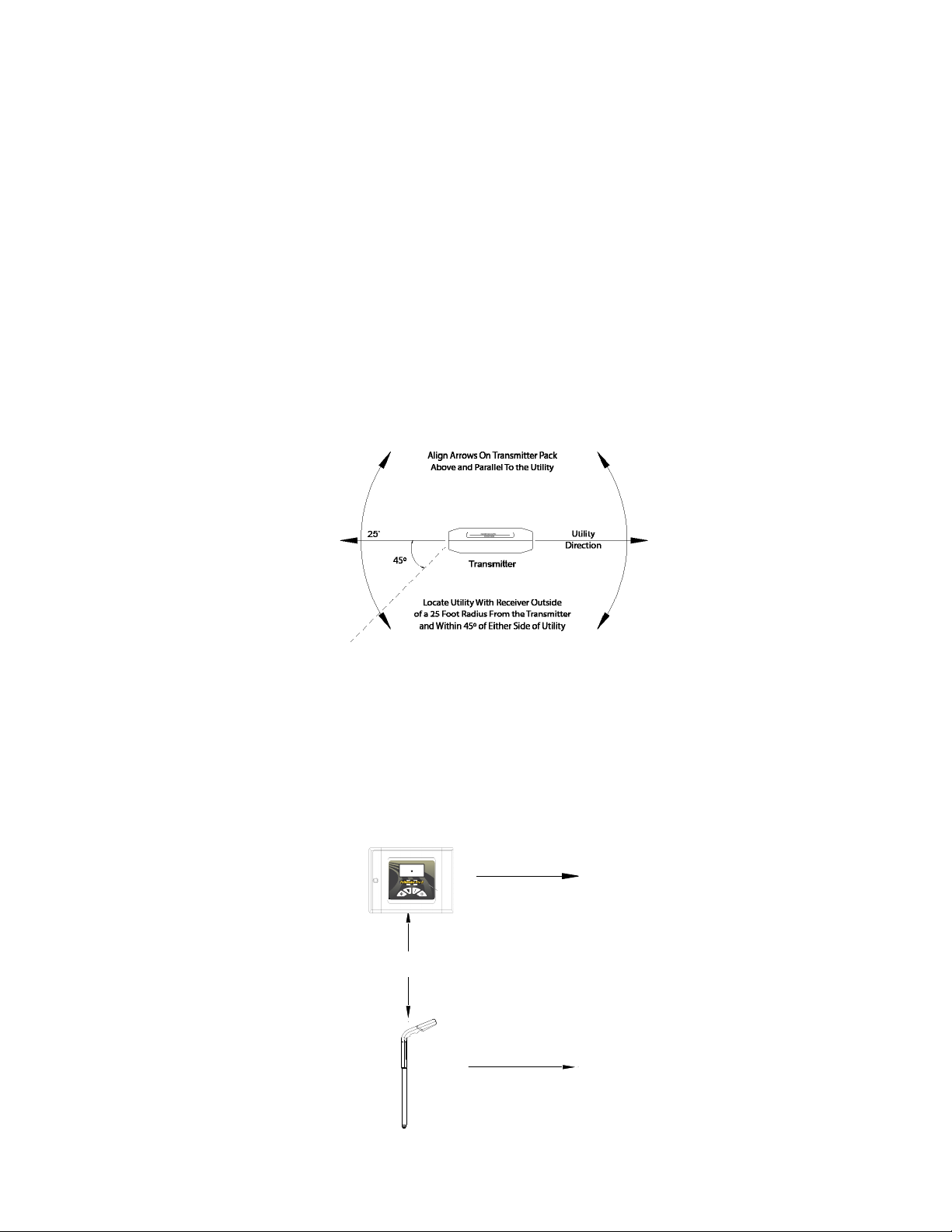
Locating the Cable or Pipe ...............................................................................................10
Peak Mode Locating.........................................................................................................10
Peak Mode Locating Continued .......................................................................................11
Null Mode Locating...........................................................................................................11
Absolute Signal Strength..................................................................................................12
Current Measurement.......................................................................................................12
Gain Change Indication....................................................................................................13
Passive 50/60 Hz Locating...............................................................................................13
Passive Radio Frequency Locating..................................................................................13
Push Button Depth ...........................................................................................................13
Depth Measurement 45º Angle Method............................................................................14
Tilted Magnetic Field Identification ...................................................................................14
Fault Locating...................................................................................................................15
Signal Return Through an Insulated Fault........................................................................15
Ground Return Probe .......................................................................................................15
Ground Return Probe Insertion ........................................................................................16
Ground Return Probe Fault Locating................................................................................17
GRP Receiver Meter Response with Distance.................................................................17
Faults Beneath Paved Surfaces.......................................................................................18
Pathfinder Pro II Transmitter Specifications .....................................................................19
Parts List...........................................................................................................................19
Pathfinder Pro II Receiver Specifications .........................................................................20
Warranty ...........................................................................................................................21
Technical Support .............................................................................................................21
Return Information............................................................................................................21

3
800.336.9681 www.comsonics.com
Introduction
Congratulations on the purchase of your new Pathfinder Pro II. The Pathfinder Pro II is specially designed
to detect buried utilities. This device may detect buried power cables, CATV cables, gas and water
pipes, telephone cables, fiber optic cables with sheath.
The Transmitter emits a signal. The Receiver detects the signal. You can locate the relative position of
the buried utility by following the tracing signal.
Prepare for Use
Unpack your new Pathfinder Pro II Pipe and Cable Locator . Make sure there is no shipping damage
and all the parts are included. See Parts List on page 19.
Locate the battery compartment on the back of the Receiver and back of the Transmitter. Open the
compartment using a phillips screwdriver. Install the “C” batteries as marked.
Note: For longer battery life and reliable operation under adverse conditions, use only alkaline batteries.
Electric shock hazard:
• Toolisdesignedtodetectelectromagneticeldemittedfromburiedmetallic
utilities. There are buried cables, pipes, and utilities this instrument CANNOT
detect.
•LOCATING is not an exact science. The only certain way to be sure of the
existence, location, or depth of buried utilities is to carefully expose (dig up)
the utility.
•De-energize any circuits in or around the work area.
•Do not expose tool to rain or moisture.
•Use tool only for intended purpose as described in this guide
Failure to observe these warnings could result in severe injury or death.
Disclaimer Of liability
ComSonics, Inc. shall not be liable to any person for any incidental, indirect, special,
exemplary or consequential damages, or injury of any type whatsoever, and caused
directly or indirectly by Products sold or supplied by ComSonics, Inc.
!WARNING

4
800.336.9681 www.comsonics.com
Pathfinder Pro II Transmitter
Controls and Indicators
TX OUTPUT JACK
The Red/Black Cord, Coupler and Flexicoupler connects here to create a direct connect or
coupler inductive circuit on the buried utility.
TX ON
Frequency and other LCD segments visible indicates unit is on.
FREQUENCY SELECTOR
Selects frequencies by toggle through available frequencies. 815 Hz, 8 kHz, 33 kHz & 82 kHz are
standard on the Pathfinder Pro II.
LOAD RATE INDICATOR
The Load Rate Indicator symbol flashes to indicate signal transmission via coupler induction or
direct connection.
OUTPUT SIGNAL LEVEL CONTROL
The OUTPUT SIGNAL LEVEL CONTROL adjusts the power output from the Transmitter.
RELATIVE RESISTANCE, VOLTAGE AND CURRENT METER ibutton
The Transmitter can display the resistance, voltage and amperage of the transmitted frequency.
NOTE: This is a relative measurement based on the feedback from the transmitted signal.
Power On & Off
Frequency
Selector
8869
kM
v
mA
DFF
kHz
F. 1
F. 2
Pathfinder Pro II
Battery Condition
Indicator
Load Rate
Indicators
Output Signal
Level Control
Relative
Resistance,
Voltage,
Current
Tx Output Jack
Frequency
Indicator
Output Signal
Indicator
Relative Resistance,
Voltage, Current

5
800.336.9681 www.comsonics.com
Pathfinder Pro II Receiver
Controls and Indicators
ON/OFF Button
The unit will load settings from previous usage.
Note: Automatic shut off after 10 minute of no use.
FREQUENCY Button
Toggles through available active and passive frequencies.
82 kHz, 33 kHz , 8 kHz, 815 Hz, 50/60 Hz and RF.
MODE Button
Toggle through available mode.
PEAK, PINPOINT PEAK, NULL, locating modes.
DEPTH Button
DEPTH function will first momentarily display the depth mode (Line [LIN] and then display depth mea-
surement. To change the Depth Measurement from English to Metric, hold the Depth Key for ten sec-
onds.
GAIN Button (Up or Down)
Adjusts the gain up or down. If the signal strength shows as “ --- ” on the display, pressing the GAIN will
automatically adjust to 85% on the scale display.
CURRENT (SHIFT Button + DEPTH Button)
Measure the relative amount of transmitted current.
VOLUME (SHIFT Button + MODE Button)
Toggle volume through High, Medium, Low and Off.
BACKLIGHT (SHIFT Button + FREQUENCY Button)
Hold the SHIFT Key and press the CURRENT key to toggle on and off the back light.
DISPLAYS ABSOLUTE
SIGNAL STRENGTH
OR DEPTH
ADJUSTS GAIN UP OR
DOWN
ON/OFF BUTTON
MEASURES DEPTH
(+ Shift Key
MEASURES
CURRENT)
RELATIVE SIGNAL
STRENGTH BAR GRAPH
(single bar shows gain
setting)
mA
cm
SON
DFF
ACC
kHz
FREQUENCY SELECTOR
(+ Shift Key
toggles on/off
backlight)
OPERATION MODE
Displays selected
operation avail-
able to model
MODE SELECTOR
(+ Shift Key
toggles volume)
SHIFT KEY
Hold while select-
ing secondary key
functions
DISPLAYS SELECTED
FREQUENCY

6
800.336.9681 www.comsonics.com
Absolute Signal Strength
The Receiver provides the operator with a direct measurement of the Receiver’s signal strength. The
measurement is displayed with three numerical digits (ex: 485) located at the top of the LCD display.
The measurement range is from 0 to 999 indicating a very weak signal (0) to a very strong signal (999).
Absolute Signal Strength is independent of the Gain setting or meter reading. It gives the operator
information about the actual amount of signal being radiated from the conductor and received by
the Receiver.
Measuring Absolute Signal Strength at any time is done by reading the number at the top of the LCD
display. The Absolute Signal Strength will not be displayed if the meter reading is too high or too low.
Adjust the Gain to move the meter reading to mid-scale. The numerical display will change from ‘---’
to a valid measurement.
The GAIN up and down buttons are used to increase and decrease the gain in small amounts. If the
meter reading is very low, pressing the Gain up button will center the meter reading to mid-scale.
Likewise, if the meter reading is very high, pressing the Gain down button will center the meter reading
to mid-scale.
Gain Change Indication
The Receiver can measure depth with the push of a button. The depth is displayed at the top of
the LCD display in feet or inches. Push button depth is useful in quickly determining the depth of the
conductor during path locating.
To change the Depth Measurement from English to Metric, hold the Depth Key for ten seconds and
the next setting will appear.
Caution must be exercised when using the push button depth feature, as tilted magnetic fields and
adjacent conductors can significantly influence this measurement. The operator should periodically
check for adjacent conductors and tilted magnetic fields when taking push button depth readings.
Push Button Depth
Low Battery
The Receiver indicates low battery condition by displaying "LO BAT" in the three digit Signal Strength
Display at the top of the LCD screen.

7
800.336.9681 www.comsonics.com
Direct Connection
Direct Connection is the most reliable method of signal application. This method is relatively free of
interference. The greatest amount of signal strength can be achieved by this method. All frequencies may
be used. The far end of the utility must be grounded.
Connect the Red Test Cord to an existing ground point or an exposed metallic section of the utility . Place
the Ground Rod approximately 10 feet from this point, at an angle of 90º to the buried cable or pipe. Push
the Ground Rod into the ground 8 to 10 inches. Connect the Black Test Cord to the Ground Rod.
Plug the Red/Black Test Cord into the TX Output Jack. Power on the transmitter and select the Frequency.
The Power Output Indicator, Load Rate Indicator and the Frequency will be displayed.
Flexicoupler Connection
The optional Flexicoupler and Hard Coupler are very easy to use, and services are not interrupted.
The operation range is shorter than for Direct Connection methods. The tracing signal can be affected
by neighboring cables and pipes. The Red/Black Test Cord or the Ground Rod are not needed for this
method.
Successful coupler operation requires an insulated conductor that is grounded on both near and far ends.
Loop the Flexicoupler around the cable and connect the two ends, or clamp the Hard Coupler around
the cable. It is important to connect the coupler around the cable needing to be traced. Connect the
coupler around the wire closer to the outgoing cable not near the system ground. The result will be a
stronger signal. By connecting near the grounding, the range will also be shorter, and difficulty may arise
determining one cable from another.
Plug the Coupler Test Cord into the TX Output Jack. Always select the frequency designated by the
coupler. The most common is the 82 kHz FREQUENCY, but couplers are available in multiple frequencies.
DO NOT CONNECT TO LIVE OR
ENERGIZED POWER CABLES
CAUTION !ALWAYS TURN OFF TRANSMITTER BEFORE
CONNECTING AND DISCONNECTING TEST LEADS
CAUTION
kM
v
mA
DFF
kHz
F.1
F.2
Pathfinder Pro II
kM
v
mA
DFF
kHz
F.1
F.2
Pathfinder Pro II

8
800.336.9681 www.comsonics.com
Inductive Connection
This method is convenient to use, and services are not interrupted. No test cords or connections are
needed. The cable or pipe must have good insulation or non-conductive coating, or the operating
range will be short.
Turn the Transmitter ON. Select the 82 kHz frequency. Place Transmitter on its side as close as possible
to the path of the cable or pipe. Align the arrows on the side of the transmitter in line with the cable or
pipe. First, locate the broad Transmitter Null, then move toward the expected cable path while looking
for the signal carried by the cable.
Start tracing the path with the Receiver 25 feet from the Transmitter. Search in the 90º zone. Locate the
cable or pipe, and follow the path. If the signal becomes weak, move the Transmitter to a point 25 feet
behind the last strong signal, and continue searching.
The Blind Search locating technique is used if the operator is not aware if a buried utility exists. Two
people are needed for this technique. The Transmitter and the Receiver are held 25 feet away from
each other. Each operator walks at the same rate keeping a distance of 25 feet from each other.
When the Receiver gives an audio response, then a buried utility is present between the Receiver and
the Transmitter.
Blind Search
TRANSMITTER
25 Feet (7.5 Meters) Between Transmitter and Receiver
RECEIVER
8869

9
800.336.9681 www.comsonics.com
Selecting the Tracing Signal
The choice of 815 Hz, 8 kHz, 33 kHz or 82 kHz Frequency is dependent on the conditions of the locate.
The 815 Hz, 8 kHz, 33 kHz and 82 kHz signals each have their advantages. It is recommended to begin
by using the 815 Hz signal, and continue as long as you are confident in the results. If the signal is very
weak try to adjust the connection or grounding. If there is no improvement in signal then try 8 kHz or 33
kHz. Repeat adjustments of ground and connection point again until switching to 82 kHz.
815 Hz (lower frequency) signal is usually preferred to the 8 kHz (mid-range frequency) and 82 kHz (high
frequency) signal, because it is much less susceptible to locating errors caused by nearby cables or
pipes. The 815 Hz locating range is also much longer than the 82 kHz signal. The 815 Hz signal will not
travel well through disconnected shield bonds or insulated pipe bushing.
8 kHz and 33 kHz takes the best of both high and low frequency. This mid range frequency is not very
susceptible to bleed off or coupling, but it can jump impedance on the utility better than the 815 Hz. It
is still best to use 815 Hz, but 8 kHz is one of the most common frequencies used to locate coaxial cable
and telecom pairs.
The 82 kHz (higher frequency) is sometimes better than the 815 Hz (lower frequency) for locating sharp
corners in cables or pipes. The 82 kHz signal is also better for “jumping” disconnected shield bonds or
grounds, or tracing signal may indicate one of these characteristics. The locating range is quite short
for the 82 kHz signal so the Transmitter must be repositioned more often during the tracing operation.
This frequency is also useful for applying a signal using the Flexicoupler or the Hard Coupler.

10
800.336.9681 www.comsonics.com
Locating the Cable or Pipe
Make sure the Transmitter is connected and in the ON position. Then move approximately 15 feet (4.5
meters) away from the Transmitter along the path. (Move about 25 feet (7.5 meters) for the Inductive
search mode.)
Hold the Receiver so that you can see the LCD bar graph and controls easily. Make sure the Receiver
and the Transmitter Frequency are both set for the same Frequency, either 815 Hz (lower), 8 kHz, 33 kHz
or 82 kHz (higher). Or select a passive locating mode which does not require the Transmitter.
Selecting the Locating Mode (Peak or Null)
Press the MODE button to select a desired Peak or Null locating method.
Peak Mode Locating
Keep the Receiver in a vertical position. Move the Receiver left to right across the path. When the
Receiver is directly above the cable or pipe, rotate the Receiver for a maximum signal. As you move
the Receiver away from the cable path, the meter reading (and audio frequency response) will drop
off.
If you rotate the Receiver while over the cable, a sharp Null will identify the cable’s direction. It is
aligned with the flat side of the Receiver.
CABLE
PATH
MAXIMUM
RECEIVER
SIGNAL DIRECTION
CABLE
NULL SHOWS
PATH
CABLE
Null Mode
Buried cable
Buried cable
Signal over cable
Pinpoint Mode
(End view)
Receiver Max
(End view)
Receiver Min
Signal over cable
Buried cable
Signal over cable
Peak Mode
(End view)
Receiver Max

11
800.336.9681 www.comsonics.com
If you can no longer trace the path, even with the Gain control set to maximum, connect the
Transmitter to the far end of the path and begin tracing the path back.
Mark the straight sections of the path every few feet. Mark sharp curves, loops, and cable bundles
every few inches. Sharp changes in the path causes the Receiver Peak and Null indicators to behave
differently than when tracing a straight path. Practice on the path that you know has turns and laterals
in it. This will help in recognizing the conditions within the field.
Trace the path by walking away from the Transmitter at a moderate pace. Move the Receiver to the
left and right while walking, following the Peak indications.
As you trace the path, the Peak meter reading may slowly fade as you move away from the Transmitter.
Increase the sensitivity using the Gain button to compensate for changes in signal level. If the Peak
meter readings suddenly change in level (higher or lower), one of the following may have occurred:
a) a junction where the signal divides and goes several directions.
b) a break in the cable or shield.
c) a change in the depth of the cable or pipe.
d) an insulated pipe fitting.
e) a slack loop of cable.
Peak Mode Locating Continued
Move the Receiver left to right across the cable path. When the Receiver is directly above the cable or
pipe, a Null (lowest meter reading and lowest audio tone) will occur. When moving the Receiver to left or
right of the Null point, the meter reading will rise to a maximum point (Peak). The audio tone will also be at its
highest pitch. When the Receiver is moved beyond the Peak, the meter reading will begin to fade.
Trace the path by walking away from the Transmitter at a moderate pace. Move the Receiver to the
left and right when walking, following the Null indications.
As you trace the path, the Peak meter reading may slowly fade as you move away from the Transmitter.
Increase the sensitivity using the Gain button to compensate for changes in signal level. If the Peak
meter readings suddenly change in level (higher or lower), one of the following may have occurred:
a) a junction where the signal divides and goes several directions.
b) a break in the cable or shield.
c) a change in the depth of the cable or pipe.
d) an insulated pipe fitting.
e) a slack loop of cable.
If you can no longer trace the path, even with the Gain control set to maximum, connect the
Transmitter to the far end of the path and begin tracing the path back.
Mark the straight sections of the path every few feet. Mark sharp curves, loops, and cable bundles
every few inches. Sharp changes in the path causes the Receiver Peak and Null indicators to behave
differently than when tracing a straight path. Practice on the path that you know has turns and laterals
in it. This will help in recognizing the conditions within the field.
Null Mode Locating

12
800.336.9681 www.comsonics.com
Absolute Signal Strength
The Receiver provides the operator with a direct measurement of the Receiver’s signal strength. The
measurement is displayed with three numerical digits (ex: 485) located at the top of the LCD display.
The measurement range is from 0 to 999 indicating a very weak signal (0) to a very strong signal (999).
Absolute Signal Strength is independent of the Gain setting or meter reading. It gives the operator
information about the actual amount of signal being radiated from the conductor and received by
the Receiver.
Measuring Absolute Signal Strength at any time is done by reading the number at the top of the LCD
display. The Absolute Signal Strength will not be displayed if the meter reading is too high or too low.
Adjust the Gain to move the meter reading to mid-scale. The numerical display will change from ‘---’
to a valid measurement.
Absolute Signal Strength measurements are more sensitive to signal changes than the meter display.
Peaks and Nulls can be more precisely pin-pointed. This measurement can also be used to monitor
signal loss as the conductor is being traced.
The Receiver contains a feature that is very useful in identifying a desired cable in a field of various
conductors and/or utilities. It is not unusual for the target conductor (the conductor connected to
the transmitter) to induce a signal into nearby conductors in a crowded field. In these instances,
the radiated signal on the conductors close to the surface of the earth, may be stronger than the
Transmitter signal on the target conductor buried deep in the ground. The operator will find two or more
paths and must determine which is the target conductor. By using the current measurement feature of
the Receiver, the operator can determine the amount of 815 Hz, 8 kHz, 33 kHz or 82 kHz current flowing
on the conductors, regardless of the depth. The highest current flow indicates the target conductor.
Begin this measurement by locating the path of the cables to be compared. Mark these locations as
accurately as possible (see the sections on Peak Mode Locating and Null Mode Locating). Place the
Receiver vertically over one of the conductor marks and rest the foot of the locator on the ground.
Holding the Receiver vertical, press and release the CURRENT button. When the meter changes from
a “thermometer” type display to a “bar” type display, hold the Receiver still until the measurement
stabilizes. The blinking bar indicates the signal level on the cable (adjusted for depth). Next, move
to the second cable and repeat the measurement. The blinking bar will show the signal level on the
conductor. In addition, the previous reading is shown as a solid bar. The higher of these two readings
will show which conductor is carrying the greatest locating signal.
Note:
The Receiver is designed to alert the operator of potential current measurement errors. If the display
reads ‘Err’ during a current measurement, the Receiver has detected a condition that could produce
inaccurate readings.
Errors can exist when the conductor signal flow is too small. Check Transmitter hookup and far end
access point for poor connections. This cause of error can be identified by a high Gain setting (80 or
greater on the bar graph display).
The Receiver may also be detecting adjacent cables or is not directly over the target conductor.
Verifying target conductor path precisely before measuring current again.
If at anytime the display reads ‘CAL’, contact ComSonics Support.
Current Measurement

13
800.336.9681 www.comsonics.com
The Receiver is capable of locating power utility frequencies. This mode is useful for locating
underground primary and secondary power utilities. In certain circumstances, this mode will also locate
water pipes, sewer lines, cable television, and telephone. The reason is that common electrical grounds
are sometimes found among these various utilities. Select the 50/60~ (Hz) frequency on the Receiver.
Select Peak mode. Locate the conductor using the Peak mode. This method is useful because of its
speed and convenience. Start at a known reference point and keep in mind that other conductors in
the area may produce this same locating signal.
Note: The Transmitter is not required to locate in this mode.
Passive 50/60 Hz Locating
The GAIN up and down buttons are used to increase and decrease the gain in small amounts. If the
meter reading is very low, pressing the Gain up button will center the meter reading to mid-scale.
Likewise, if the meter reading is very high, pressing the Gain down button will center the meter reading
to mid-scale.
Gain Change Indication
Push Button Depth
The only way to be sure of the depth of a utility is to exposes the utility.
At any given time, the depth readout may be inaccurate.
The Receiver can measure depth with the push of a button. The depth is displayed at the top of the
LCD display in feet or inches (meters and centimeters if requested). Push button depth is useful in quickly
determining the depth of the conductor during path locating.
Begin this measurement by locating the path of the cable or pipe. Move to the location where you
want to measure the depth. Stay at least 15 feet (4.6 meters) away from the Transmitter. Pin-point this
location as accurately as possible (see Peak Mode, Null Mode and Absolute Signal Strength). Place the
Receiver vertically over the conductor and rest the foot of the locator on the ground. While holding the
Receiver vertical, press and release the DEPTH button. The Receiver will briefly indicate a measurement
is being performed and then display the depth at the top of the LCD display.
Caution must be exercised when using the push button depth feature, as tilted magnetic fields and
adjacent conductors can significantly influence this measurement. The operator should periodically
check for adjacent conductors and tilted magnetic fields when taking push button depth readings. For
information on identifying tilted magnetic fields, refer to Tilted Magnetic Field Identification and Depth
Measurement 45º Method.
The Receiver is capable of passively locating metallic utilities where radio frequencies have coupled to
the utility. This mode is useful for sweeping a green area for utilities. In certain circumstances, this mode
will locate water pipes, cable television, gas lines and telephone. This locating option does not always
detect buried utilities even when radio frequencies are present. This method is useful because of its
speed and convenience. Start at a known reference point and keep in mind that other conductors in
the area may produce this same locating signal.
Note: The Transmitter is not required to locate in this mode.
Passive Radio Frequency Locating

14
800.336.9681 www.comsonics.com
Depth Measurement 45º Angle Method
Move to the location you want to measure depth. Stay at least 15 feet away from the Transmitter. Move
the Receiver left to right across the path until the cable is located. Mark the path on the ground as
precisely as possible using the Null Method.
Place the Receiver on the ground with the LCD meter facing up. Position the unit so that the Bubble
Level on top of the meter is centered (45º). Pull the Receiver away from the cable path (at 90º to the
cable path) keeping the Bubble Level centered. When the receiver indicates a Null reading, mark the
location of the receiver’s foot. The distance between the Receiver and the cable path is the depth of
the pipe or cable.
A false depth reading may be caused by nearby buried metallic objects, such as a second cable,
pipe, sewer, fence or railroad track. Confirm the depth measurement by repeating the above steps on
the opposite side of the pipe or cable.
A variance greater than 5 inches in depth measurement may indicate the presence of additional
buried cables, pipes or other objects.
Buried cable or pipe
Earth
locate
Path 1st
Null
Null
centered
Bubble level
2nd
(end view)
Depth
Depth
45°
When adjacent cables or pipes are present, they will sometimes create locating errors. Some of the
Transmitter signal is picked up by the adjacent conductors and is redirected so that it combines with
the original signal. The result is a Tilted Magnetic Field. This is often the reason that numeric depth
readouts are sometimes created in error.
The operator can verify the accuracy of path locate by performing the 45º Angle Method locate
on both sides of the cable path. If the right and left side depth readings agree to within 5 inches,
the path locate is accurate. If the two depth readings do not agree, then dig with care. A closer
locate would be halfway between the two outside depth locate marks.
This is an important technique that should be used to ensure the most accurate location possible.
Tilted Magnetic Field Identification

15
800.336.9681 www.comsonics.com
It is generally a good idea to locate the conductor path before attempting to fault locate. If, during
the path locate, an unusual amount of signal loss occurs, a part of the signal has escaped to ground
in the last several feet.
Note: Signal would go to ground at a grounded splice point, which would act as a fault during the
path and fault locate.
Once the path is determined and there is a general area where a fault is expected, additional current
can be forced to flow through the fault by disconnecting and isolating the far access point. If the
current has no path to ground at the far access point, it will be forced to seek ground at the fault.
This will increase the current in the soil at the fault and detection of the fault. Use 815 Hz when fault
locating.
Signal Return Through an Insulated Fault
To begin fault locating, open the Ground Return Probe (GRP) and attach the Receiver as shown
below. Plug the Ground Return Probe Cord into the GRP handle and into the jack on the grip portion
of the receiver handle. The Ground Return Probe is collapsible for easy transport and storage.
Ground Return Probe
Collapsible Ground Return Probe
PINCH HAZARD - Use CAUtIoN WHeN oPeNINg AND ClosINg tHe gRP
REC.
SLIDE
OUT
CLOSING
OPENING 8870 RECEIVER
SLIDE
REC.
IN CONNECT
CORD
Fault Locating
Fault locating determines the position of an insulated break on an underground conductor. In the
case of an insulation fault, some of the signal will return to the Transmitter attached to the Ground Rod
through a break in the insulation.
BURIED CABLE
FAULT
RETURN PATH THROUGH SOIL
AB
NEAR ACCESS POINT FAR ACCESS POINT
EARTH
BLACK
RED
8869

16
800.336.9681 www.comsonics.com
Ground Return Probe Insertion
Circuitry between the ground spikes provides a path for current in the soil returning to the Ground Rod.
The current enters one spike of the Ground Return Probe and exits the other spike. The GRP should be
inserted into the soil with consistent force and depth.
The current in the soil spreads out from the fault like the spokes of a wheel. The current is highly
concentrated in the soil near the fault as it begins its return, and near the Ground Rod as it finishes its
return. Notice that the current is widely dispersed in the soil between the fault and the Ground Rod.
TRANSMITTER
CABLE FAULT
OR
GROUND
TOP VIEW - EARTH RETURN CURRENTS
EARTH EARTH
CABLE (END VIEW)
THE GROUND RETURN PROBE FRAME
SHOULD BE IN LINE WITH, AND
DIRECTLY ABOVE THE CABLE PATH.
CABLE (SIDE VIEW)
BOTH SPIKES SHOULD EVENLY
PENETRATE THE GROUND AND
MAKE GOOD ELECTRICAL CONTACT.

17
800.336.9681 www.comsonics.com
Use 815 Hz when fault locating. As you walk the path using the GRP, drop the probe every three or
four steps. As you near an area of high current concentration in the soil, the Ground Rod or the fault,
the Receiver will record higher and higher readings. You will find it necessary to reduce the Receiver’s
sensitivity by pressing the Gain Control button. Once the signal starts to increase, you should slow down
and take smaller steps, covering smaller segments of ground to avoid passing the fault.
The Receiver will continue to record higher current readings until one spike of the Ground Return Probe
passes the fault. When one spike of the GRP is on each side of the fault, the currents will subtract and
produce a Null. To record the deepest Null, press the Gain Control button to keep the Null on the meter
scale and move the GRP an inch at a time until the deepest Null is recorded. The fault lies in the center
of the Ground Return Probe spikes.
Ground Return Probe Fault Locating
GRP Receiver Meter Response with Distance
Notice in the figure below, there is a Receiver signal level increase as the Ground Return Probe
approaches a fault and it moves away from the Transmitter. A good cable will allow the locating signal
to slowly decrease with distance from the Transmitter. While this signature pattern must be recognized,
this method is usually more accurate than phase responding to-from types of instruments.
8869
kM
v
mA
DFF
kHz
F.1
F.2
BURIED CABLE
EARTH
BLACK
RED
FAULT
ISOLATED
FAR END
GRP-RECEIVER DISPLAY RESPONSE WITH DISTANCE
PEAK NULL LOWER
PEAK
RELATIVE
SIGNAL
LEVEL
8869
kM
v
mA
DFF
kHz
F.1
F.2
BURIED CABLE
EARTH
BLACK
RED
SHEATH-TO-GROUND FAULT
REAR
SPIKE
FRONT
SPIKE
DISPLAY PEAKS
WHEN FRONT
SPIKE IS
DIRECTLY
OVER FAULT.
DISPLAY NULLS
WHEN GROUND
RETURN PROBE
IS DIRECTLY
OVER FAULT.
DISPLAY PEAKS
WHEN REAR
SPIKE IS
DIRECTLY
OVER FAULT.
NEAR
ACCESS
POINT
FAR
ACCESS
POINT

18
800.336.9681 www.comsonics.com
A potential problem could exist if a fault should lie beneath a paved surface. In this case, the Ground
Return Probe will be used in the dirt at the side of the paved area. Since the return current in the soil
begins its return from the fault - like the spokes of a wheel laying on the ground - equal amounts of
current will enter the GRP if it is placed on the ground and positioned broadside to the fault. At the
point where the directional indication changes the fault will lie on a straight line projected at a right
angle from the center of the GRP. The GRP adjustments can be made by slightly rotating the Ground
Return Probe to find the directional change. The operator should record this line over the paved area.
By repeating this procedure from another location near the paved area, another line will be produced.
The intersection of the two lines is the location of the fault.
Faults Beneath Paved Surfaces
CABLE
PAVED ROAD
GROUND RETURN PROBE IS
POSITIONED FOR A MINIMUM
(NULL) RECEIVER DISPLAY.
GROUND RETURN PROBE IS
POSITIONED FOR A MINIMUM
(NULL) RECEIVER DISPLAY.
SHEATH-TO-GROUND
FAULT

19
800.336.9681 www.comsonics.com
Operating Frequency
Hook-up Method
Output Power
Load Matching
Battery Types
Dimensions
Weight
82 kHz • 33 kHz • 8 kHz • 815 Hz
Automatic from 5 Ωto 2000 Ω
Operating Temperature -4°F to 133ºF (-20ºC to +55ºC)
Battery Life Greater than 30 hours*
High (1 Watt), Med, Low
8 - “C” alkaline batteries
8.4” x 5.57” x 2.6”
2.2 lbs (1 kg)
*Depending on load, frequency and power setting
Direct Connection
Inductive Coupling (with optional coupler)
Transmitter Induction
Pathfinder Pro II Transmitter Specifications
Pathfinder Pro II Cable, Pipe and Fault Locator
Receiver
Transmitter
User Guide
Red/Black Cord (Large Clamp)
Ground Rod
Carry Case Receiver
Carry Case Transmitter
Pathfinder Pro II Accessories
Hard Inductive Clamp (82 kHz)
Hard Inductive Clamp (82 kHz/8 kHz)
Flexicoupler (815 Hz/ 82 kHz
Flexicoupler (82 kHz/ 8 kHz)
Ground Return Probe
Parts List

20
800.336.9681 www.comsonics.com
Pathfinder Pro II Receiver Specifications
Operating Frequency
Antenna Mode
Audio Indication
Operating Temperature
Battery Type
Battery Life
Dimensions
Weight
Signal Strength
Gain Control
Dynamic Range
Depth Measurement
82 kHz • 33 kHz • 8 kHz • 815 Hz • 50/60~ • RF
Variable pitch audio
-4°F to 133ºF (-20ºC to +55ºC)
Continuous 40 hours
Automatic Digital depth readout to 15 feet
(feet/inches & metric)
Manual Triangulation for verification
of automatic readout in congested
environments
Intermittent 82 hours (10 minute auto shut off)
6 - “C” alkaline batteries
30.3” x 3.75” x 9.4”
LCD bar graph
Absolute Signal Strength readout 0-999
up/down button for automatic
centering and manual control
126 dB
3 lbs (1.3 kg)
Null (vertical coil) • Peak (horizontal coil)
Table of contents
Other ComSonics Test Equipment manuals
Popular Test Equipment manuals by other brands

Gossen MetraWatt
Gossen MetraWatt PROFITEST EMOBILITY operating instructions

ATEQ
ATEQ F600 quick start guide

Kenwood
Kenwood DCS-8200 instruction manual

Agilent Technologies
Agilent Technologies E6392B user guide

ACS
ACS Alert J5 Calibration manual

Motomaster
Motomaster ELIMINATOR 011-3008-0 instruction manual

Keysight
Keysight Infiniium 90000A Series Service guide

Test Equipment Depot
Test Equipment Depot GPL-5010 user manual

Keysight Technologies
Keysight Technologies N4891A Getting started

Solo
Solo 461 instructions

Kewtech
Kewtech KT63DL operating instructions

Agilent Technologies
Agilent Technologies Infi niium 9000 Series Quick demo guide