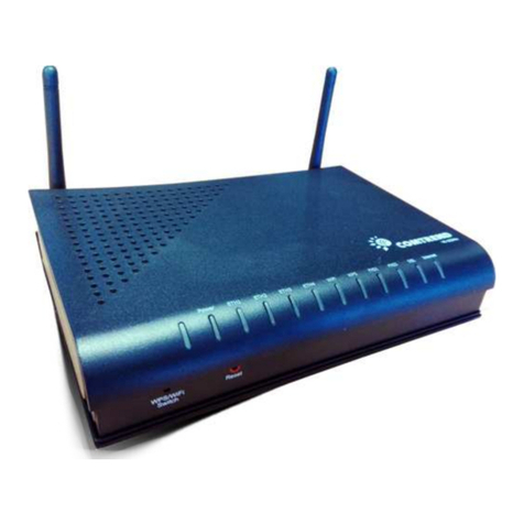
Comtrend Corporation NexusLink 5700 User manual

NexusLink 5700
Wireless ADSL bonding IAD
User’s Manual
Version C1 0, October 5, 2010
260101-001

1
Warning
Before servicing or disassembling this equipment, always disconnect all
power and telephone lines from the device
Use an appropriate power supply and a UL Listed telephone line cord
Specification of the power supply is clearly stated in Appendix C
Preface
This manual provides information to network administrators It covers the
installation, operation and applications of the Wireless ADSL bonding IAD
The individual reading this manual is presumed to have a basic understanding of
telecommunications
This document is subject to change without notice For product update, new
product release, manual revision, software upgrade, technical support, etc , visit
Comtrend Corporation at http://www comtrend com
FCC Interference Statement
This equipment has been tested and found to comply with the limits for a Class B
Digital Device, pursuant to part 15 of the FCC Rules These limits are designed to
provide reasonable protection against harmful interference in a residential
installation This equipment generates, uses and can radiate radio frequency
energy and, if not installed and used in accordance with the instruction, may
cause harmful interference to radio communication However, there is no grantee
that interference will not occur in a particular installation If this equipment dose
cause harmful interference to radio or television reception, which can be
determined by turning the equipment off and on , the user is encouraged to try to
correct the interference by one or more of the following measures:
Reorient or relocate the receiving antenna
Increase the separation between the equipment and receiver
Connect the equipment into an outlet on a circuit different from that to which
the receiver is connected
Consult the dealer or an experienced radio/TV technician for help
FCC Caution: The changes or modifications not expressly approved
by the party responsible for compliance could void the
user's authority to operate the equipment

2
This device complies with Part 15 of the FCC Rules Operation is subject to the
following two conditions:
1 This device may not cause harmful interference
2 This device must accept any interference received, including interference that
may cause undesired operation
FCC Radiation Exposure Statement
To comply with the FCC RF exposure compliance requirements, this device and its
antenna must not be co-located or operating to conjunction with any other
antenna or transmitter
This equipment should be installed and operated with minimum distance
20cmbetween the radiator & your body
Copyright
Copyright© 2010 Comtrend Corporation All rights reserved The information
contained herein is proprietary to Comtrend Corporation No part of this document
may be translated, transcribed, reproduced, in any form, or by any means without
the prior written consent of Comtrend Corporation
Technical support
If you find the product to be inoperable or malfunctioning, please contact a technical
support engineer for immediate service by email at INT-support@comtrend com
Save ur Environment
This symbol means that when the equipment has reached the end of its
useful life, it must be taken to a recycling centre and processed separate
from domestic waste
The cardboard box, the plastic contained in the packaging, and the parts that make
up this device can be recycled in accordance with regionally established regulations
Never throw-out this electronic equipment along with your household waste You
may be subject to penalties or sanctions under the law Instead, ask for
instructions from your municipal government on how to correctly dispose of it
Please be responsible and protect our environment

3
Table of Contents
CHAPTER 1
INTRODUCTION ....................................................................................................6
1.1
F
EATURES
........................................................................................................................................6
1.2
A
PPLICATION
...................................................................................................................................7
1.3
F
RONT
P
ANEL
LED
I
NDICATORS
......................................................................................................8
CHAPTER 2
INSTALLATION ......................................................................................................9
2.1
H
ARDWARE
I
NSTALLATION
..............................................................................................................9
CHAPTER 3
LOGIN VIA WEB BROWSER .............................................................................10
3.1
IP
A
DDRESS
...................................................................................................................................10
3.2
L
OGIN
P
ROCEDURE
........................................................................................................................ 11
CHAPTER 4 DEVICE .........................................................................................................................12
4.1
D
EVICE
S
UMMARY
........................................................................................................................13
4.2
R
ESET
S
TATISTICS
..........................................................................................................................14
4.3
T
ROU LESHOOT
............................................................................................................................15
4.4
W
IRELESS
......................................................................................................................................17
4.4.1 Enable Wireless............................................................................................................. 19
4.4.2 Wireless - Security Configure..................................................................................19
4.4.3 WPS Setup......................................................................................................................22
4.4.4 Wireless - Advanced Configure............................................................................... 26
4.5
R
ESTART
Y
OUR
S
YSTEM
................................................................................................................28
4.6
H
OME
N
ETWORK
...........................................................................................................................30
4.7
G
AMING AND
A
PPLICATIONS
..........................................................................................................32
4. .1 Incoming Traffic Control............................................................................................ 33
4. .2 Outgoing Traffic Control ............................................................................................ 35
4.8
R
ESET
A
CCESS
C
ODE
.....................................................................................................................37
CHAPTER 5 BROADBAND...............................................................................................................39
5.1
S
TATUS
..........................................................................................................................................39
5.2
C
ONFIGURE
...................................................................................................................................40
CHAPTER 6 HOME NETWORK...................................................................................................... 42
6.1
LAN
S
TATUS
.................................................................................................................................42
6.2
C
ONFIGURE
...................................................................................................................................43
6.3
W
IRELESS
S
TATUS
.........................................................................................................................48
6.4
W
IRELESS
C
ONFIGURE
..................................................................................................................49
6.5
W
IRELESS
MAC
F
ILTER
................................................................................................................50
CHAPTER 7 VOIP............................................................................................................................... 52

4
7.1
S
TATUS
..........................................................................................................................................53
7.2
SIP ................................................................................................................................................53
.2.1 Global Parameters ....................................................................................................... 54
.2.2 Service Provider............................................................................................................ 55
7.3
RTCP ............................................................................................................................................ 57
7.3.1 Global Parameters ................................................................................................................57
7.3.2 Service Provider ....................................................................................................................58
7.4
T
ELEPHONE
C
ALLS
........................................................................................................................59
CHAPTER FIREWALL ................................................................................................................... 59
8.1
S
TATUS
..........................................................................................................................................61
8.2
I
N OUND
F
ILTER
...........................................................................................................................61
8.3
O
UT OUND
F
ILTER
........................................................................................................................61
8.4
P
ORT
F
ORWARDING
........................................................................................................................62
8.5
P
ORT
T
RIGGERING
.........................................................................................................................65
CHAPTER 9 MAINTENANCE .......................................................................................................... 67
9.1
T
EST
..............................................................................................................................................67
9.2
DSL............................................................................................................................................... 68
9.2.1 xDSL BER Test ..............................................................................................................69
9.2.2 Reset Statistics ............................................................................................................. 71
9.2.3 Draw Graph Tone ......................................................................................................... 71
9.2.4 Draw Loss of Signal Graph .......................................................................................72
9.2.5 Draw Loss of Frames Graph.....................................................................................72
9.2.6 Loss of Power................................................................................................................. 73
9.3
P
ING
/T
RACEROUTE
/NSL
OOKUP
....................................................................................................74
9.3.1 Ping....................................................................................................................................74
9.3.2 TraceRoot........................................................................................................................ 75
9.3.3 NSLookup........................................................................................................................75
9.4
S
YSTEM
L
OG
.................................................................................................................................76
9.4.1 Refresh............................................................................................................................. 77
9.4.2 Export Syslog................................................................................................................. 77
9.5
P
ASSWORD
.....................................................................................................................................79
9.5.1 Use New Access Code.................................................................................................80
9.5.2 Clear Input...................................................................................................................... 80
9.5.3 Reset to Default Access Code.................................................................................. 80
9.6
U
PGRADE
.......................................................................................................................................81
9.7
R
E OOT
.........................................................................................................................................82
9.8
F
ACTORY
R
ESET
............................................................................................................................83
5
APPENDIX A: FIREWALL ................................................................................................................ 5
APPENDIX B: PIN ASSIGNMENTS ................................................................................................. 9
APPENDIX C: SPECIFICATIONS.................................................................................................... 90
APPENDIX D: SSH CLIENT ............................................................................................................. 93

6
Chapter 1 Introduction
The NexusLink 5700 Wireless ADSL bonding IAD features flexible networking
connectivity with dual ADSL line capability, four 10/100 Ethernet ports, and an
802 11g wireless LAN access point It has robust routing capabilities to segment
and direct data streams and allows for multiple data encapsulations
The NexusLink 5700 is a black box solution for deploying Triple Play architectures,
doubling bandwidth (48Mbps) performance over traditional ADSL2 modems It
provides higher level performance with embedded security, QoS, VPN and remote
management functions As an added bonus, the USB host acts as a printer hub and
will enable future product enhancements available by software upgrade
1.1 Features
• NexusLink 5700 (Annex M)
• Dual ADSL2 PTM bonded
• Wi-Fi Support
• UPnP installation
• Integrated 802 11b/g/n
• WPA and 802 1x
• RADIUS client
• IP /MAC address filtering
• Static route/RIP/RIP v2 routing functions
• Dynamic IP assignment
• NAT/PAT
• IGMP Proxy and fast leave
• DHCP Server/Relay/Client
• DNS Relay
• Supports 16 VCs
• Embedded SNMP agent
• Web-based management
• Remote configuration and upgrade
• Supports TR-069/TR-098/TR-104/TR-111 For Remote Management
• Configuration backup and restoration
• FTP server
• TFTP server

7
1.2 Application
This diagram depicts the application of the NexusLink
5700 on a wireless network

8
1.3 Front Panel LED Indicators
The front panel LED indicators are shown in the picture below, followed by an
explanation in the table below
LED Color Mode
Function
Green On The router is powered up P WER
Off The router is powered down
Green On An Ethernet Link is established
Off An Ethernet Link is not established
LAN 1X~4X
Green Blink
Data transmitting or receiving over LAN
Green On WPS mode exists protected clients
Blink
WPS mode is on for 120 seconds
WPS
Green Off WPS mode is off
Green On The Wireless is ready and idle
Off The Wireless is not installed
WIRELESS
Green Blink
Data transmitting or receiving over Wireless
Green
On
The DSL link is established
Off The DSL link is not established
DSL1~DSL2
Green Blink
The DSL link is training
Green On The Internet link (PVC) is established
Service
Off The Internet link (PVC) is not established
Green On The FXS phone 1 is off hook
Phone1
Off The FXS phone 1 is on hook
Green On The FXS phone 2 is off hook
Phone2
Off The FXS phone 2 is on hook

9
Chapter 2 Installation
2.1 Hardware Installation
Follow the instructions below to complete the hardware installation
A schematic of the back of the router is shown below for reference
Connection to Power
Connect the power jack to the shipped power cord Attach the power adapter to
the wall outlet or other AC source After all connections have been made the router
will perform a self-test Wait a few moments and the router will be ready to
operate
Caution 1: If the router fails to power up, or if it malfunctions, first v
erify that the
power supply is connected correctly If the problem persists, contact
our technical support engineers
Caution 2:
Before servicing or disassembling this equipment always disconnect all
power cords and telephone lines from the wall outlet
Connection to LINE port
Connect the telephone set to the RJ14 Phone1/ Phone2 port for VoIP service
Reset Button
In the rear panel, there is a reset button To load the factory default settings, hold
the reset button down for 5 to 10 seconds
Connection to ETH port
To connect to a hub or PC, use a RJ45 cable You can connect the router to up to four
LAN devices The ports are auto-sensing MDI/X and either straight-through cable
or crossover cable can be used
DSL
Connect to the ADSL port with the ADSL RJ14 cable
Reset button

10
Chapter 3 Login via Web Browser
This section describes how to manage the router via a web browser The web page
is best viewed with Microsoft Internet Explorer 5 0 and later Access Code Required:
#0009@3BFA The user can change the Access Code later (see 9 5 Password)
3.1 IP Address
The default IP address of the router (LAN port) is 192 168 1 254 To configure the
router for the first time, the configuration PC must have a static IP address within
the 192 168 1 x subnet Follow the steps below to configure your PC IP address to
use subnet 192 168 1 x
STEP 1: Right click on the Local Area Connection under the Network and Dial-Up
connection window and select Properties
STEP 2: Enter the TCP/IP window and change the IP address to 192.168.1.x/24
STEP 3: Click OK to submit settings

11
3.2 Login Procedure
Perform the following steps to bring up the web browser and configure the router
STEP 1: Start the Internet browser Type the IP address for the router in the Web
address field For example, if the IP address is 192 168 1 254, type
http://192 168 1 254

12
Chapter 4 Device
Select the Device button from the main menu to display the Device Summary
information as here

13
4.1 Device Summary
The main menu has several options, and selecting each of these options opens a
submenu with more selections
Subsequent sections will introduce the other main menu options in sequence
The Device Summary screen will display at startup

14
4.2 Reset Statistics
To reset all statistics including LAN, WAN and xDSL click Reset Statistics
When the following window is displayed, simply click the Reset Statistics button to
confirm your choice

15
4.3 Troubleshoot
Your device is capable of testing your DSL connection Click Troubleshoot and the
diagnostics window will display
The Diagnostics menu provides feedback on the connection status of the device
and the ADSL link Click Troubleshoot to bring up the following window
The individual test results are explained below

16
Test Description
Ethernet Connection
Pass: indicates that the Ethernet interface from your
computer is connected to the LAN port of your DSL router A
flashing or solid green LAN LED on the router also signifies
that an Ethernet connection is present and that this test is
successful
Fail: Indicates that the DSL router does not detect the
Ethernet interface on your computer
Wireless Connection
Pass: Indicates that the Wireless interface from your
computer is connected to the wireless network
Down: Indicates that the DSL router does not detect the
wireless network
DSL Synchronization
Pass: Indicates that the DSL modem has detected a DSL
signal from the telephone company A solid WAN LED on the
router also indicates the detection of a DSL signal from the
telephone company
Fail:
indicates that the DSL modem does not detect a signal
from the telephone company’s DSL network The WAN LED
will continue to flash green
If a test displays a fail status, click the button at the
bottom of this page to make sure the fail status is consistent If the test continues
to fail, click Help and follow the troubleshooting procedures To test the connection
with your DSL service provider, click the button

17
4.4 Wireless
This page allows you to configure basic features of the wireless LAN interface You
can enable or disable the wireless LAN interface, hide the network from active scans,
set the wireless network name (also known as SSID) and restrict the channel set
based on country requirements
Click Wireless to bring up the following window
Input the access code (which is located ______) and click the button

18
The options shown here allow you to configure security features of the wireless LAN
interface

19
4.4.1 Enable Wireless
ption Description
Enable Wireless
A checkbox that enables or disables the wireless LAN interface
When selected, the Web UI displays Hide Access point, SSID,
and County settings The default is Enable Wireless
4.4.2 Wireless - Security Configure
Wireless security settings can be configured according to Wi-Fi Protected Setup
(WPS) or Manual Setup The WPS method configures security settings automatically
(see 4 4 3 WPS) while the Manual Setup method requires that the user configure
these settings using the Web User Interface (see the table below)
Select SSID
Select the wireless network name from the drop-
down box SSID stands for Service
Set Identifier All stations must be configured with the corre
ct SSID to access the
WLAN If the SSID does not match, that client will not be granted access
Network Authentication
This option specifies whether a network key is used for authentication to the wireless
network If network authentication is set to Open, then no authentication is
provided Despite this, the identity of the client is still verified
Each authentication type has its own settings For example, selecting 802 1X
authentication will reveal the RADIUS Server IP address, Port and Key f
ields WEP
Encryption will also be enabled as shown below
Table of contents
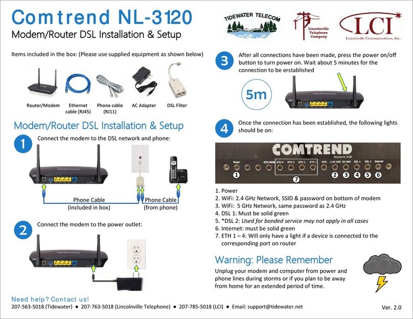
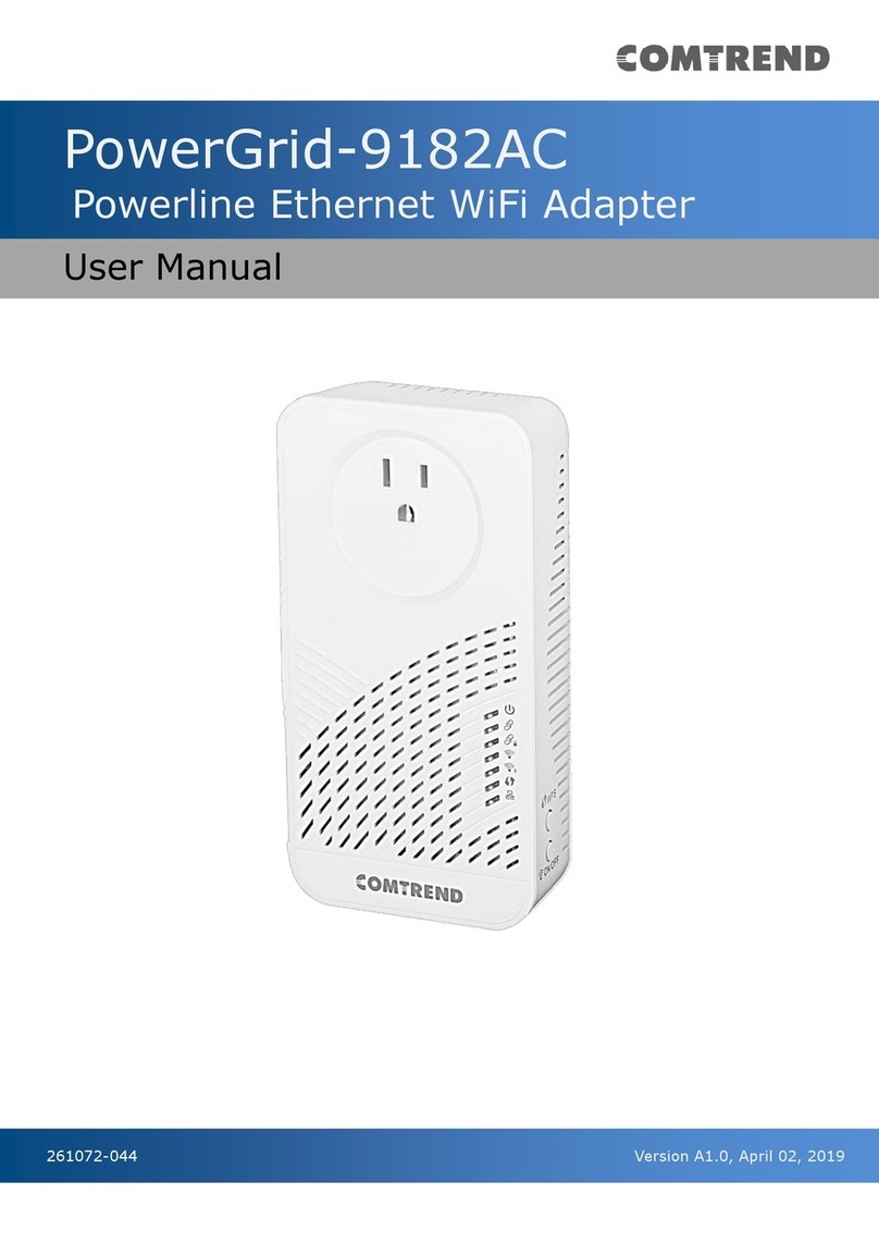
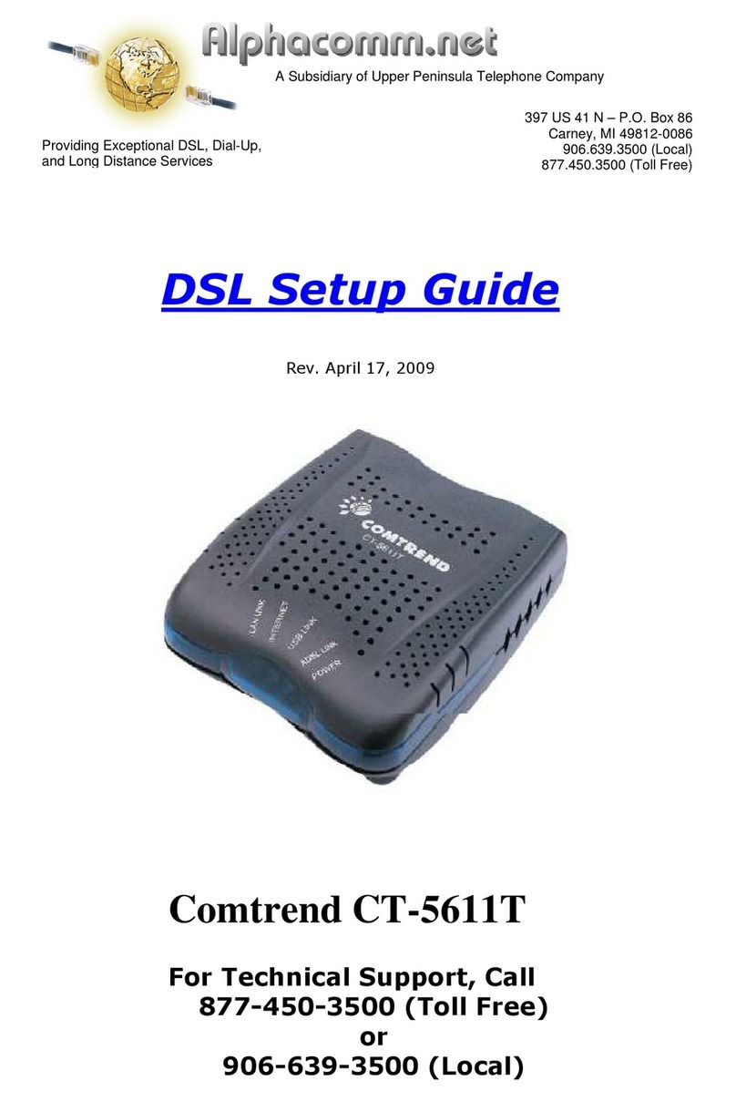
Other Comtrend Corporation Modem manuals

Comtrend Corporation
Comtrend Corporation NL-3120 Manual

Comtrend Corporation
Comtrend Corporation CT-5611T User manual

Comtrend Corporation
Comtrend Corporation NexusLink 3120 Instruction Manual

Comtrend Corporation
Comtrend Corporation CT-5072T User manual

Comtrend Corporation
Comtrend Corporation PowerGrid-9182AC User manual

Comtrend Corporation
Comtrend Corporation PG-9172AC User manual

Comtrend Corporation
Comtrend Corporation VI-3234u User manual