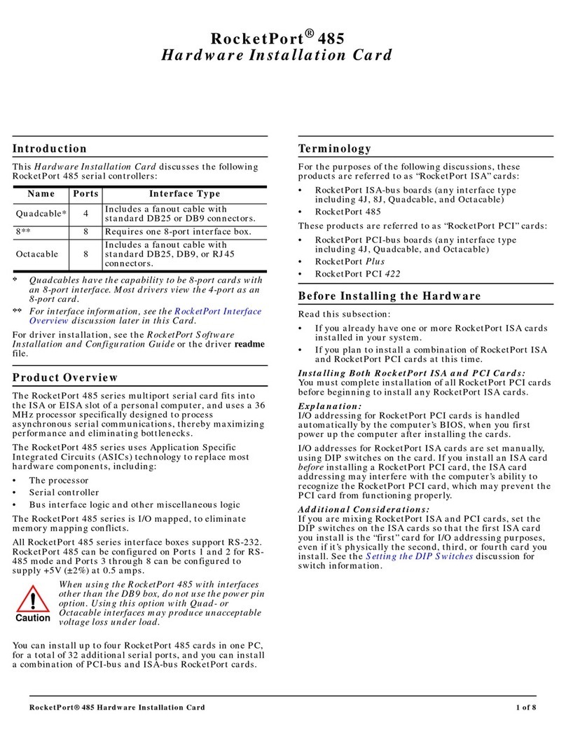
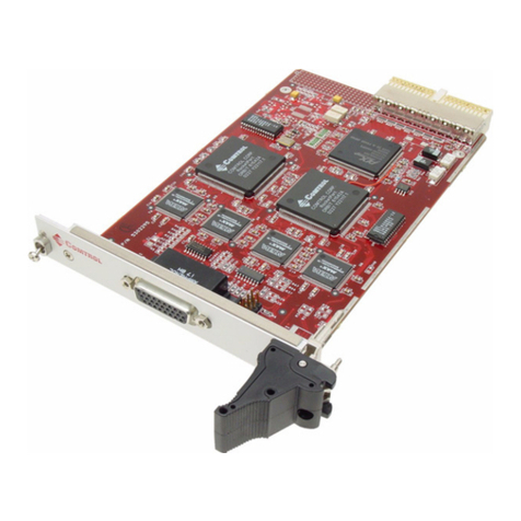
Comtrol RocketPort 485 Manual

RocketPort® 485 Hardware Installation 1 of 8
Introduction
This Hardware Installation document discusses the
following information:
•Product overview
•RocketPort terminology
•Before installing the hardware
•Installing the hardware
•Supplying power to external devices
•Interface overview
•Interface connectors and building loopback plugs
-DB9
-DB25
-RJ45
•Setting ISA DIP switches
•Hardware specifications
•FCC notices
•Troubleshooting and creating diagnostics
•Contacting Technical Support
Product Overview
The RocketPort 485 series multiport serial card fits into
the ISA or EISA slot of a personal computer, and uses a 36
MHz processor specifically designed to process
asynchronous serial communications.
The RocketPort 485 series uses Application Specific
Integrated Circuits (ASICs) technology to replace most
hardware components, including:
•The processor
•Serial controller
•Bus interface logic and other miscellaneous logic
To eliminate memory mapping conflicts, the RocketPort
485 series is I/O mapped.
This Hardware Installation document discusses the
following RocketPort 485 serial controllers:
*Quadcables have the capability to be 8-port cards with
an 8-port interface. Most drivers view the 4-port as an
8-port card.
** For interface information, see the RocketPort Interface
Overview discussion later in this Card.
All RocketPort 485 series interface boxes support RS-232.
RocketPort 485 can be configured on Ports 1 and 2 for RS-
485 mode and Ports 3 through 8 can be configured to
supply +5V (±2%) at 0.5 amps.
Caution When using the RocketPort 485 with interfaces
other than the DB9 box, do not use the power pin
option. Using this option with Quad- or
Octacable interfaces may produce unacceptable
voltage loss under load.
You can install up to four RocketPort 485 cards in one PC,
for a total of 32 additional serial ports, and you can install
a combination of PCI-bus and ISA-bus RocketPort cards.
For driver installation, see the software installation and
configuration documentation or the driver readme file for
your operating system.
RocketPort Terminology
For the purposes of the following discussions, these
products are referred to as “RocketPort ISA” cards:
•RocketPort ISA-bus boards (any interface type
including 4J, 8J, Quadcable, and Octacable)
•RocketPort 485
These products are referred to as “RocketPort PCI” cards:
•RocketPort PCI-bus boards (any interface type
including 4J, Quadcable, and Octacable)
•RocketPort Plus
•RocketPort PCI 422
Name Ports Interface Type
Quadcable* 4Includes a fanout cable with
standard DB25 or DB9 connectors.
8** 8Requires one 8-port interface box.
Octacable 8Includes a fanout cable with
standard DB25, DB9, or RJ45
connectors.
RocketPort® 485
Hardware Installation

RocketPort® 485 Hardware Installation 2 of 8
Before Installing the Hardware
Read this subsection:
•If you already have one or more RocketPort ISA cards
installed in your system.
•If you plan to install a combination of RocketPort ISA
and RocketPort PCI cards at this time.
Installing Both RocketPort ISA and PCI Cards:
You must complete installation of all RocketPort PCI cards
before beginning to install any RocketPort ISA cards.
Explanation:
I/O addressing for RocketPort PCI cards is handled
automatically by the computer’s BIOS when you first
power up the computer after installing the cards.
I/O addresses for RocketPort ISA cards are set manually
using DIP switches on the card. If you install an ISA card
before installing a RocketPort PCI card, the ISA card
addressing may interfere with the computer’s ability to
recognize the RocketPort PCI card which may prevent the
PCI card from functioning properly.
Additional Considerations:
If you are mixing RocketPort ISA and PCI cards, set the
DIP switches on the ISA cards so that the first ISA card
you install is the “first” card for I/O addressing purposes,
even if it is physically the second, third, or fourth card that
you install. See the Setting the DIP Switches discussion for
switch information.
Supplying Power to External Devices
The power connector on the RocketPort 485 card is a
standard hard drive-type power connector. You can use
this connector to provide voltage to peripheral devices on
Ports 3 through 8.
To use the power option, connect the jumpers before
installing the card. See the Installing the RocketPort
Hardware discussion for configuring this feature.
Note: Ports 3 through 8 are equipped with fuses. If an
external device draws more than 0.5 amps, the fuse
for that port automatically breaks the circuit. The
fuse remains in the tripped condition until the short
or over current condition is corrected. At this time,
the fuse will reset and the circuit will be ready for
current to be applied again.
The pinout for this connector is shown below:
Note: Power can be supplied only through DB9 or DB25
connectors. It cannot be supplied through RJ45
connectors.
Installing the RocketPort Hardware
Hardware installation consists of:
•Configuring I/O addresses
•Configuring RS-485 mode usage on Ports 1 and 2
•Installing the card in the system
•Connecting the peripherals
Note: After installing the hardware, you must install the
device driver for your operating system.
Use the following procedure to install the card.
1. If required, change the DIP switches (default is 180
hexadecimal) on the card to the desired settings. See
the Setting the DIP Switches discussion towards the
end of this Hardware Installation document.
Note: If you are installing PCI and ISA RocketPort cards,
install the PCI cards and driver before installing
and configuring the ISA cards. See the software
installation and configuration documentation or the
driver readme file for information.
2. To use RS-485 on Ports 1 and 2, move all six pins on
the port you want to use RS-485 to the left and center
position. (When all six pins are in the center and right
positions, the port is configured for RS-232.)
Note: In addition, you must configure the ports for RS-485
operation during the driver installation. For more
information, see the Software Installation and
Configuration documentation or the readme file with
the driver.
3. To use the Power feature for Ports 3 through 8, connect
the jumper for each port.
When using this card with interfaces other than
the DB9 box, do not use the Power feature. Using
this feature with Quad/Octacable interfaces
may produce unacceptable voltage loss under
load.
4. Turn off your computer.
5. Remove the system cover.
6. Select anISA or EISA expansion slot.
NC
GND
+5V
1 2 3 4
Jumpers*
Ports 3 - 8
Power
Connector
DIP Switches
Port 1**
Port 2**
Jumpers
*The Power feature is disabled as the factory default
(jumpers NOT connected).
** Port 1 is labeled Port 0 on the card and Port 2 is
labeled Port 1 on the card. Ports 1 and 2 are set to
RS-232 as the factory default.
Caution

RocketPort® 485 Hardware Installation 3 of 8
Note: RocketPort 485 can be installed in an ISA or EISA
slot. They are available on the Comtrol Software and
Documentation CD or at the Comtrol web site ftp://
ftp.comtrol.com/rport/eisa_cfg/directory.
7. Remove the slot cover.
Note: You may want to write down the model number
and serial number of the card before
installation.
8. Insert the card into the slot, seating it securely.
9. If using the Power feature, connect a hard drive-type
power supply cord in your computer to the power
connector on the card.
When enabling the Power feature, Pin 9 (DB9) or
Pin 22 (DB25) carries +5 V (±2%) at 0.5 amp.
10. Reinstall the expansion slot retaining screw.
Note: You may want to leave the system unit cover off until
the driver is installed and running, in case you need
to experiment with DIP switch settings.
11. Attach the interface that came with your card using
the appropriate procedure:
If installing a Quad/Octacable:
a. Attach the male end of the Quadcable or Octacable
to the card.
b. Tighten the retaining screws.
Note: Quad and Octacable models support RS-232
exclusively.
c. Go to Step 12 to complete the installation.
If installing a standard interface box:
a. Attach the interface box cable to the connector on
the RocketPort card mounting bracket.
a. Attach the male end of the RocketPort cable to the
card and the female end to the connector labeled
Host on the interface box.
b. Tighten the retaining screws.
12. Connect your peripheral devices.
13. Use the software installation and configuration
documentation or device driver readme file to install
the driver to complete your installation.
Note: If installing on an EISA machine, you may need the
EISACFG files. They are available on the Comtrol
Software and Documentation CD or at the Comtrol
web site ftp://ftp.comtrol.com/rport/eisa_cfg/
directory.
RocketPort Interface Overview
The RocketPort series provides several interface options:
•Quadcable and Octacable fanout cables, which are
available with the following configurations:
-Quadcable DB25 and DB9
-Octacable DB25, DB9, and RJ45
Note: RS-485 supports up to 32 multidrop.
•Interface box
Caution
Octacable
Quadcable
DB9
DB25
Note: The RJ45 cable is not displayed.

RocketPort® 485 Hardware Installation 4 of 8
DB25 Interface Connectors
Use the following subsections for DB25 interface
connectors. The Quad- and Octacable DB25 fanouts use
DB25 male connectors.
Note: Although the RocketPort 485 card supports eight
ports, if you have a quadcable connected, you will
only have four port available for use.
DB25 Pinouts
The following table and figure illustrates the DB25
connectors:
Depending on jumper configuration, the pins carry the
following values:
*Ports 1 and 2 can be either RS-232 or RS-485, while
Ports 3 through 8 are RS-232 only. All RS-232 modem
control signals are present in RS-485 mode, but not
used.
Although the RocketPort 485 is designed to
provide +5V on Ports 3 - 8, do not use the +5V
power option with the Quad/Octacable. Using
this feature with interfaces other than the DB9
box may result in unacceptable voltage loss.
Building DB25 Female Loopback Plugs or Cables
To perform loopback
testing of DB25 ports in
RS-232 mode, obtain or
create a female DB25
connector with the
following pins wired
together:
•Pins 2 to 3
•Pins 4 to 5 to 22
•Pins 6 to 8 to 20
Note: (The connector illustrated is the standard DB25F
supplied by Comtrol for use with RS-232/422
interfaces.)
To test DB25 ports in RS-485 mode, obtain two female
DB25 connectors and create the cable shown below:
DB9 Interfaces
The interface box, the Quadcable, and the Octacable all
feature DB9 ports, labeled from 1 to 8,which correspond to
the jumpers on the card.
Note: Although the RocketPort 485 card supports eight
ports, if you have a quadcable connected, you will
only have four port available for use.
DB9 Pinouts
Each connector is a DB9 male, with pins numbered as
shown below:
Depending on jumper configuration, the pins carry the
following values:
Pin RS-232 Signal RS-485 Signal
1Not used Not used
2TxD TRX+
3RxD TRX-
4RTS Not used*
5CTS Not used*
6DSR Not used*
7Signal ground Signal ground
8DCD Not used*
9-19 Not used Not used
20 DTR Not used*
21 Not used Not used
22 See Caution below
23-25 Not used Not used
Pin 14 Pin 25
Pin 1 Pin 13
Caution Pin RS-232 Signal RS-485 Signal
1CD Not used*
2RxDTRX-
3TxDTRX+
4DTR Not used*
5Signal ground Signal ground
6DSR Not used*
7RTS Not used*
8CTS Not used*
9 ** **
Pin 13Pin 1
RS-232 Only (Back View)
Pin 25Pin 14
Pin 13Pin 1
Pin 14 Pin 25
RS-485 (Back View)
Pin 13Pin 1
Pin 14 Pin 25
Pin 2 (TRX+) Pin 3 (TRX-)
Pin 1 Pin 5
Pin 6 Pin 9

RocketPort® 485 Hardware Installation 5 of 8
*Ports 1 and 2 can be either RS-232 or RS-485, while
Ports 3 through 8 are RS-232 only. All RS-232 control
signals are present in RS-485 mode, but not used.
** Ports 3 - 8 can be configured to carry +5V on Pin 9.
Do not use the +5V Power feature with the
Quad/Octacable Using Power feature with
interfaces other than the DB9 box may result in
unacceptable voltage loss.
Building DB9 Female Loopback Plugs or Cables
To perform loopback testing of DB9
ports in RS-232 mode, obtain or
create a female DB9 connector with
the following pins wired together:
•Pins 2 to 3
•Pins 7 to 8 to 9
•Pins 1 to 4 to 6
Note: If you use the +5V Power feature, either remove the
jumper or disconnect the power supply cable before
running the diagnostics. If you do not do so, the
diagnostics fail.
To test DB9 ports in RS-485 mode, obtain two female DB9
connectors and create a cable with the following wiring:
RJ45 Interfaces
The Octacable RJ45 fanouts use RJ45 connectors.
RJ45 Pinouts
The RocketPort 485 uses RJ45 connectors with the pins
numbered as shown below:
Depending on jumper configuration, the pins carry the
following values:
*Ports 1 and 2 can be either RS-232 or RS-485, while
Ports 3 through 8 are RS-232 only. All RS-232 modem
control signals are present in RS-485 mode, but not
used.
While the RocketPort 485 card can be configured
to supply +5V, this voltage is not accessible on
the RJ45 connector. Therefore this option should
not be used with the Octacable RJ45.
Building RJ45 Loopback Plugs or Cables
To perform loopback testing of RJ45
ports in RS-232 mode, obtain or
create an RJ45 connector with the
following pins wired together:
•Pins 4 to 5
•Pins 1 to 8
•Pins 2 to 6 to 7
To test RJ45 ports in RS-485 mode,
obtain two RJ45 connectors and
create the cable shown below:
Caution
Pin 1 Pin 5
Pin 6 Pin 9
RS-232 (Back View)
Pin 1 Pin 5
Pin 6 Pin 9
Pin 1 Pin 5
Pin 6 Pin 9
Pin 2 (TRX-)
Pin 3 (TRX+)
RS-485 (Back View)
Pin 1
Receptacle
1 8
RJ45 Plug
Top View
Cable
Pin 1
Pin RS-232 Signal RS-485 Signal
1RTS Not used*
2DTR Not used*
3Signal ground Signal ground
4TxD TRX+
5RxD TRX-
6DCD Not used*
7DSR Not used*
8CTS Not used*
Caution
1 8
Plug
Top View
Cable
RS-232
1 8
Plug
Top View
Cable
1 8
Plug
Top View
Cable
Pin 5 (TRX-)
Pin 4 (TRX+)
RS-485

RocketPort® 485 Hardware Installation 6 of 8
Setting the DIP Switches
The RocketPort ISA card uses a DIP switch to set the base
I/O address range. The default value is 180 (hex). If you
are installing more than one RocketPort card, or if you
experience an I/O address conflict with another device, use
the DIP switches to change the I/O address.
For example, if you install two RocketPort cards and are
using the default address range:
The following table lists possible DIP switch settings. We
recommend starting with the default settings and making
changes only if the default values produce conflicts.
Notes:
1. If installing a single RocketPort ISA card, set the DIP
switches as shown in the table.
2. If installing two ISA cards, set the DIP switches on the
second card the same as the switches on the first card,
EXCEPT SWITCH 5 OFF.
3. If installing three ISA cards, follow Note 2 for the second
card, then set the DIP switches on the third card the
same as the switches on the first card, EXCEPT
SWITCH 6 OFF.
4. If installing four ISA cards, follow Notes 2 and 3 for the
second and third cards, then set the DIP switches on the
fourth card the same as on the first card, EXCEPT
SWITCHES 5 AND 6 OFF.
Specifications
The following tables illustrate RocketPort conditions and
specifications.
Sample DIP Switch Settings
1st RocketPort
180 (hex)
2nd RocketPort
(Software address can be
any unused I/O address)
First ISA Card DIP Switch Settings (see Notes)
100 - 143 hex 140 - 183 hex
180 - 1C3 hex
200 - 243 hex 240 - 283 hex 280 - 2C3 hex
300 - 343 hex 340 - 383 hex 380 - 3C3 hex
1st Card
87654321
ON
2nd Card
87654321
ON
1
2
3
4
5
6
7
8
ON
1
2
3
4
5
6
7
8
ON
1
2
3
4
5
6
7
8
ON
1
2
3
4
5
6
7
8
ON
1
2
3
4
5
6
7
8
ON
12345678
ON
1
2
3
4
5
6
7
8
ON
1
2
3
4
5
6
7
8
ON
1
2
3
4
5
6
7
8
ON
Environmental Condition Value
Air temperature:
System on
System off 0 to 40oC
-20 to 85oC
Humidity (non-condensing):
System on
System off 8% to 80%
20% to 80%
Altitude 0 to 10,000 feet
Electromagnetic Compliance Status
Emission:
Canadian EMC requirements
CISPR-22/EN55022 Class A
FCC PART 15: Class A
Yes
Immunity:
EN50082: 801-2 ESD, 801-3 RF,
801-4 FT Yes
UL Recognized Yes
RocketPort 485 Card Specification
Baud Rate: 50 to 460.8K bps
Note: Baud rate is dependent upon hardware and
operating system configuration.
Bus interface ISA
Note: EISA files are on the Diagnostics diskette.
Control by device driver:
Data bits
Parity
Stop bits
7 or 8
Odd, Even, None
1 or 2
Current Consumption
(Values do not include
the power supplied to
external devices on
Ports 3 through 8.)
+5V +12V -12V
350 mA 110 mA 160 mA
Dimensions 6.25” by 4.2”
Heat output 16.6 BTU/Hr
Interfaces:
All models
With optional RS-485
feature enabled on
Ports 1 and 2
RS-232
RS-485
Interrupt (software
selectable)None, 3, 4, 5, 9, 10, 11, 12, 15
Mean time between
failures (MTBF) 20.5 Years
Power consumption 4.87 W

RocketPort® 485 Hardware Installation 7 of 8
FCC Notices
Radio Frequency Interference (RFI) (FCC 15.105)
This equipment has been tested and found to comply with the
limits for Class Adigital devices pursuant to Part 15 of the FCC
Rules.
This equipment generates, uses, and can radiate radio frequency
energy, and if not installed and used in accordance with the
instruction manual, may cause harmful interference to radio
communications. However, there is no guarantee that
interference will not occur in a particular installation. If this
equipment does cause harmful interference to radio or television
reception, which can be determined by turning the equipment off
and on, the user is encouraged to try and correct the interference
by one or more of the following measures:
•Reorient or relocate the receiving antenna.
•Increase the separation between the equipment and the
receiver.
•Connect the equipment to an outlet on a circuit different
from that to which the receiver is connected.
•Consult the dealer or an experienced radio/TV technician for
help.
Labeling Requirements (FCC 15.19)
This equipment complies with Part 15 of FCC Rules. Operation is
subject to the following two conditions:
•This device may not cause harmful interference, and
•This device must accept any interference received, including
interference that may cause undesired operation.
Modifications (FCC 15.21)
Changes or modifications to this equipment not expressly
approved by Comtrol Corporation may void the user’s authority to
operate this equipment.
Serial Cables (FCC 15.27)
This equipment is certified for Class Aoperation when used with
shielded cables.
Troubleshooting and Running Diagnostics
The first step to troubleshooting a problem is to determine
that your RocketPort is functioning properly. To do so, you
can create a bootable diskette.
You need two files to create a bootable floppy diagnostic
diskette:
•The Rawrite utility that creates a bootable diagnostics
diskette
•The diskette image file (*.i).
You can find both files on the Comtrol Software and
Documentation CD or download them from the ftp site.
Note: If you have the Comtrol Software and
Documentation CD, you can use the Quick Start
Card for procedures for your operating system.
Creating a Bootable Diagnostics Diskette
This discussion outlines how to create a bootable
diagnostics diskette. You can use this file on our web site
to:
•Download the necessary files.
•Easily find specific procedures for your operating
system to create the bootable diskette.
Diagnostics Overview
After you create a bootable diagnostic diskette, you can use
the diagnostic program to:
•Confirm that the hardware is functioning.
•Determine resolutions to conflicts during installation.
•Provide you with the ability to stress test the cards.
For example, you may want to run the diagnostics
overnight to evaluate a possible problem. You will need
loopback plugs for each port that you want to stress test. If
you need additional loopback plugs, you can use the
appropriate Building Loopback Plugs discussion in this
document to build additional loopback plugs.
Running the Diagnostics
You can run the diagnostics using one of the following
methods:
•Execute the rocket.exe file on the diskette in a native
DOS environment.
Note: The diagnostic occasionally fails when running in
Windows MS-DOS(R) windows.
•Boot the system from diagnostics diskette you created.
Use the following procedure to run the diagnostics:
1. Restart your machine in DOS mode or insert the
diagnostics diskette.
2. Execute rocket.exe or start the machine.
The diagnostic starts automatically,
3. Enter the appropriate letter for the base I/O range and
IRQ used for the first card.
RocketPort cards/system 4
Surge protection
with standard interface
box
Provides ESD surge
protection exceeding 10 KV.
Interface Box
Type Mounting
Dimensions Overall
Dimensions
RS-232/485,
8-Port 3.37” x 2.69” 3.68” x 3.6” x 1.6”
RocketPort 485 Card Specification

RocketPort® 485 Hardware Installation 8 of 8
Note: Only the first card requires that the I/O address
matches the physical DIP switch setting. For
each subsequent card, select any unused I/O
address available in your system.
4. Follow the remainder of the on-line instructions.
If the diagnostics did not pass you may want to use the
following discussion to diagnose your problem.
Resolving Failures
If the diagnostics could not find the card:
•Make sure that you have entered the correct I/O base
address and IRQ.
•Select a different unused I/O address (also reset the
DIP switch to the new selection).
•Turn off the power and reseat the card into the slot.
•Check for proper cable connections.
•Check for proper installation of the loopback plug.
Try running the diagnostics again. If they fail again, you
may have a bad port. Contact Technical Support.
Technical Support
Comtrol has a staff of support technicians available to help
you. Before you call, please have the following information
available:
Second Edition, January 10, 2000
Copyright © 1999, 2000 Comtrol Corporation
All Rights Reserved.
RocketPort is a registered trademark of the Comtrol
Corporation. Other product and company names
mentioned herein may be the trademarks of their
respective owners.
Comtrol Corporation makes no representations or
warranties with regard to the contents of this reference
card or to the suitability of any Comtrol product for any
particular purpose. Specifications subject to change
without notice. Some software or features may not be
available at the time of publication. Contact your reseller
for current product information.
2000048 Rev. B
Item Your System Information
Model number
Serial number
Interface type
I/O address and IRQ
Operating system
type and release
Device driver version
PC make, model, and
speed
List other devices in
the PC and their
addresses
Comtrol Headquarters Europe
Phone (612) 494-4100 +44 (0)1869 323220
FAX (612) 494-4199 +44 (0)1869 323211
Web
support Searchable Solution Database and FAQs
Web site www.comtrol.com www.comtrol.co.uk
FTP site ftp.comtrol.com
Table of contents
Other Comtrol PCI Card manuals

Comtrol
Comtrol RocketPort User manual

Comtrol
Comtrol RocketPort EXPRESS User manual

Comtrol
Comtrol RocketPort 550 Series User manual

Comtrol
Comtrol RocketPort 485 Series Parts list manual

Comtrol
Comtrol RocketPort PCI Series Manual

Comtrol
Comtrol RocketPort uPCI Plus 422 Series User manual

Comtrol
Comtrol RocketPort CompactPCI Manual