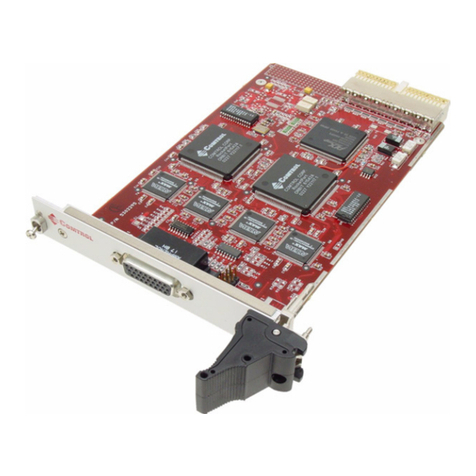
Comtrol RocketPort EXPRESS User manual

User Guide

Trademark Notices
Comtrol and RocketPort are trademarks of Comtrol Corporation.
Windows and Microsoft are registered trademarks of Microsoft Corporation.
Other product names mentioned herein may be trademarks and/or registered trademarks of their respective
owners.
Seventh Edition (Rev G), October 31, 2018
Copyright © 2007 - 2018. Comtrol Corporation.
All Rights Reserved.
Comtrol Corporation makes no representations or warranties with regard to the contents of this document or
to the suitability of the Comtrol product for any particular purpose. Specifications subject to change without
notice. Some software or features may not be available at the time of publication. Contact your reseller for
current product information.
Document Number: 2000481 Rev. G

RocketPort EXPRESS User Guide: 2000481 Rev. G Table of Contents - iii
Table of Contents
Overview...................................................................................................................................5
Product Overview.......................................................................................................................................... 5
Before Installing the RocketPort EXPRESS ........................................................................................... 5
Locating the Latest Drivers and Documentation .................................................................................. 5
Card and Interface Installation ..........................................................................................7
Installing the Card ........................................................................................................................................ 7
Attaching a Quad/Octacable Interface Cable ......................................................................................... 8
Attaching an Interface Box ......................................................................................................................... 9
Installing a Rackmount Interface Box ................................................................................................... 10
Connecting Serial Devices .................................................................................................11
DTE Versus DCE .......................................................................................................................................... 11
DB9 Serial Cables and Loopback Plugs ................................................................................................. 11
DB9 Signals............................................................................................................................................... 12
DB9 Null-Modem Cables (RS-232) .......................................................................................................... 12
DB9 Null-Modem Cables (RS-422 or RS-485 Full-Duplex) .................................................................... 12
DB9 Straight-Through Cables (RS-232 or RS-485 Half-Duplex)........................................................... 13
DB9 Loopback Plugs................................................................................................................................. 13
DB25 Serial Cables and Loopback Plugs ............................................................................................... 14
Fan-out Cable Signals .............................................................................................................................. 14
Interface Box Signals................................................................................................................................ 15
DB25 Null-Modem Cables (RS-232) ........................................................................................................ 15
DB25 Null-Modem Cables (RS-422 or RS-485 Full-Duplex) .................................................................. 16
DB25 Straight-Through Cables (RS-232 or RS-485 Half-Duplex) ......................................................... 16
DB25M: Fan-out Cable Loopback Plugs.................................................................................................. 16
DB25F: Standard Interface Box............................................................................................................... 16
DB25M: Surge Interface Box Loopback Plugs ........................................................................................ 17
RJ45 Serial Cables and Loopback Plugs................................................................................................ 17
RJ45 Signals ............................................................................................................................................. 17
RJ45 Null-Modem Cable (RS-232)........................................................................................................... 18
RJ45 Null-Modem Cable (RS-422 or RS-485 Full-Duplex) .................................................................... 18
RJ45 Straight-Through Cable (RS-232 or RS-485 Half-Duplex) ........................................................... 18
RJ45 Loopback Plugs................................................................................................................................ 18
RJ11 Serial Cables and Loopback Plugs................................................................................................ 19
RJ11 Signals ............................................................................................................................................. 19
RJ11 Null-Modem Cable (RS-232)........................................................................................................... 19
RJ11 Null-Modem Cable (RS-422 or RS-485 Full-Duplex) .................................................................... 19
RJ11 Straight-Through Cable (RS-232 or RS-485 Half-Duplex) ........................................................... 20
RJ11 Loopback Plugs................................................................................................................................ 20
Building Interfaces ..............................................................................................................21
68-Pin VHDCI Connector (Quad/Octacable).......................................................................................... 21
LFH60 and DB37M Multiplex Connectors DB9 and DB25 Interface Box Cable ........................... 23


iv - Table of Contents RocketPort EXPRESS User Guide: 2000481 Rev. G
Table of Contents
Troubleshooting ...................................................................................................................25
Before Calling Technical Support ........................................................................................................... 25
RocketPort EXPRESS Diagnostics .......................................................................................................... 25
Running the Bootable Diagnostic ............................................................................................................ 26
Testing a Port or Ports....................................................................................................................... 26
Stress Testing the RocketPort EXPRESS......................................................................................... 26
Exiting the Diagnostic ....................................................................................................................... 26
If the Diagnostic Fails........................................................................................................................ 26
Troubleshooting Windows Systems......................................................................................................... 27
Comtrol Utility.......................................................................................................................................... 27
Using PortMon to Test the Driver Installation ................................................................................ 29
Using Test Terminal to Test a Port................................................................................................... 32
Troubleshooting Linux Systems .............................................................................................................. 34
lcom(1) ....................................................................................................................................................... 34
File Transfer ............................................................................................................................................. 34
Changing Serial Port Settings (stty) ....................................................................................................... 34
Setting Up Terminals and Modems (mgetty, getty) ............................................................................... 34
Testing with minicom ............................................................................................................................... 34
Technical Support ....................................................................................................................................... 35

RocketPort EXPRESS User Guide: 2000481 Rev. G Overview - 5
Overview
Product Overview
The RocketPort EXPRESS is a high-speed in-server serial expansion card that is
RS-232/422/485 software-selectable for use in a PCI-Express (PCIe) compatible
slot in a host system. The RocketPort EXPRESS was designed to support speeds
up to 921Kbps (if connected, using fan-out cables or the 4J/8J models) or
460.8Kbps (if using an interface box).
The RocketPort EXPRESS series uses Comtrol Application Specific Integrated
Circuit (ASIC) technology to replace most hardware functionality to minimize
components, including:
• The processor
• A serial controller
• Bus interface logic and other miscellaneous logic
You can install up to four RocketPort EXPRESS cards in one computer, providing a
maximum of 128 additional serial ports.
Before Installing the RocketPort EXPRESS
If you are planning on installing the RocketPort EXPRESS in a Windows system
make sure that you have placed the device driver assembly to a location that is
available to the host system before installing the card in the host.
You can use the links in the following table to locate the latest device drivers and
documentation.
You may want to record the model and serial number of the RocketPort EXPRESS
before installing the card in the event you need to call technical support.
Locating the Latest Drivers and Documentation
This table contains links the software and installation documentation.
Software or
Document Location
Device drivers http://downloads.comtrol.com/html/rp_express_drivers.htm
Diagnostic and
Utilities http://downloads.comtrol.com/html/rp_express_diag.htm
User Guides http://downloads.comtrol.com/html/rp_express_docs.htm

6 - Overview RocketPort EXPRESS User Guide: 2000481 Rev. G
Locating the Latest Drivers and Documentation

RocketPort EXPRESS User Guide: 2000481 Rev. G Card and Interface Installation - 7
Card and Interface Installation
This section discusses the following:
•Installing the Card
•Attaching a Quad/Octacable Interface Cable on Page 8
•Attaching an Interface Box on Page 9
•Installing a Rackmount Interface Box on Page 10
Installing the Card
Use the following procedure to install a RocketPort EXPRESS card.
1. Turn off the host computer.
2. Remove the system cover from your computer.
3. Select a PCI-Express (PCIe) compatible slot.
4. Remove the slot cover or release the clamp.
5. Insert the card into the slot and seat it securely.
6. Reinstall the expansion slot retaining screw or clamp.
Do not connect an interface to the card when the host
system is powered on, this can cause the card to fail.
7. If this is not a 4J or 8J (RJ45/11 connector integrated in the card bracket),
attach the interface that came with your card using the appropriate
procedure:
•Attaching a Quad/Octacable Interface Cable on Page 8
•Attaching an Interface Box on Page 9
•Installing a Rackmount Interface Box on Page 10
8. If this is a 4J or 8J installation, see Connecting Serial Devices on Page 11 for
cabling information after driver installation.
a. Tighten the retaining screws.
b. Replace the system cover on your computer.
c. Power on your host system.
d. Click Cancel if a Found New Hardware message appears on a Windows
operating system.
Execute the device driver assembly to start the driver installation. For
other operating system device drivers, see Locating the Latest Drivers
and Documentation on Page 5.
e. After installing the device driver, you should verify that the ports are
functioning properly and then connect your serial devices. You can use the
Troubleshooting section on Page 25 for port testing procedures for your
operating system. Refer to Connecting Serial Devices on Page 11 for
information about connecting serial devices.
Caution

8 - Card and Interface Installation RocketPort EXPRESS User Guide: 2000481 Rev. G
Attaching a Quad/Octacable Interface Cable
Use this procedure to complete the quadcable or octacable installation.
1. Make sure that the host system is powered off before connecting the cable.
2. Attach the 68-pin end of the quadcable or octacable to the card.
Make sure that the
connectors are properly
aligned and forcefully push
the connector of the Quad/
Octacable with a rocking
motion into the card
connector. Make sure that
the connector is seated
tightly before tightening the
retaining screws on the
connector.
3. Tighten the retaining screws.
4. Power on the host system.
5. Click Cancel if a Found New Hardware message appears on a Windows
operating system.
Execute the device driver assembly to start the driver installation.
For other operating system device drivers, see Locating the Latest Drivers and
Documentation on Page 5.
6. After installing the driver, you should verify that the ports are functioning
properly and then connect your serial devices.
You can use the Troubleshooting section on Page 25 for port testing
procedures.
Refer to Connecting Serial Devices on Page 11 for information about
connecting serial devices.
Octacable
Quadcable
DB9
DB25
Caution

RocketPort EXPRESS User Guide: 2000481 Rev. G Card and Interface Installation - 9
Attaching an Interface Box
Use this procedure to complete the installation with an interface box.
Do not connect the cable to the RocketPort EXPRESS
card or interface box when the computer is powered
on. The interface is not hot-swappable.
Connecting the cable to the RocketPort EXPRESS
card or interface box while the computer is powered
on may damage the electronics on the card or
interface box.
1. Make sure that the host system is powered off before
connecting the cable.
2. Attach the LFH60 end of the interface cable to the
RocketPort EXPRESS card and the DB37 end to the
connector the interface box.
Make sure that the connectors are properly aligned. Do NOT use force
when connecting the cables to the host adapter card.
Note: The 32-port card uses a Y-cable that is labeled 1-16 and 17-32 on the
connectors.
3. Tighten the retaining screws.
4. Power on the host system.
5. Click Cancel if a Found New Hardware message appears on a Windows
operating system.
Execute the device driver assembly to start the driver installation.
For other operating system device drivers, see Locating the Latest Drivers and
Documentation on Page 5.
6. After installing the driver, you should verify that the ports are functioning
properly and then connect your serial devices.
You can use the Troubleshooting section on Page 25 for port testing
procedures.
Refer to Connecting Serial Devices on Page 11 for information about
connecting serial devices.
Caution
DB37
LFH60
Caution

10 - Card and Interface Installation RocketPort EXPRESS User Guide: 2000481 Rev. G
Installing a Rackmount Interface Box
Rackmount interface boxes are sturdy enough to allow you to stack several units
on a shelf, or you can mount it directly into a rack.
Do not connect the cable to the RocketPort EXPRESS card or interface
box when the computer is powered on. The interface is not hot-
swappable.
Connecting the cable to the RocketPort EXPRESS card or interface box
while the computer is powered on may damage the electronics on the
card or interface box.
1. Make sure that the host system is powered off before connecting the cable.
2. Place the Rackmount interface box on a stable surface or attach the brackets
to the interface box using the screws supplied with the unit and attach the
bracket into your rack.
3. Attach the cable shipped with the card between the interface box and the card.
Make sure that the connectors are properly aligned. Do NOT use force
when connecting the cables to the host adapter card.
Do not connect 16-port cards located in various machines to the 32-
port Rackmount. It is possible to damage the interface box and card if
the interface box is connected to two PCs using separate line power
sources.
4. Power on the host system.
5. Click Cancel if a Found New Hardware message appears on a Windows
operating system.
Execute the device driver assembly to start the driver installation.
For other operating system device drivers, see Locating the Latest Drivers and
Documentation on Page 5.
6. After installing the driver, you should verify that the ports are functioning
properly and then connect your serial devices.
You can use the Troubleshooting section on Page 25 for port testing
procedures.
Refer to Connecting Serial Devices on Page 11 for information about
connecting serial devices.
The receive LED is lit if connected to an RS-232/422/485 device.
The transmit LED is illuminated when RS-232/422/485 data is being
transmitted. Noticeable flashing occurs only if transmit data starts and stops
a few times per second or less. Otherwise, if data is being transmitted
continuously, the LED illumination appears to be constant. If no data is
transmitted the LED is off.
Caution
Caution
Rx Tx Each port has transmit and receive LEDs.

RocketPort EXPRESS User Guide: 2000481 Rev. G Connecting Serial Devices - 11
Connecting Serial Devices
This section provides information about the RocketPort EXPRESS connectors, in
the event that you need to build cables or loopback plugs.
•DB9 Serial Cables and Loopback Plugs on Page 11
•DB25 Serial Cables and Loopback Plugs on Page 14
•RJ45 Serial Cables and Loopback Plugs on Page 17
•RJ11 Serial Cables and Loopback Plugs on Page 19
A loopback plug is a serial port plug with pins wired together that you can use
with an application (for example, the diagnostic, Test Terminal, or minicom) to
test serial ports. See Before Calling Technical Support on Page 25 for information
about using the test application shipped with the RocketPort EXPRESS.
DTE Versus DCE
Most devices, except modems, are Data Terminal Equipment (DTE) devices.
Modems are Data Communication Equipment (DCE) devices. RocketPort
EXPRESS ports are configured as DTE.
How you build a cable depends on which device your are connecting to (DTE or
DCE). For example, you need a null-modem cable to connect the COM ports
(COM1 or COM2) on the computer or the RocketPort EXPRESS ports to printers,
terminals, bar code readers or DNC equipment. If you are connecting a DTE
device to a DCE device you need a straight-through modem cable.
• Straight-through cable (DTE to DCE) - connects TxD to TxD and RxD to RxD.
• Null-modem cable (DTE to DTE) - connects TxD to RxD and RxD to TxD.
DB9 Serial Cables and Loopback Plugs
The following figures and table illustrate the signals present on DB9 connectors if
you need to build your own null-modem or straight-through DB9 serial cables.
Quadcable, octacable, and the interface boxes use DB9 male connectors.
•DB9 Signals on Page 12
•DB9 Null-Modem Cables (RS-232) on Page 12
•DB9 Null-Modem Cables (RS-422 or RS-485 Full-Duplex) on Page 12
•DB9 Straight-Through Cables (RS-232 or RS-485 Half-Duplex) on Page 13
•DB9 Loopback Plugs on Page 13

12 - Connecting Serial Devices RocketPort EXPRESS User Guide: 2000481 Rev. G
DB9 Signals
DB9 Signals Refer to the manufacturer’s installation documentation if you need help with the
connector pinouts or cabling for the serial device.
DB9 Null-Modem
Cables (RS-232)
Use the following figure if you need to build an RS-232 null-modem cable. A null-
modem cable is required for connecting DTE devices.
If you need RTS-CTS/DTR-DSR
hardware flow control, you can use
the pinouts provided in the
following example.
You may want to purchase or build
a straight-through cable and
purchase a null-modem adapter.
For example, a null-modem cable
can be used to connect COM2 of
one PC to COM2 of another PC.
Note: RJ45 connectors are not
standardized. Refer to your
serial device documentation
for signal information.
DB9 Null-Modem
Cables (RS-422 or
RS-485 Full-Duplex)
Use the following figure if you need to build
an RS-422 or RS-485 full-duplex null-modem
cable. A null-modem cable is required for
connecting DTE devices.
Note: RS-422 and RS-45 signals are not
standardized and each serial
manufacturer uses different pinouts.
Refer to the serial device
documentation to determine the
pinouts for the signals above.
DB9 Male Connector Signals
Pin RS-232 RS-422 RS-485
(Full-Duplex)
RS-485
(Half-Duplex)
1 DCD Not used Not used Not used
2 RxD RxD- RxD- Not used
3 TxD TxD- TxD- TRxD-
4 DTR Not used Not used Not used
5 SIG GND SIG GND SIG GND SIG GND
6 DSR Not used Not used Not used
7 RTS TxD+ TxD+ TRxD+
8CTS RxD+ RxD+Notused
9 RI Not used Not Used Not Used
Ground must be tied to signal ground.
Pin 1 Pin 5
Pin 6 Pin 9
TxD
RxD
RTS
CTS
DSR
GND
DCD
DTR
Signal
RxD
TxD
CTS
RTS
DTR
GND
DCD
DSR
Signal
DB9
2
3
8
7
4
5
1
6
Pins DB25
3
2
4
7
8
6
Pins
20
5
DB9
3
2
7
8
6
5
1
4
Pins
RI RI9229
RocketPort DTE Serial Device
TxD+
TxD-
RxD+
Signal DB9
7
3
8
Pins
RxD+
RxD-
Signal
TxD+
TxD-
RxD- 2
RocketPort DTE Serial
Device

RocketPort EXPRESS User Guide: 2000481 Rev. G Connecting Serial Devices - 13
DB9 Straight-Through Cables (RS-232 or RS-485 Half-Duplex)
DB9 Straight-
Through Cables (RS-
232 or RS-485 Half-
Duplex)
Use the following figure if
you need to build an RS-
232 or RS-485 half-duplex
straight-through cable.
Straight-through cables
are used to connect
modems and other DTE
devices. For example, a
straight-through cable can
be used to connect COM2
of one PC to a modem.
Note: RJ45 connectors are
not standardized.
Refer to your serial
device documentation for signal information.
DB9 Loopback Plugs RocketPort EXPRESS models with DB9 connectors on
the interface are shipped with a a single loopback plug
(RS-232/422).
Wire the following pins together to build additional
plugs or replace a missing RS-232/422 loopback plug.
• Pins 1 to 4 to 6
•Pins2to3
• Pins 7 to 8 to 9
Wire these pins together if you want to build an RS-422 (only) loopback plug.
•Pins2to3
•Pins7to8
DB9
1
2
3
4
5
8
6
7
Pins
DCD
RxD
TxD or TRxD-
DTR
GND
CTS
DSR
RTS or TRxD+
Signal
DB9
1
2
3
4
5
8
6
7
Pins
DCD
RxD
TxD or TRxD-
DTR
GND
CTS
DSR
RTS or TRxD+
Signal
RI 9 9RI
DB25
8
3
2
20
7
5
6
4
Pins
22
RocketPort DCE Serial Device
Pin 1 Pin 5
Pin 6 Pin 9
RS-232/422 (Back View)

14 - Connecting Serial Devices RocketPort EXPRESS User Guide: 2000481 Rev. G
DB25 Serial Cables and Loopback Plugs
This section describes DB25 cables and loopback plugs for the following models:
•Fan-out Cable Signals (quadcable and octacable)
•Interface Box Signals on Page 15 (standard and surge models)
•DB25 Null-Modem Cables (RS-232) on Page 15
•DB25 Null-Modem Cables (RS-422 or RS-485 Full-Duplex) on Page 16
•DB25 Straight-Through Cables (RS-232 or RS-485 Half-Duplex) on Page 16
•DB25M: Fan-out Cable Loopback Plugs on Page 16
•DB25F: Standard Interface Box on Page 16
•DB25M: Surge Interface Box Loopback Plugs on Page 17
Note: Refer to the manufacturer’s installation documentation if you need help
with connector pinouts or cabling for the serial device.
Fan-out Cable
Signals
Refer to the manufacturer’s installation documentation if you need help with the
connector pinouts or cabling for the serial device.
DB25 Male Connector Signals (Quad/Octacables)
Pin RS-232 RS-422 RS-485
(Full-Duplex)
RS-485
(Half-Duplex)
1 Not used Not used Not used Not used
2 TxD TxD- TxD- TRxD-
3 RxD RxD- RxD- Not used
4 RTS TxD+ TxD+ TRxD+
5 CTS RxD+ RxD+ Not used
6 DSR Not used Not used Not used
7 SIG GND SIG GND SIG GND SIG GND
8 DCD Not used Not used Not used
9 to 19 Not used Not used Not used Not used
20 DTR Not used Not used Not used
21 Not used Not used Not used Not used
22 RI Not used Not used Not used
23-25 Not used Not used Not used Not used
Ground must be tied to signal ground.
Pin 14 Pin 25
Pin 1 Pin 13

RocketPort EXPRESS User Guide: 2000481 Rev. G Connecting Serial Devices - 15
Interface Box Signals
Interface Box
Signals
Refer to the manufacturer’s installation documentation if you need help with the
connector pinouts or cabling for the serial device.
DB25 Null-Modem
Cables (RS-232)
Use the following figure if you
need to build an RS-232 null-
modem cable. A null-modem
cable is required for
connecting DTE devices.
You may want to purchase or
build a straight-through cable
and purchase a null-modem
adapter. For example, a null-
modem cable can be used to
connect COM2 of one PC to
COM2 of another PC.
Note: RJ45 connectors are not
standardized. Refer to
your serial device
documentation for
signal information.
DB25 Female (Standard Interface Box) and
DB 25 Male (Surge Interface Box)
Connector Signals
Pin RS-232 RS-422 RS-485
(Full-Duplex)
RS-485
(Half-Duplex)
1 Not used Not used Not used Not used
2 TxD TxD- TxD- TRxD-
3 RxD RxD- RxD- Not used
4 RTS TxD+ TxD+ TRxD+
5 CTS RxD+ RxD+ Not used
6 DSR Not used Not used Not used
7 SIG GND SIG GND SIG GND SIG GND
8 DCD Not used Not used Not used
15 CTS RxD+ RxD+ Not used
17 RxD RxD- RxD- Not used
19 RTS TxD+ TxD+ TRxD+
20 DTR Not used Not used Not used
21 Not used Not used Not used Not used
22 RI Not used Not used Not used
23-24 Not used Not used Not used Not used
25 TxD TxD- TxD- TRxD-
Ground must be tied to signal ground.
Pin 14 Pin 25
Pin 1 Pin 13
Male
Pin 25 Pin 14
Pin 13 Pin 1
Female
TxD*
RxD*
RTS*
CTS*
DSR
GND
DCD
DTR
Signal
RxD
TxD
CTS
RTS
DTR
GND
DCD
DSR
Signal
DB9
2
3
8
7
4
5
1
6
Pins DB25
3
2
4
7
8
6
Pins
20
5
DB25
2
3
4
5
6
7
8
20
Pins
RI RI92222
RocketPort DTE Serial Device
* Interface boxes have alternate pins available for this
signal. Refer to Interface Box Signals for additional
information.

16 - Connecting Serial Devices RocketPort EXPRESS User Guide: 2000481 Rev. G
DB25 Null-Modem Cables (RS-422 or RS-485 Full-Duplex)
DB25 Null-Modem
Cables (RS-422 or
RS-485 Full-Duplex)
Use the following figure if you need to build an
RS-422 or RS-485 full-duplex null-modem
cable. A null-modem cable is required for
connecting DTE devices.
Interface boxes have optional pins available
for these signals. Refer to Interface Box
Signals on Page 15 for more information.
Note: RS-422 and RS-485 signals are not
standardized and each serial
manufacturer uses different pinouts. Refer to the serial device
documentation to determine the pinouts for the signals above.
DB25 Straight-
Through Cables (RS-
232 or RS-485 Half-
Duplex)
Use the following figure
if you need to build an
RS-232 or RS-485 half-
duplex straight-through
cable. Straight-through
cables are used to
connect modems and
other DTE devices. For
example, a straight-
through cable can be
used to connect COM2
of one PC to a modem.
DB25M: Fan-out
Cable Loopback
Plugs
RocketPort EXPRESS models with DB25 male connectors on the interface are
shipped with a a single loopback plug (RS-232/422).
Wire the following pins together to build additional
RS-232/422 plugs or replace a missing RS-232/422
loopback plug.
•Pins2to3
• Pins 4 to 5 to 22
• Pins 6 to 8 to 20
You can wire the following pins together for an RS-422 only loopback plug.
•Pins2to3
•Pins4to5
DB25F: Standard
Interface Box
RocketPort EXPRESS models with DB25 female connectors on the interface box
are shipped with a a single loopback plug (RS-232/422).
Wire the following pins together to build additional
RS-232/422 plugs or replace a missing RS-232/422
loopback plug.
• Pins 2 to 3 or alternately, Pins 25 to 17
• Pins 4 to 5 to 22 or alternately, Pins 19 to 15 to 22
• Pins 6 to 8 to 20
You can wire the following pins together for an RS-422 only loopback plug.
• Pins 2 to 3 or alternately, Pins 17 to 25
• Pins 4 to 5 or alternately, Pins 15 to 19
TxD+
TxD-
RxD+
Signal DB25
4
2
5
Pins
RxD+
RxD-
Signal
TxD+
TxD-
RxD- 3
RocketPort DTE Serial
Device
DB9
1
2
3
4
5
8
6
7
Pins
DCD
RxD
TxD or TRxD-
DTR
GND
CTS
DSR
RTS or TRxD+
Signal
DB25
8
3
2
20
7
5
6
4
Pins
DCD
RxD*
TxD* or TRxD-
DTR
GND
CTS*
DSR
RTS* or TRxD+
Signal
RI 22 9RI
DB25
8
3
2
20
7
5
6
4
Pins
22
RocketPort DCE Serial Device
* Interface boxes have alternate pins available for this signal.
Refer to Interface Box Signals for more information.
Pin 13Pin 1
RS-232/422 (Back View)
Pin 14 Pin 25
Male
Pin 13 Pin 1
RS-232/422 (Back View)
Pin 14
Pin 25
Female

RocketPort EXPRESS User Guide: 2000481 Rev. G Connecting Serial Devices - 17
DB25M: Surge Interface Box Loopback Plugs
DB25M: Surge
Interface Box
Loopback Plugs
RocketPort EXPRESS models with DB25 male connectors on the Surge interface
box are shipped with a a single loopback plug (RS-232/422).
Wire the following pins together to build additional
RS-232/422 plugs or replace a missing RS-232/422
loopback plug.
• Pins 2 to 3 or alternately, Pins 17 to 25
• Pins 4 to 5 to 22 or alternately, Pins 15 to 19 to 22
• Pins 6 to 8 to 20
You can wire the following pins together for an RS-422 only loopback plug.
• Pins 2 to 3 or alternately, Pins 17 to 25
• Pins 4 to 5 or alternately, Pins 15 to 19
RJ45 Serial Cables and Loopback Plugs
This section describes RJ45 cables and loopback plugs for the RocketPort
EXPRESS 4J, Octacable and Rackmount interface boxes.
•RJ45 Signals
•RJ45 Null-Modem Cable (RS-232) on Page 18
•RJ45 Null-Modem Cable (RS-422 or RS-485 Full-Duplex) on Page 18
•RJ45 Straight-Through Cable (RS-232 or RS-485 Half-Duplex) on Page 18
•RJ45 Loopback Plugs on Page 18
RJ45 Signals There are no standards for RJ45 connector pinouts. Refer to the
manufacturer’s installation documentation if you need help with
connector pinouts or cabling for the serial device.
Note: Ring indicator is not supported on the RJ45 connector.
Pin 13Pin 1
RS-232/422 (Back View)
Pin 14 Pin 25
RJ45 Connector Signals
Pin RS-232 RS-422 RS-485
(Full-Duplex)
RS-485
(Half-Duplex)
1 RTS TxD+ TxD+ TRxD+
2 DTR Not Used Not Used Not Used
3 SIG GND SIG GND SIG GND SIG GND
4 TxD TxD- TxD- TRxD-
5 RxD RxD- RxD- Not Used
6 DCD Not Used Not Used Not Used
7 DSR Not Used Not Used Not Used
8 CTS RxD+ RxD+ Not Used
Ground must be tied to signal ground.

18 - Connecting Serial Devices RocketPort EXPRESS User Guide: 2000481 Rev. G
RJ45 Null-Modem Cable (RS-232)
RJ45 Null-Modem
Cable (RS-232)
Use the following figure if you need
to build an RS-232 null-modem cable.
A null-modem cable is required for
connecting DTE devices.
RJ45 Null-Modem
Cable (RS-422 or RS-
485 Full-Duplex)
Use the following figure if you need to build
an RS-422 null-modem cable. A null-modem
cable is required for connecting DTE
devices.
Note: RS-422 pinouts are not standardized.
Each serial manufacturer uses
various pinouts. Please refer to the
documentation for the serial to
determine the pinouts for the signals in the previous picture.
RJ45 Straight-
Through Cable (RS-
232 or RS-485 Half-
Duplex)
Use straight-through cables to connect modems and other DTE devices. For
example, you can connect one end of a straight-through cable to COM2 on one
computer and the other end of the straight-through cable to a modem.
RJ45 Loopback
Plugs
RocketPort EXPRESS models with RJ45 connectors are shipped with
a a single loopback plug (RS-232/422).
Wire the following pins together to build additional loopback plugs or
replace a missing RS-232/422 loopback plug:
•Pins4to5
•Pins1to8
•Pins2to6to7
Wire the following pins together for an RS-422 loopback plug:
•Pins4to5
•Pins1to8
TxD
RxD
RTS
CTS
DSR
GND
DCD
DTR
Signal
RxD
TxD
CTS
RTS
DTR
GND
DCD
DSR
Signal
DB9
2
3
8
7
4
5
1
6
Pins
DB25
3
2
4
7
8
6
Pins
RJ45
4
5
1
8
7
3
6
2
Pins
20
5
RocketPort DTE Serial Device
TxD+
TxD-
RxD+
Signal RJ45
1
4
8
Pins
RxD+
RxD-
Signal
RxD- 5
TxD+
TxD-
DTE Serial
Device
RocketPort
DB9
1
2
3
4
5
8
6
7
Pins
DCD
RxD
TxD TRxD-
DTR
GND
CTS
DSR
RTS TRxD+
Signal
DCD
RxD
TxD TRxD-
DTR
GND
CTS
DSR
RTS TRxD+
Signal
RI 9
RJ45
6
5
4
2
3
8
7
1
Pins
N/A
DB25
8
3
2
20
7
5
6
4
Pins
22 RI
RocketPort DCE Serial Device
RS-232 RS-485HD RS-232 RS-485HD
RS-232/422

RocketPort EXPRESS User Guide: 2000481 Rev. G Connecting Serial Devices - 19
RJ11 Serial Cables and Loopback Plugs
This section describes RJ11 cables and loopback plugs for the RocketPort
EXPRESS 8J.
•RJ11 Signals
•RJ11 Null-Modem Cable (RS-232) on Page 19
•RJ11 Null-Modem Cable (RS-422 or RS-485 Full-Duplex) on Page 19
•RJ11 Straight-Through Cable (RS-232 or RS-485 Half-Duplex) on Page 20
•RJ11 Loopback Plugs on Page 20
RJ11 Signals There are no standards for RJ11 connector pinouts. Refer to the
manufacturer’s installation documentation if you need help with
connector pinouts or cabling for the serial device.
Note: Ring indicator, Request to Send, and Data Set Ready are not
supported on the RJ11 connector.
RJ11 Null-Modem
Cable (RS-232)
Use the following figure if you need
to build an RS-232 null-modem
cable. A null-modem cable is
required for connecting DTE devices.
RJ11 Null-Modem
Cable (RS-422 or RS-
485 Full-Duplex)
Use the following figure if you need to build
an RS-422 null-modem cable. A null-modem
cable is required for connecting DTE devices.
Note: RS-422 pinouts are not standardized.
Each serial manufacturer uses
various pinouts. Please refer to the
documentation for the serial to
determine the pinouts for the signals
in the previous picture.
RJ11 Connector Signals
Pin RS-232 RS-422 RS-485
(Full-Duplex)
RS-485
(Half-Duplex)
1 DTR TxD+ TxD+ TRxD+
2 SIG GND SIG GND SIG GND SIG GND
3 TxD TxD- TxD- TRxD-
4 RxD RxD- RxD- Not Used
5 DCD Not Used Not Used Not Used
6 CTS RxD+ RxD+ Not Used
Ground must be tied to signal ground.
TxD
RxD
Signal
RxD
TxD
RTS
Signal
DB25
3
2
Pins
RJ11
3
4
Pins
4
RocketPort DTE Serial Device
DB9
2
3
7
Pins
CTS 6
DCD
DTR DCD
DTR
20
5
18
1
14
GND GND
7
25
RS-232
TxD+
TxD-
RxD+
Signal RJ11
1
3
6
Pins
RxD+
RxD-
Signal
RxD- 4
TxD+
TxD-
DTE Serial
Device
RocketPort
RS-422/RS-485FD

20 - Connecting Serial Devices RocketPort EXPRESS User Guide: 2000481 Rev. G
RJ11 Straight-Through Cable (RS-232 or RS-485 Half-Duplex)
RJ11 Straight-
Through Cable (RS-
232 or RS-485 Half-
Duplex)
Use straight-through cables to connect modems and DTE devices. For example,
you can connect one end of a straight-through cable to COM2 on one computer and
the other end of the straight-through cable to a modem.
RJ11 Loopback
Plugs
RocketPort EXPRESS models with RJ11 connectors are shipped with
a a single loopback plug (RS-232/422).
Wire the following pins together to build additional loopback plugs or
replace a missing RS-232/422 loopback plug:
•Pins3to4
•Pins1to6
DTR TRxD+ 1
DCD
RxD
TxD TRxD-
DTR TRxD+
GND
Signal
DCD
RxD
TxD TRxD-
GND
Signal RJ11
5
4
3
2
Pins
DB25
8
3
2
20
7
Pins
RocketPort DCE Serial Device
DB9
1
2
3
4
5
Pins
CTS
CTS 65
8
RS-232 RS-485HD RS-232 RS-485HD
Table of contents
Other Comtrol PCI Card manuals

Comtrol
Comtrol RocketPort 550 Series User manual

Comtrol
Comtrol RocketPort PCI Series Manual

Comtrol
Comtrol RocketPort 485 Manual

Comtrol
Comtrol RocketPort CompactPCI Manual

Comtrol
Comtrol RocketPort User manual

Comtrol
Comtrol RocketPort uPCI Plus 422 Series User manual

Comtrol
Comtrol RocketPort 485 Series Parts list manual
Popular PCI Card manuals by other brands

ATCOM
ATCOM AXE4DL user manual

ATI Technologies
ATI Technologies Radeon X1900G5 Getting started guide

Acces I/O products
Acces I/O products PCI-IDO-48A user manual

TerraTec
TerraTec Cinergy HT PCI Technical details

HP
HP StorageWorks fca2384 installation guide

AudioCodes
AudioCodes SmartWORKS NGX Quick install