Comtrol RocketPort uPCI Plus 422 Series User manual

User Guide

Trademark Notices
Comtrol and RocketPort are trademarks of Comtrol Corporation.
Windows and Microsoft are registered trademarks of Microsoft Corporation.
Other product names mentioned herein may be trademarks and/or registered trademarks of their respective
owners.
Second Edition (Rev B), September 12, 2011
Copyright © 2007 - 2011. Comtrol Corporation.
All Rights Reserved.
Comtrol Corporation makes no representations or warranties with regard to the contents of this document or
to the suitability of the Comtrol product for any particular purpose. Specifications subject to change without
notice. Some software or features may not be available at the time of publication. Contact your reseller for
current product information.
Document Number: 2000370 Rev. B

RocketPort uPCI Plus 422 User Guide: 2000370 Rev. B Table of Contents - 3
Table of Contents
Overview...................................................................................................................................5
Product Overview.......................................................................................................................................... 5
Supported Models.......................................................................................................................................... 5
Before Installing the RocketPort uPCI Plus 422.................................................................................... 5
Locating the Latest Drivers and Documentation .................................................................................. 6
Card and Interface Installation ..........................................................................................7
Connecting RS-422 Serial Devices......................................................................................9
DTE Versus DCE ............................................................................................................................................ 9
DB9 Serial Cables and Loopback Plugs ................................................................................................... 9
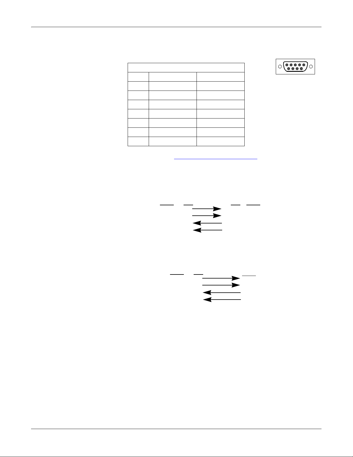
DB9 Signals (RS-422) ............................................................................................................................... 10
Straight-Through Cables (DCE) .............................................................................................................. 10
Null-Modem Cables (DTE) ....................................................................................................................... 10
DB9 Loopback Plugs................................................................................................................................. 11
Straight-Through Cables (DCE) .............................................................................................................. 11
Null-Modem Cables (DTE) ....................................................................................................................... 11
Troubleshooting ...................................................................................................................13
Before Calling Technical Support ........................................................................................................... 13
RocketPort uPCI Plus 422 Diagnostics .................................................................................................. 13
Bootable CD .............................................................................................................................................. 14
Running the Bootable Diagnostic CD ...................................................................................................... 14
Testing a Port or Ports ....................................................................................................................... 14
Stress Testing the RocketPort uPCI Plus 422 .................................................................................. 15
Exiting the Diagnostic ....................................................................................................................... 15
If the Diagnostic Fails ........................................................................................................................ 15
Troubleshooting Windows Systems......................................................................................................... 15
Comtrol Utility.......................................................................................................................................... 16
Using PortMon to Test the Driver Installation ................................................................................ 18
Using Test Terminal to Test a Port ................................................................................................... 21
Troubleshooting Linux Systems .............................................................................................................. 23
lcom(1) ....................................................................................................................................................... 23
File Transfer ............................................................................................................................................. 23
Changing Serial Port Settings (stty) ....................................................................................................... 23
Setting Up Terminals and Modems (mgetty, getty) ............................................................................... 23
Testing with minicom ............................................................................................................................... 23
Technical Support ....................................................................................................................................... 24
Index........................................................................................................................................25

4 - Table of Contents RocketPort uPCI Plus 422 User Guide: 2000370 Rev. B
Table of Contents

RocketPort uPCI Plus 422 User Guide: 2000370 Rev. B Overview - 5
Overview
Product Overview
The RocketPort uPCI Plus 422 series multiport serial card fits into the PCI slot of
a personal computer, and uses a 43 MHz processor that is specifically designed to
process asynchronous serial communications.
The RocketPort uPCI Plus 422 supports RS-422 exclusively, in either DTE or DCE
mode. It supports 3.3 and 5.0 volt PCI bus architecture and is compatible with 32-
and 64-bit PCI slots. The RocketPort uPCI Plus 422 card supports
communications speeds up to 921,600 baud.
The RocketPort uPCI Plus 422 series uses Comtrol Application Specific Integrated
Circuit (ASIC) technology to replace most hardware functionality to minimize
components, including:
• The processor
• A serial controller
• Bus interface logic and other miscellaneous logic
You can install up to four RocketPort uPCI Plus 422 cards in one computer,
providing a maximum of 32 additional serial ports. The PC must comply with the
PCI 2.2 specification or greater.
Supported Models
The RocketPort uPCI Plus 422 family consists of the following models:
• Quadcable (fanout cable) with four DB9 male connectors
• Octacable (fanout cable) with eight DB9 male connectors
Before Installing the RocketPort uPCI Plus 422
If you are planning on installing the RocketPort uPCI Plus 422 in a Windows
system make sure that you have placed the device driver assembly to a location
that is available to the host system before installing the card in the host.
You can use the Software and Documentation CD to locate the latest device drivers
and documentation. Optionally, you can use the links in the following subsection.
You may want to record the model and serial number of the RocketPort uPCI Plus
422 before installing the card in the event you need to call technical support.

6 - Overview RocketPort uPCI Plus 422 User Guide: 2000370 Rev. B
Overview
Locating the Latest Drivers and Documentation
This table contains links the software and installation documentation.
Software or
Document Location
Device drivers ftp://ftp.comtrol.com/html/RPuPCIplus422_drivers.htm
Diagnostic and
Utilities ftp://ftp.comtrol.com/html/RPuPCIplus422_diag.htm
User Guides ftp://ftp.comtrol.com/html/RPuPCIplus422_docs.htm

RocketPort uPCI Plus 422 User Guide: 2000370 Rev. B Card and Interface Installation - 7
Card and Interface Installation
Use the following procedure to install a RocketPort uPCI Plus 422 card.
1. If this is a Windows installation, copy the latest driver to your system before
installing the RocketPort uPCI Plus 422. See Locating the Latest Drivers and
Documentation on Page 6 to locate the latest driver and installation
documentation.
2. Turn off the host computer.
Note: You may want to write down the model number and serial number of
the card before installation.
3. If necessary, set the DIP switches for the appropriate communications mode.
The default DIP switch setting is DTE.
•DCE mode, if necessary, set the DIP switch to ON on the corresponding
ports.
•DTE mode, if necessary, set the DIP switch to OFF on the corresponding
ports.
4. Remove the system cover from your computer.
5. Select a PCI expansion slot.
6. Remove the slot cover or release the clamp.
7. Insert the card into the slot and seat it securely.
8. Reinstall the expansion slot retaining screw or clamp.
Note: You may want to replace the system cover after the driver is installed
and running in the event that you need to change the DTE/DCE switch
setting.
Do not connect an interface to the card when the host system is
powered on, this can cause card failure.
DIP Switch
OFF
ON
DCE = On (Down)
DTE = Off (Up)
Factory Default Setting = DTE
Caution

8 - Card and Interface Installation RocketPort uPCI Plus 422 User Guide: 2000370 Rev. B
Card and Interface Installation
9. Attach the DB78 end of the quadcable or octacable to the card.
Make sure that the connectors are properly
aligned and forcefully push the connector of
the Octacable with a rocking motion into the
card connector. Make sure that the connector
is seated tightly before tightening the
retaining screws on the connector.
10. Tighten the retaining screws on the connector.
11. Power on the host system.
12. Click Cancel if a Found New Hardware message
appears on a Windows operating system.
Execute the device driver file to start the driver installation.
For other operating system device drivers, see Locating the Latest Drivers and
Documentation on Page 6.
13. After installing the driver, you should verify that the ports are functioning
properly and then connect your serial devices.
You can use the Troubleshooting section on Page 13 for port testing procedures
for your operating system.
Refer to Connecting RS-422 Serial Devices on Page 9 for information about
connecting serial devices.
Caution
Octacable
DB9

RocketPort uPCI Plus 422 User Guide: 2000370 Rev. B Connecting RS-422 Serial Devices - 9
Connecting RS-422 Serial Devices
This section provides information about the RocketPort uPCI Plus 422 connectors,
in the event that you need to build cables or loopback plugs.
A loopback plug is a serial port plug with pins wired together that you can use
with application (for example, the diagnostic, Test Terminal, or minicom) to test
serial ports. See Before Calling Technical Support on Page 13 for information
about using the test application shipped with the RocketPort uPCI Plus 422.
DTE Versus DCE
The DIP switch for the RocketPort uPCI Plus 422 ports are set to DTE at the
factory.
Most serial devices, except modems, are Data Terminal Equipment (DTE) devices.
Modems are Data Communication Equipment (DCE) devices.
How you build a cable depends on which device your are connecting to (DTE or
DCE). For example, you need a null-modem cable to connect the COM ports
(COM1 or COM2) on the computer or the RocketPort uPCI Plus 422 ports to
printers, terminals, bar code readers or DNC equipment. If you are connecting a
DTE device to a DCE device you need a straight-through modem cable.
• Straight-through cable (DTE to DCE) - connects TxD to TxD and RxD to RxD.
• Null-modem cable (DTE to DTE) - connects TxD to RxD and RxD to TxD.
Note: DTE and DCE modes are controlled with the DIP switch on the RocketPort
uPCI Plus 422 (see Card and Interface Installation on Page 7 for
information).
DB9 Serial Cables and Loopback Plugs
The following figures and table illustrate the signals present on DB9 connectors if
you need to build your own null-modem or straight-through DB9 serial cables.
Quadcables and octacables use DB9 male connectors.
•DB9 Signals (RS-422) on Page 10
•Straight-Through Cables (DCE) on Page 10
•Null-Modem Cables (DTE) on Page 10
•DB9 Loopback Plugs on Page 11

10 - Connecting RS-422 Serial Devices RocketPort uPCI Plus 422 User Guide: 2000370 Rev. B
Connecting RS-422 Serial Devices
DB9 Signals (RS-
422)
This subsection provides DB9 signal information. Refer to the
manufacturer’s installation documentation if you need help
with the connector pinouts or cabling for the serial device.
Note: DTE and DCE mode are controlled with the DIP switch on the RocketPort
uPCI Plus 422. See Card and Interface Installation on Page 7 for
information. The factory default is set to DTE.
Straight-Through
Cables (DCE)
Use the following figure if you need to build an RS-422 straight-through cable for
DCE devices.
Null-Modem Cables
(DTE)
Use the following figure if you need to build an RS-422 null-modem cable for DTE
devices.
Note: RS-422 signals are not standardized and each serial manufacturer uses
different pinouts. Refer to the serial device documentation to determine the
pinouts for the signals above.
RS-422 DB9 Male Connector
Pins DCE Mode DTE Mode
1Not used Not used
2RxD- TxD-
3TxD+ RxD+
4-6 Not used Not used
7RxD+ TxD+
8TxD- RxD-
9Chassis Ground Chassis Ground
Pin 1 Pin 5
Pin 6 Pin 9
Male
TxD+
TxD-
RxD+
Signal
3
8
7
Pins
RxD-
RocketPort Sony DB9ConnectorDCE Mode
2
3
8
7
Pins
2
TxD+
TxD-
RxD+
Signal
RxD-
TxD+
TxD-
RxD+
Signal
7
2
3
Pins RxD+
RxD-
Signal
TxD+
TxD-
RxD- 8
DTE Serial DeviceRocketPort DTE Mode

RocketPort uPCI Plus 422 User Guide: 2000370 Rev. B Connecting RS-422 Serial Devices - 11
Connecting RS-422 Serial Devices
DB9 Loopback Plugs RocketPort uPCI Plus 422 are shipped with a a single loopback plug. You can use
loopback plugs with application software (for example, Test Terminal) to test
serial ports.
Wire the following pins together to build additional plugs or replace a missing
loopback plug.
•Pins2to8
•Pins3to7
Note: DTE and DCE mode are controlled with the DIP
switch on the RocketPort uPCI Plus 422. See Card
and Interface Installation on Page 7 for information.
The factory default is set to DTE.
Straight-Through
Cables (DCE)
Use the following figure if you need to build an RS-422 straight-through cable for
DCE devices.
Null-Modem Cables
(DTE)
Use the following figure if you need to build an RS-422 null-modem cable for DTE
devices.
Note: RS-422 signals are not standardized and each serial manufacturer uses
different pinouts. Refer to the serial device documentation to determine the
pinouts for the signals above.
RS-422 (Back View)
Pin 5Pin 1
Pin 9
Pin 6
Loopback
TxD+
TxD-
RxD+
Signal
3
8
7
Pins
RxD-
RocketPort Sony DB9 ConnectorDCE Mode
2
3
8
7
Pins
2
TxD+
TxD-
RxD+
Signal
RxD-
TxD+
TxD-
RxD+
Signal
7
2
3
Pins RxD+
RxD-
Signal
TxD+
TxD-
RxD- 8
DTE Serial DeviceRocketPort DTE Mode

12 - Connecting RS-422 Serial Devices RocketPort uPCI Plus 422 User Guide: 2000370 Rev. B
Connecting RS-422 Serial Devices

RocketPort uPCI Plus 422 User Guide: 2000370 Rev. B Troubleshooting - 13
Troubleshooting
If you are experiencing problems with the RocketPort uPCI Plus 422, review the
troubleshooting procedures for your system before calling Technical Support.
Before Calling Technical Support
Review the following information before calling Technical Support because they
will request that you perform many of the procedures or verifications before they
will be able to help you diagnose a problem.
• Verify the cabling using Connecting RS-422 Serial Devices on Page 9.
Note: Most customer problems reported to Comtrol Technical Support are
eventually traced to cabling or network problems.
• If you have not done so, run the diagnostics (RocketPort uPCI Plus 422
Diagnostics on Page 13).
• Verify that you have installed the latest RocketPort uPCI Plus 422 device
driver, see Locating the Latest Drivers and Documentation on Page 6.
If necessary, remove or update the existing driver using the procedures in the
RocketPort uPCI Plus 422 Device Driver Installation Guide for Windows or
README file packaged with the FreeBSD, Linux, QNX, or SCO OpenServer
driver.
If none of the above work, you can refer to one of these subsections:
•Troubleshooting Windows Systems on Page 15
•Troubleshooting Linux Systems on Page 23
RocketPort uPCI Plus 422 Diagnostics
This subsection describes how to create and run the bootable diagnostic to verify
that the RocketPort uPCI Plus 422 hardware is functioning properly. The
RocketPort uPCI Plus 422 is shipped with a bootable diagnostic on the Software
and Documentation CD that executes hardware diagnostics.
You can use the diagnostic to:
• Confirm that the hardware is functioning
• Determine resolutions to conflicts during installation
• Perform a stress test on all RocketPort uPCI Plus 422 ports in the system
The diagnostic requires a loopback plug to test a port or ports. A single loopback
plug is shipped with the RocketPort uPCI Plus 422. You can build additional
loopback plugs or move the loopback plug to the port you want to test. See
Connecting RS-422 Serial Devices on Page 9 if you want to build loopback plugs.

14 - Troubleshooting RocketPort uPCI Plus 422 User Guide: 2000370 Rev. B
Troubleshooting
Bootable CD Use the following procedure to create a bootable Diagnostic CD.
1. Copy the .iso file to a temporary location.
The diagnostic .iso file can be copied from the Software and Documentation
CD or you can download the latest version (Locating the Latest Drivers and
Documentation on Page 6).
2. Burn the image to a CD-ROM.
Note: An .iso file cannot be copied onto a CD but must be burned using an
application that burns the image to the CD. If you do not have an
application available, you can use a freeware application that is on the
Comtrol Software and Documentation CD or download it at: ftp://
ftp.comtrol.com/iso/IsoBurner/.
3. To run the diagnostic, you will need at least one loopback plug. A loopback
plug was shipped with the RocketPort uPCI Plus 422. To build a loopback
plug, see DB9 Loopback Plugs on Page 11.
4. To start the diagnostic, reboot your system with the Diagnostics CD in the
drive and follow the instructions in the diagnostic.
Running the
Bootable Diagnostic
CD
Use the following procedure to run the diagnostics.
Note: If the diagnostic goes into sleep mode while unattended, press the Num Lock
key to activate the screen. Use Ctrl/Alt Delete to kill the diagnostic process at
any time.
1. Insert the bootable CD that contains the diagnostic and restart your machine.
Note: If the Diagnostic CD does not boot the PC, you may need to change your
BIOS settings so that the PC can boot from a CD drive.
The diagnostic starts automatically and takes a few moments before the first
screen appears.
Note: If the diagnostics did not detect the RocketPort uPCI Plus 422, the
adapter has a hardware failure, contact Technical support (Page 24).
2. Press Any Key at the disclaimer screen to begin the diagnostic.
3. Press Any Key at the Please Note screen about RocketPort ISA.
4. Press Enter to Are there ISA boards installed? in the VERIFY TEST screen.
5. Press Enter to the Is this board configured for RS-422? query.
Note: The caution at the bottom of the screen that the RS-232 test will fail
when run on an RS-422 port.
6. Press Enter to the Is this board configured for RJ45 cables? qquery.
7. Select from the following options and use the appropriate steps:
•Testing a Port or Ports
•Stress Testing the RocketPort uPCI Plus 422
Testing a Port or
Ports
8. Enter 1to 4and press Enter to test a port or ports on a specific RocketPort
uPCI Plus 422 or on multiple adapters.
9. Press Enter to test ALL ports on the RocketPort uPCI Plus 422 or enter the
port number of a port that you want to test.
10. Follow the instructions on the screen. If you are testing all of the ports and
have only one loopback plug, you must move it from port to port during the
test.
Note: Port 0 in the diagnostic is Port 1 on the octacable or interfaces.
The diagnostic will provide hardware status on the TESTING SERIAL I/O,
MODEM CONTROL AND IRQ screen. The Modem Control tests correctly
display N/A (because there are no modem control signals in RS-422 mode).

RocketPort uPCI Plus 422 User Guide: 2000370 Rev. B Troubleshooting - 15
Troubleshooting
11. Choose from the following options:
• Press Qto quit the diagnostic without reviewing the Test Summary screen.
• Press Rto return to the board test screen.
• Press any key or Enter to review the Test Summary screen, which provides
the ability to restart (Y) or quit (N) the diagnostic.
Stress Testing the
RocketPort uPCI
Plus 422
Select Sand press Enter to access the STRESS TEST screen. Make sure that you
have a loopback plug installed on each port on each adapter.
The stress test uses a default configuration to simultaneously stream data to all
ports of the RocketPort uPCI Plus 422 cards in a system until you stop the test.
The following options are available:
• To stop the test and review the results of the stress test, enter S.
• To return to the board test screen, press R.
Exiting the
Diagnostic
To end the diagnostic, you may need to select bto return to a screen that contains
a qto quit. Type reboot, select Enter, and remove the CD from the drive when
prompted.
If the Diagnostic
Fails
If the diagnostic fails, try the following before contacting Technical Support.
1. Turn off the power and reseat the RocketPort uPCI Plus 422 card into the slot.
2. Try running the diagnostics again. If they fail again, you may have a bad port,
contact Technical Support on Page 24.
Troubleshooting Windows Systems
If you are using a RocketPort uPCI Plus 422 driver on a Windows system and the
diagnostic verified that the card is functional, you can check the following:
1. Verify that the RocketPort uPCI Plus 422 has installed by checking the Device
Manager to verify that the RocketPort uPCI Plus 422 card displays.
2. Verify that you are addressing the port correctly.
In many applications, device names above COM9 require the prefix \\.\ in
order to be recognized. For example, to reference COM20, use \\.\COM20 as
the file or port name.RocketPort uPCI Plus 422.
3. After driver installation, if a port does not open; go to Ports COM & LPT, right-
click on the yellow exclamation mark on the port, and click Update Driver. Use
the same procedure used when installing the ports that are detected with plug
and play systems.
4. Enable the Verbose Event Log feature on the Options tab of the RocketPort uPCI
Plus 422 driver and then reboot the server.
5. Install and use one of the tools in the Comtrol Utility package. Use the
following subsection, Comtrol Utility, below for installation and adapter
testing procedures.

16 - Troubleshooting RocketPort uPCI Plus 422 User Guide: 2000370 Rev. B
Troubleshooting
Comtrol Utility The Comtrol Utility is available on the Software and Documentation CD or you
can download (Page 6) the latest version. The file is a self-extracting zip file that
automatically starts the installation procedure. It is not necessary to reboot the
PC after installation.
The Comtrol Utility package includes the following applications that you can access
from the Comtrol Program group:
•Port Monitor (PortMon2) checks for errors, modem control, and status signals.
In addition, it provides you with raw byte input, output counts, and confirm
that the device driver is functioning. It can determine if the ports are in use by
another application.
•Test Terminal (WCOM2) can be used to troubleshoot communications on a port-
by-port basis (Using Test Terminal to Test a Port on Page 21). Test Terminal
requires a loopback plug. You can build a loopback plug if you are missing the
loopback plug shipped with the adapter (Connecting RS-422 Serial Devices on
Page 9).
Use the following
procedure to install the
Comtrol Utility package.
1. Execute the
Comtrol_Utility_Pack
age_x.xx.msi file,
where x_xx is the
Comtrol Utility
version number.
2. Click Next.
3. Click Next.

18 - Troubleshooting RocketPort uPCI Plus 422 User Guide: 2000370 Rev. B
Troubleshooting
Using PortMon to
Test the Driver
Installation
You can use PortMon to check whether the RocketPort uPCI Plus 422 can
communicate through the device driver for Windows. If necessary, use Comtrol
Utility on Page 16 to install PortMon.
1. From the Start menu, select Programs > Comtrol > Utilities > Port Monitor
(PortMon2).
2. Click Add Ports using the icon or Tools > Add Ports, click Driver, ROCKETPORT,
and click Ok.

RocketPort uPCI Plus 422 User Guide: 2000370 Rev. B Troubleshooting - 19
Troubleshooting
3. If the RocketPort uPCI Plus 422 is communicating with the device driver for
Windows, Port Monitor should display CLOSED status. If a port is open for an
application, it displays as OPEN, and displays Actual Throughput, TxTotal and
RxTotal statistics.
Normally, there should be no data errors recorded or they should be very
small. To find out what the actual errors are, scroll to the right. You will see
three columns: Overrun Errors, Framing Errors, and Parity Errors.
If the errors are:
•Overrun Errors represent receive buffer overflow errors. If this is the case,
you will have to configure either software or hardware handshaking to
control the flow of data. The most common errors are Overrun errors.
•Framing Errors indicate that there is an synchronization error between the
beginning of a data frame and the end of the data frame. A frame usually
consists of a start bit, 8 data bits, and a stop bit or two. The framing error
occurs if the stop bit is not detected or it occurs in the wrong time frame.
Most causes for framing errors are electrical noise on the data lines, or
differences in the data clocks of the RocketPort uPCI Plus 422 and the
connected device.
•Parity Errors occur when parity is used and the parity bit is not what is
expected. This can also be caused by noise on the data lines.
4. You can view additional statistics to Port Monitor by adding columns. Click
Tools and Add Columns.

20 - Troubleshooting RocketPort uPCI Plus 422 User Guide: 2000370 Rev. B
Troubleshooting
5. Highlight or shift-click to add multiple statistics and click Ok.
Note: See the Port Monitor help system if you need an explanation of a
column.
6. Scroll to the right to view the new columns.
7. If you want to capture this session, you can save a current session as a report.
To do this, select one of the following save options:
•File > Save As
•File > Save - if the report already exists in an older format
•Save Active Session button
Reports can be opened, viewed and re-used when needed. To open and view a
report:
a. Select File > Open or the Open Existing Session button. The Open
Session dialog appears.
b. Locate the session (table), you want to open and click the Open button.
Optionally, if you want to continue monitoring for an existing session, you
need to activate the Polling Interval.
•Select Tools > Settings to access the PMon2 Settings dialog
• Change the Polling Interval field to a value other than zero (0)
8. Leave Port Monitor open so that you can review events when using Test
Terminal to test a port or ports.
This manual suits for next models
1
Table of contents
Other Comtrol PCI Card manuals

Comtrol
Comtrol RocketPort CompactPCI Manual

Comtrol
Comtrol RocketPort User manual

Comtrol
Comtrol RocketPort PCI Series Manual

Comtrol
Comtrol RocketPort 550 Series User manual

Comtrol
Comtrol RocketPort EXPRESS User manual

Comtrol
Comtrol RocketPort 485 Manual

Comtrol
Comtrol RocketPort 485 Series Parts list manual