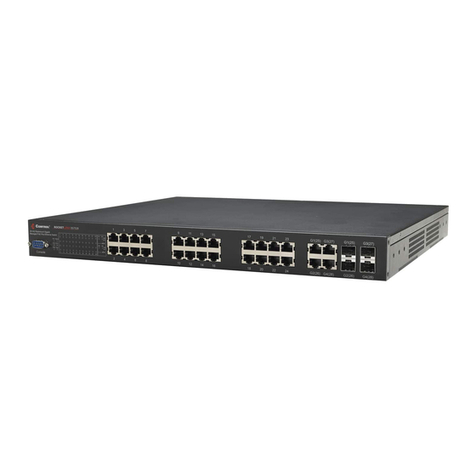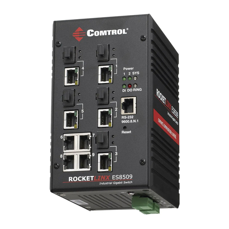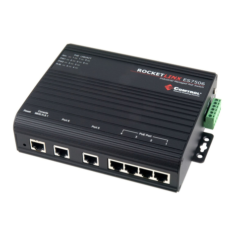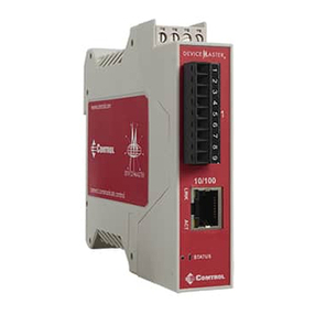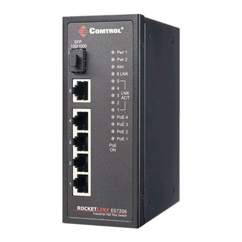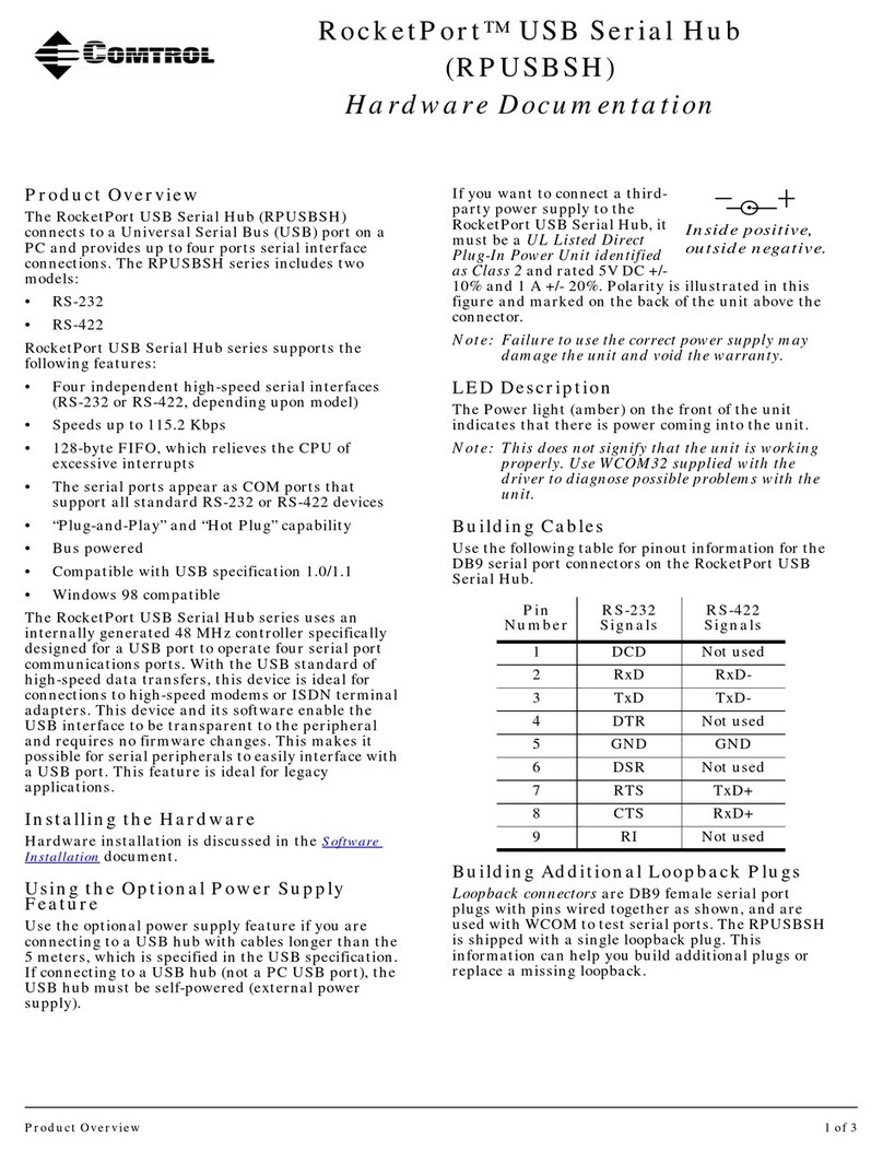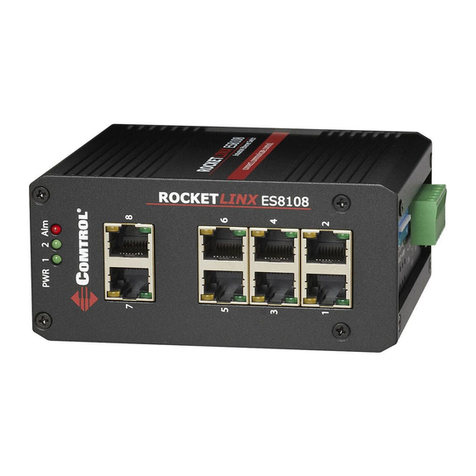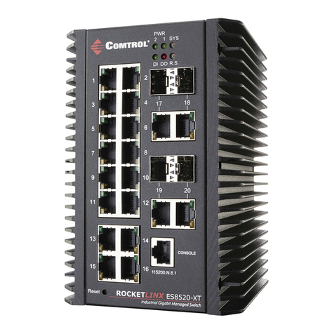
MOUNTING THE ACS7106
Make sure that you use appropriate screws when
securing the ACS7106.
In UL294 installations, #8 self-tapping screws can be
used to mount the ACS7106. Use one or two screws on
each side to mount the ACS7106.
GROUNDING THE ACS7106
The ACS7106 must be tied to earth ground to ensure
the system meets EMC/EMI requirements.
Using a screw driver, loosen the earth ground screw
on the side of the ACS7106 and then tighten the screw
after the earth ground wire (12-14AWG) is connected.
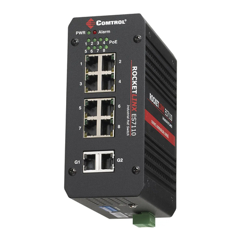
SETTING THE DIP SWITCHES
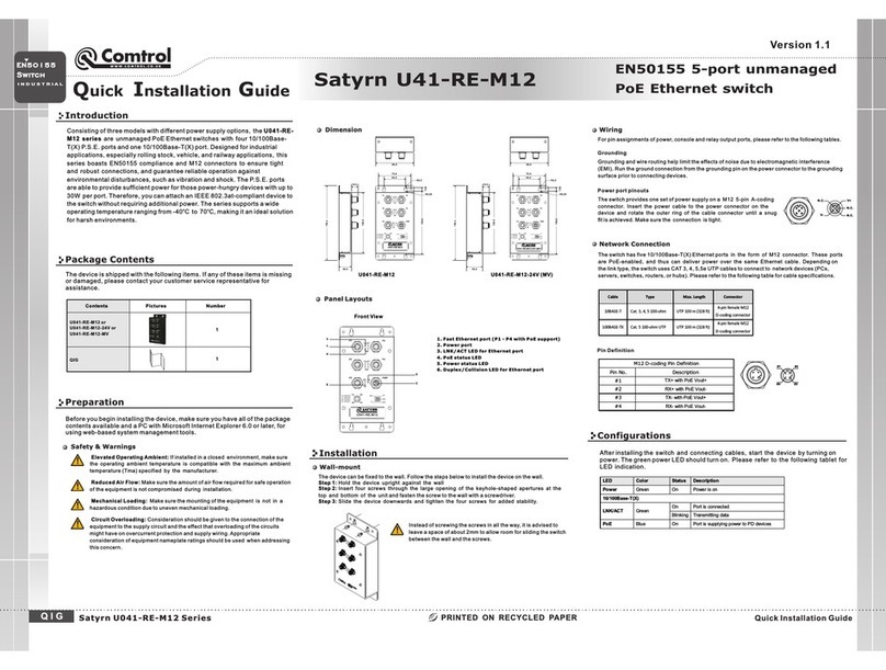
The ACS7106 has a 6-pin DIP switch located on the side
panel to congure the alarm relay output. This table
shows the DIP switch mapping to the corresponding
PoE and Gigabit ports.
DIP Switch Setting Description
PoE Ports
1-4 (DIPs 1-4)
On Enables the alarm for the
corresponding PoE port
Off (Default) Disables the alarm for the
corresponding PoE port
Gigabit Ports
5-6 (DIPs 5-6)
On Enables the alarm for the
corresponding Gigabit port
Off (Default) Disables the alarm for the
corresponding Gigabit port
NOTE: If a port is not connected, make sure that the
corresponding DIP switch remains in the OFF position
so that the alarm is not activated.
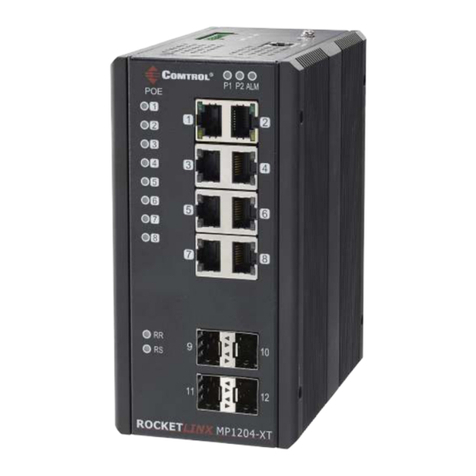
CONNECTING ETHERNET PORTS
Connect one end of an Ethernet cable into the Ethernet
port of the ACS7106 and the other end to the attached
networking device:
• Ports 1-4 are Fast Ethernet (10/100BASE-TX) PoE that
support IEEE 802.3af/802.3at (PoE+)
• Ports 5-6 are Gigabit (10/100/100BASE-TX)
Half and full-duplex connections are supported with
auto-negotiated link speed and duplex mode. Auto
MDI/MDIX enables direct connection of another hub or
switch without the need for crossover cabling. Link/Act
LEDs are lit to indicate trac and link status. See the
LEDs subsection on back for more information.
NOTE: The ACS7106 is to be connected to PoE networks
without routing to outside the plant.
Always make sure that the cables between the
switches and attached devices (for example, switch,
hub or workstation) are less than 100 meters (328 feet).
Use the following cabling guidelines:
• IEEE 802.3af: 4-pair UTP/STP Category 5 or higher
cable, EIA/TIA-568 100-ohm
• IEEE 802.3at: 4-pair UTP/STP Category 5e/6 or higher
cable, EIA/TIA-568 100-ohm
• Uplink ports
• 10BASE-T: 2-pair UTP/STP Category 3, 4, 5, or
higher cable, EIA/TIA-568 100 ohm
• 100BASE-TX: 2-pair UTP/STP Category 5 or higher
cable, EIA/TIA-568 100 ohm
• 1000BASE-TX: 4-pair UTP/STP Category 5 or
higher cable, EIA/TIA-568 100 ohm
Pin 10/100BASE-TX PoE
(Alternative B) 1000BASE-TX
1 RX + BI_DA+
2 RX - BI_DA+
3 TX + BI_DB+
4 Vport+ BI_DC+
5 Vport+ BI_DC-
6 TX - BI_DB-
7 Vport- BI_DD+
8 Vport- BI_DD-
WIRING THE POWER INPUTS
The power supply input range is 12-24VDC with a
maximum power consumption of 8W without PoE PD
loading.
Wiring methods shall be compliant with National
Electrical Code/NFPA 70/ANSI.
NOTE: Power should be disconnected from the power
supply before connecting it to the switch. Otherwise, your
screwdriver blade can inadvertently short your terminal
connections to the grounded enclosure.
1. Disconnect the power terminal block from the ACS7106.
2. Insert the positive and negative wires into PWR+ and
PWR- contacts.
3. Tighten the wire-clamp screws to prevent the wires from
being loosened.
NOTES:
•
For UL installations, the ACS7106 is intended to be used
with a regulated UL Listed Class 2 or LPS (Limited Power
Supply).
•
For the highest specied PoE output load, the ACS 7106
is intended to be used with a regulated UL Listed Class 2
or LPS rated at:
•
24VDC @ 4.8A or 12VDC @ 6.8A, minimum.
(UL60950 Installation)
•
24VDC @ 4.5A or 12VDC @ 6.8A, minimum.
(UL294 Installation)
WIRING THE ALARM RELAY OUTPUT
The alarm relay output or digital output (DO) contacts are
on the terminal block connector. The alarm relay output
contacts are normally open. The alarm relay output
contacts close when the alarm is enabled with the DIP
switches and there is a port link failure or PoE failure on a
port.
NOTE: The alarm relay is not intended to be an indication of
a burglary alarm condition.
The alarm relay output contacts support up to 1A at
24VDC. Do not apply voltage and current higher than the
specications.
The alarm relay output is controlled by the
pre-dened operating rules. To activate the alarm relay
output function, refer to the
Setting the DIP Switches
discussion.
- 6 -
- 5 - - 7 -
PWR
+
-
12 - 24AWG Wires
Wiring Positive Power Supplies
Power Supply
12 -24VDC
(UL Listed*)
*UL 294: A regulated UL294 approved power supply is required to meet
UL294 installation requirements.
v-
v
+
PWR
12 - 24AWG Wires
24VDC/1A
Alarm Relay Output
Alarm Control
DIP Switch
+
Alarm
Relay
Earth Ground
Power
Source
Buzzer/PLC
Input
Example of ACS7106 Mounted to Panel/Wall
mounting brackets
