manuals.online logo
Brands
  1. Home
  2. •
  3. Brands
  4. •
  5. Comtrol
  6. •
  7. Switch
  8. •
  9. Comtrol RocketPort RPUSBSH Operator's manual

Comtrol RocketPort RPUSBSH Operator's manual

Product Overview 1 of 3
Product Overview
The RocketPort USB Serial Hub (RPUSBSH)
connects to a Universal Serial Bus (USB) port on a
PC and provides up to four ports serial interface
connections. The RPUSBSH series includes two
models:
•RS-232
•RS-422
RocketPort USB Serial Hub series supports the
following features:
•Four independent high-speed serial interfaces
(RS-232 or RS-422, depending upon model)
•Speeds up to 115.2 Kbps
•128-byte FIFO, which relieves the CPU of
excessive interrupts
•The serial ports appear as COM ports that
support all standard RS-232 or RS-422 devices
•“Plug-and-Play” and “Hot Plug” capability
•Bus powered
•Compatible with USB specification 1.0/1.1
•Windows 98 compatible
The RocketPort USB Serial Hub series uses an
internally generated 48 MHz controller specifically
designed for a USB port to operate four serial port
communications ports. With the USB standard of
high-speed data transfers, this device is ideal for
connections to high-speed modems or ISDN terminal
adapters. This device and its software enable the
USB interface to be transparent to the peripheral
and requires no firmware changes. This makes it
possible for serial peripherals to easily interface with
a USB port. This feature is ideal for legacy
applications.
Installing the Hardware
Hardware installation is discussed in the Software
Installation document.
Using the Optional Power Supply
Feature
Use the optional power supply feature if you are
connecting to a USB hub with cables longer than the
5 meters, which is specified in the USB specification.
If connecting to a USB hub (not a PC USB port), the
USB hub must be self-powered (external power
supply).
If you want to connect a third-
party power supply to the
RocketPort USB Serial Hub, it
must be a UL Listed Direct
Plug-In Power Unit identified
as Class 2 and rated 5V DC +/-
10% and 1 A +/- 20%. Polarity is illustrated in this
figure and marked on the back of the unit above the
connector.
Note: Failure to use the correct power supply may
damage the unit and void the warranty.
LED Description
The Power light (amber) on the front of the unit
indicates that there is power coming into the unit.
Note: This does not signify that the unit is working
properly. Use WCOM32 supplied with the
driver to diagnose possible problems with the
unit.
Building Cables
Use the following table for pinout information for the
DB9 serial port connectors on the RocketPort USB
Serial Hub.
Building Additional Loopback Plugs
Loopback connectors are DB9 female serial port
plugs with pins wired together as shown, and are
used with WCOM to test serial ports. The RPUSBSH
is shipped with a single loopback plug. This
information can help you build additional plugs or
replace a missing loopback.
Pin
Number RS-232
Signals RS-422
Signals
1DCD Not used
2RxD RxD-
3TxD TxD-
4DTR Not used
5GND GND
6DSR Not used
7RTS TxD+
8CTS RxD+
9RI Not used
o
.
- +
Inside positive,
outside negative.
RocketPort™ USB Serial Hub
(RPUSBSH)
Hardware Documentation
Operating Conditions 2 of 3
Wire the following pins
together for an RS-232/422
loopback plug.
•Pins 1 to 4 to 6
•Pins 2 to 3
•Pins 7 to 8 to 9
Operating Conditions
The following tables illustrate RocketPort USB
Serial Hub conditions and specifications.
FCC Notices
Radio Frequency Interference (RFI) (FCC
15.105)
This equipment has been tested and found to comply
with the limits for Class A digital devices pursuant
to Part 15 of the FCC Rules.
This equipment generates, uses, and can radiate
radio frequency energy, and if not installed and used
in accordance with the instruction manual, may
cause harmful interference to radio communications.
However, there is no guarantee that interference will
not occur in a particular installation. If this
equipment does cause harmful interference to radio
or television reception, which can be determined by
turning the equipment off and on, the user is
encouraged to try and correct the interference by one
or more of the following measures:
•Reorient or relocate the receiving antenna.
•Increase the separation between the equipment
and the receiver.
•Connect the equipment to an outlet on a circuit
different from that to which the receiver is
connected.
•Consult the dealer or an experienced radio/TV
technician for help.
Labeling Requirements (FCC 15.19)
This equipment complies with Part 15 of FCC Rules.
Operation is subject to the following two conditions:
•This device may not cause harmful interference,
and
•This device must accept any interference
received, including interference that may cause
undesired operation.
Modifications (FCC 15.21)
Changes or modifications to this equipment not
expressly approved by Comtrol Corporation may void
the user’s authority to operate this equipment.
Serial Cables (FCC 15.27)
This equipment is certified for Class A operation
when used with shielded cables.
Technical Support
Comtrol has a staff of support technicians available
to help you. Before you call, please have the following
information available:
•Model number
•Serial number
•Type of USB hub (if appropriate)
•Operating system type and release
•Device driver version
•PC make, model, and speed
Environmental
Condition Value
Air temperature:
System on
System off 0 to 40oC
-20 to 85oC
Humidity (non-condensing):
System on
System off 8% to 80%
20% to 80%
Altitude 0 to 10,000 feet
Electromagnetic Compliance Status
Emission:
Canadian EMC requirements
CISPR-22/EN55022 Class A
FCC PART 15, Subpart J: Class A Yes
Immunity:
EN50082: 801-2 ESD, 801-3 RF,
801-4 FT Yes
UL Recognized Yes
Topic Hardware
Specification
Baud rate 115 Kbps
Bus interface USB
Control by device driver:
Data bits
Parity
Stop bits
7 or 8
Odd, Even, None
1 or 2
Current consumption:
RS-232
RS-422 125 mA +/- 20%
136 mA +/- 20%
Dimensions 3” x 4.375” x 1.75”
Mean time between failure 70.2 years
Number of serial ports 4
Optional power supply
(max) 5V DC +/- 10% and
1 A
Output (voltage swing):
RS-232
RS-422 +5V min, +7.5V typical
+2.5 min, Max = VCC
Power consumption < 1 W
Surge protection 10 KV ESD
Weight 6.5oz
Pin 1 Pin 5
Pin 6 Pin 9
RS-232 Only
(Back View)
Comtrol Headquarters Europe
Phone (612) 494-4100 +44 (0)1869 323220
FAX (612) 494-4199 +44 (0)1869 323211
Email [email protected] [email protected]
web site www.comtrol.com www.comtrol.co.uk
ftp site ftp.comtrol.com
Technical Support 3 of 3
First Edition, January 24, 2000
Copyright © 1999 Comtrol Corporation.
All Rights Reserved.
RocketPort is a registered trademark of the Comtrol
Corporation. Other product and company names
mentioned herein may be the trademarks of their
respective owners.
Comtrol Corporation makes no representations or
warranties with regard to the contents of this
reference card or to the suitability of any Comtrol
product for any particular purpose. Specifications
subject to change without notice. Some software or
features may not be available at the time of
publication. Contact your reseller for current product
information.
Document Number: 2000113 Rev A

Other Comtrol Switch manuals

Comtrol RocketLinx ES8108 User manual

Comtrol

Comtrol RocketLinx ES8108 User manual

Comtrol RocketLinx MP1204-XT User manual

Comtrol

Comtrol RocketLinx MP1204-XT User manual

Comtrol Rocket linx ES8508 User manual

Comtrol

Comtrol Rocket linx ES8508 User manual

Comtrol ROCKET LINX MP1204-XT User manual

Comtrol

Comtrol ROCKET LINX MP1204-XT User manual

Comtrol RocketPort Operator's manual

Comtrol

Comtrol RocketPort Operator's manual

Comtrol ROCKETLINX ES7105 User manual
Comtrol

Comtrol ROCKETLINX ES7105 User manual

Comtrol ROCKETLINX ES8509-XT User manual

Comtrol

Comtrol ROCKETLINX ES8509-XT User manual

Comtrol RocketLinx ES8108 User manual
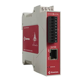
Comtrol

Comtrol RocketLinx ES8108 User manual

Comtrol RocketLinx ES8105 User manual

Comtrol

Comtrol RocketLinx ES8105 User manual

Comtrol DeviceMaster DM-2000 Series Operator's manual
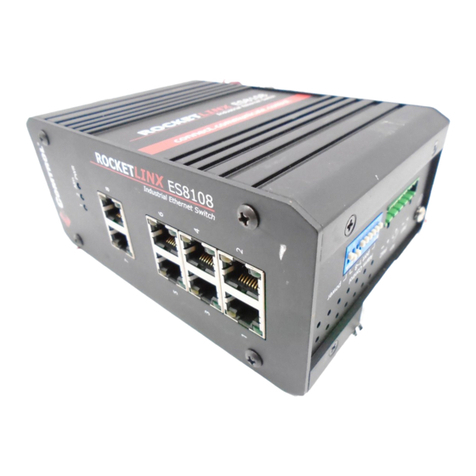
Comtrol

Comtrol DeviceMaster DM-2000 Series Operator's manual

Comtrol ROCKETLINX ES7110-VB User manual

Comtrol

Comtrol ROCKETLINX ES7110-VB User manual

Comtrol ROCKETLINX ES8510 User manual

Comtrol

Comtrol ROCKETLINX ES8510 User manual

Comtrol ROCKETLINX ES8508 User manual

Comtrol

Comtrol ROCKETLINX ES8508 User manual

Comtrol RocketLinx ES7510 User manual

Comtrol

Comtrol RocketLinx ES7510 User manual

Comtrol RocketLinx ES7506 User manual

Comtrol

Comtrol RocketLinx ES7506 User manual

Comtrol Satyrn U041-RE-M12 User manual

Comtrol

Comtrol Satyrn U041-RE-M12 User manual

Comtrol ROCKET LINX ES7506 User manual

Comtrol

Comtrol ROCKET LINX ES7506 User manual

Comtrol RocketLinx ES7528 User manual

Comtrol

Comtrol RocketLinx ES7528 User manual

Comtrol ROCKETLINX ACS7106 User manual

Comtrol

Comtrol ROCKETLINX ACS7106 User manual

Comtrol RocketLinx ES8108 User manual
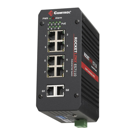
Comtrol

Comtrol RocketLinx ES8108 User manual

Comtrol RocketLinx ES8520-XT User manual
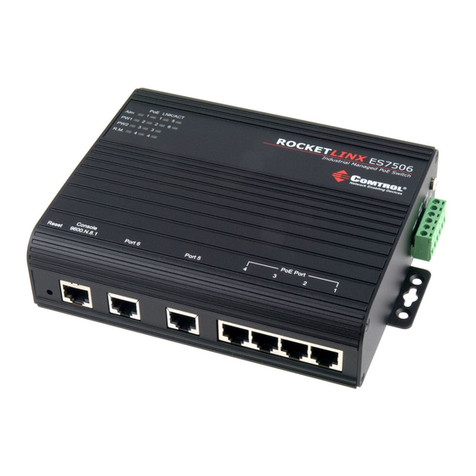
Comtrol

Comtrol RocketLinx ES8520-XT User manual

Comtrol RocketPort Serial Hub Si Operator's manual
Comtrol

Comtrol RocketPort Serial Hub Si Operator's manual

Comtrol Rocketlinx ES8108-GigE User manual

Comtrol

Comtrol Rocketlinx ES8108-GigE User manual

Comtrol ROCKETLINX ES8509-XT User manual
Comtrol

Comtrol ROCKETLINX ES8509-XT User manual

Popular Switch manuals by other brands

Wise T931 manual

Wise

Wise T931 manual

Alps Electric SDKP Series specification

Alps Electric

Alps Electric SDKP Series specification

D-Link xStack DGS-3620 Series reference guide

D-Link

D-Link xStack DGS-3620 Series reference guide

schmersal TESK-S Series operating instructions

schmersal

schmersal TESK-S Series operating instructions

Ross MC1-MK operating instructions

Ross

Ross MC1-MK operating instructions

Siemens SCALANCE XRH-300 product manual

Siemens

Siemens SCALANCE XRH-300 product manual

Interlogix NS3552-8P-2S-V2 Quick installation guide

Interlogix

Interlogix NS3552-8P-2S-V2 Quick installation guide

Ross Acuity Ultrix Acuity Setup manual

Ross

Ross Acuity Ultrix Acuity Setup manual

Juniper OCX1100-48SX quick start guide

Juniper

Juniper OCX1100-48SX quick start guide

GSS PSPT 1000 Assembly instruction

GSS

GSS PSPT 1000 Assembly instruction

Swidget S16008WA quick start guide

Swidget

Swidget S16008WA quick start guide

NETGEAR 200 Series quick start

NETGEAR

NETGEAR 200 Series quick start

mumbi m-AZ3500 user manual

mumbi

mumbi m-AZ3500 user manual

steute ZS 73 Mounting and wiring instructions

steute

steute ZS 73 Mounting and wiring instructions

ViziT 19w 14.4v EU Operating	 instruction

ViziT

ViziT 19w 14.4v EU Operating instruction

C4i HDC-SPB116 user manual

C4i

C4i HDC-SPB116 user manual

Altusen KM0032 user manual

Altusen

Altusen KM0032 user manual

Altinex MULTI-TASKER MT104-107 user guide

Altinex

Altinex MULTI-TASKER MT104-107 user guide

manuals.online logo
manuals.online logoBrands
  • About & Mission
  • Contact us
  • Privacy Policy
  • Terms and Conditions

Copyright 2025 Manuals.Online. All Rights Reserved.