manuals.online logo
Brands
  1. Home
  2. •
  3. Brands
  4. •
  5. Comtrol
  6. •
  7. Switch
  8. •
  9. Comtrol Satyrn U041-RE-M12 User manual

Comtrol Satyrn U041-RE-M12 User manual

FDX
V-
V+
Tx+ Rx+
Tx-Rx-
N.C.
N.C.
N.C.
P1 P2
P3 P4
P5 PWR
PoE
PoE
Tx+: PoE Vo ut+
Tx- : PoE Vo ut+
Rx+: PoE Vo ut-
Rx- : PoE Vou t-
TPS- 141T X-M1 2
Quick Installation Guide
Version 1.1
Quick Installation Guide
Introduction
PRINTED ON RECYCLED PAPER
Q I G
Consisting of three models with different power supply options, the U041-RE-
M12 series are unmanaged PoE Ethernet switches with four 10/100Base-
T(X) P.S.E. ports and one 10/100Base-T(X) port. Designed for industrial
applications, especially rolling stock, vehicle, and railway applications, this
series boasts EN50155 compliance and M12 connectors to ensure tight
and robust connections, and guarantee reliable operation against
environmental disturbances, such as vibration and shock. The P.S.E. ports
are able to provide sufficient power for those power-hungry devices with up to
30W per port. Therefore, you can attach an IEEE 802.3at-compliant device to
the switch without requiring additional power. The series supports a wide
o o
operating temperature ranging from -40 C to 70 C, making it an ideal solution
for harsh environments.
Package Contents
Installation
Wall-mount
The device ca n be fix ed to the wall. Fol low th e steps below to instal l the device on the wall.
Step 1: Hold th e devi ce upright agai nst th e wall
Step 2: Inser t four screws through the large opening of th e keyh ole-shaped apertures at th e
top and bottom of th e unit a nd fasten the scr ew to th e wall with a screw driv er.
Step 3: Slide t he dev ice downwards and ti ghte n the four screws for added stab ility.
The device is shipped with the following items. If any of these items is missing
or damaged, please contact your customer service representative for
assistance.
Preparation
Before you begin installing the device, make sure you have all of the package
contents available and a PC with Microsoft Internet Explorer 6.0 or later, for
using web-based system management tools.
Elevated Op erating Ambient: If ins talled in a closed envi ronm ent, make sure
the operating ambient te mper ature is compat ible w ith the maximum ambie nt
temperatu re (Tma) specified by t he man ufacturer.
Reduced Air Flo w: Make sure the am ount o f air flow required for s afe operation
of the equipm ent is not compromise d duri ng installation.
Mechanica l Loading: Make sure th e moun ting of the equip ment i s not in a
hazardous c ondi tion due to uneve n mech anical loading.
Circuit Ove rloading: Conside rati on should be give n to the c onnection of the
equipment t o the su pply circuit an d the effect that overload ing of t he circuits
might have on o verc urrent protec tion a nd supply wiring. Appr opri ate
considera tion o f equipment nam epla te ratings should be us ed whe n addressing
this concer n.
Safety & Warnings
For pin assig nmen ts of power, conso le and r elay output ports, pl ease refer to the follo wing t ables.
Contents
U041 -RE-M 12 or
U041 -RE-M 12- 24V or
U041 -RE-M 12- MV
Pictures Number
1
QIG 1
Dimension
Panel Layouts
Front View
1. F ast Et her n et po r t (P1 - P 4 with P oE sup por t )
2. P ower p ort
3. L NK/A CT LE D f or Et h ern et por t
4. P oE sta tus L E D
5. P ower s tat u s LED
6. D uple x/C o lli s ion L ED for E ther net p o rt
Wiring
Grounding
Grounding a nd wir e routing help li mit th e eff ects of noise due t o elec tromagnetic inter ference
(EMI). Run th e grou nd connection f rom th e grounding pin on the po wer co nnector to the gr ound ing
surface pri or to connecting devi ces.
Power port pi nouts
The switch pr ovid es one set of power s uppl y on a M12 5-pin A-coding
connector. I nser t the power cable to the power connector on the
device and rotat e the outer ring of the cable conn ecto r until a snug
fit is achieve d. Make sure the connec tion i s tight.
Network Connection
The switch ha s five 10/100Base-T (X) Et hernet ports in t he for m of M12 connector. Thes e ports
are PoE-enabled, and thus can deliver power ove r the same Ethernet cab le. De pending on
the link type , the switch uses CAT 3, 4, 5,5e U TP ca bles to connect t o netw ork devices (PCs,
servers, sw itches, routers, or h ubs) . Please refer to t he fol lowing table for cabl e specifications.
Satyrn U41-RE-M12
Satyrn U041-RE-M12 Series
Sw i tch
EN5 01 5 5
EN50155 5-port unmanaged
PoE Ethernet switch
I N D U S T R I A L
1
3
4
6 2
5
Instead of sc rewing the screws in al l the wa y, it is advised to
leave a space o f abou t 2mm to allow room f or sli ding the switch
between the w all an d the screws.
Cable Type Max. Length Connector
10BASE-T Cat. 3, 4, 5 100-ohm UTP 100 m (328 ft) 4-pin female M12
D-coding connector
100BASE-TX Cat. 5 100-ohm UTP UTP 100 m (328 ft)
4-pin female M12
D-coding connector
Pin Definit ion
#1 #2
#3
#4
Configurations
After installing the switch and connecting cables, start the device by turning on
power. The green power LED should turn on. Please refer to the following tablet for
LED indication.
R2. 5
R4. 00
7.5 0
150 .0
44. 4
73. 9
FDX
V-
V+
Tx+ Rx+
Tx-Rx-
N.C.
N.C.
N.C.
P1 P2
P3 P4
P5 PWR
PoE
PoE
Tx+: PoE Vout+
Tx- : PoE Vout+
Rx+: PoE Vout-
Rx-: Po E Vout-
178 .2
53. 0
15. 0
138 .0
88. 9
V-
V+
N.C .
N.C .
N.C .
LED Color Status Description
Power Green On Power is on
10/100Base-T(X)
On Port is connected
LNK/ACT Green Blinking Transmitting data
PoE Blue On Port is supplying power to PD devices
M12 D-coding Pin Definition
Pin No. Description
#1 TX+ with PoE Vout+
#2 RX+ with PoE Vout-
#3 TX- with PoE Vout+
#4 RX- with PoE Vout-
178 .2
15. 0
138 .0
40. 0
R2. 5
R4. 00
7.5 0
150 .0
44. 4
73. 9
FDX
V-
V+
Tx+ Rx+
Tx-Rx-
N.C.
N.C.
N.C.
P1 P2
P3 P4
P5 PWR
PoE
PoE
Tx+: PoE Vout+
Tx- : PoE Vout+
Rx+: PoE Vout-
Rx-: Po E Vout-
88. 9
U041-RE-M 12 U041-RE-M 12-2 4V (MV)
U041 -RE -M1 2 U041 -RE-M 12-24 V (MV)
U04 1- RE -M1 2
Q I G Quick Installation Guide
PRINTED ON RECYCLED PAPER
Quick Installation Guide
Com t r ol UK Ltd.
Copyr igh t© 2017 Comtro l UK Lt d
All rights res erv ed.
TEL: +(0) 18 69 352740
FAX: +(0 ) 186 9 351848
Webs ite: www.comtrol. co. uk
E-mai l: sa les@comtro l.co.uk
Version 1.1
Q I G
Sw i tch
EN5 01 5 5
EN50155 5-port unmanaged
PoE Ethernet switch
I N D U S T R I A L
Specifications
Po wer
In pu t Po we r ( 5- pi n M12
A-co di ng )
Powe r Co ns u mp ti on( Typ .)
50 ~5 7 VD C po w er i np ut i n M1 2
co nn ec to r
3 Wat ts ( P.D. n ot i nc l ud ed )
Ph ysi cal C ha r ac t er ist ic
En cl osu re I P- 40
Di me nsi on ( W x D x H) 88.9 (W ) x 40 (D ) x 17 8. 2 (H )
mm ( 3. 5 x 1. 57 x 7 . 02 i nc h. )
Wei ght ( g) 36 3 g
En vir onm en t al
o o
-4 0 to 8 5 C ( -4 0 to 1 8 5 F )
St or ag e Tem pe ra tur e
5% t o 95 % No n- c on de ns in g
Op er at ing H um id i ty
Re gul ato ry A p pr o va ls
FC C Pa rt 1 5, C IS PR (E N5 50 22 ) cla ss A , EN 50 155 ( EN 50 12 1-3 -2 , EN 55 0 11 , EN 50 12 1 -4 )
EM I
EN 61 00 0- 4 -2 ( ES D) , EN 6 10 00 -4 -3 (R S) , EN 61 000 -4 -4 ( EF T ), E N6 10 0 0- 4- 5 (S ur g e) ,
EN 61 00 0- 4 -6 ( CS ), E N61 00 0- 4- 8, EN 61 00 0- 4-1 1
EM S
IE C6 00 68 - 2- 27
Sh oc k
IE C6 00 68 - 2- 32
IE C6 00 68 - 2- 6
Vi br at ion
Fr ee Fal l
Wa rra nty 5 y ea rs
EN 60 95 0- 1
Sa fe ty
Ov er lo a d Cu rr ent P ro te c ti on
Reve rs e Po la rit y Pr ot e ct io n
Pr es en t
Pr es en t
o o
-4 0 to 7 0 C ( -4 0 to 1 5 8 F )
Op er at ing Tem perat ur e
OR in g S wi tch M od e l
10 /1 00 Ba se -T( X) wi th P.S .E .
Port s in M 12 A uto M DI /MD IX 4 x M1 2 co nne cto r (4 -pi n M12 D -c odi ng )
Ph ysi cal P or t s
Te chn olo gy
Et he rne t St an d ar ds
IE EE 8 02. 3 fo r 10 B as e-T
IE EE 8 02. 3u f or 1 0 0B as e-TX
IE EE 8 02. 3x f or F l ow c on tro l
IE EE 8 02. 3a t Po E sp eci fi cat io n (u p t o 30 Wa tts p er p or t f or P.S .E .)
U0 41 - RE -M1 2
St or e-a nd -F or wa r d
Pr oc ess in g
10 /1 00 Ba se -T( X) Port s in
M1 2 Au to M D I/ MD IX 1 x M1 2 co nne cto r (4 -pi n M12 D -c odi ng )
U0 41 - RE -M1 2- 24V
12 ~5 7 VD C po w er i np ut i n M1 2
co nn ec to r
3. 8 Wat ts (P.D. n ot in cl ud ed )
45 0g
U0 41 - RE -M1 2- MV
72 ~1 10 V DC p o we r in pu t in M 1 2
co nn ec to r
7 Wat ts ( P.D. n ot i nc l ud ed )
57 3g
U041-RE-M12 Series
Satyrn U041-RE-M12 Series
PoE Ou tp ut P ow e r 12 0 Wat ts 60 Wa tt s (12 ~2 4V DC ) /
12 0 Wat ts (2 4~ 57 VD C) 60 Wa tt s
88 .9 (W ) x5 3 (D ) x 17 8. 2( H ) mm ( 3. 5 x 2. 09 x 7 . 02 i nc h. )

This manual suits for next models

2

Other Comtrol Switch manuals

Comtrol ROCKETLINX ES7206-XT User manual

Comtrol

Comtrol ROCKETLINX ES7206-XT User manual

Comtrol ROCKETLINX ES8508 User manual

Comtrol

Comtrol ROCKETLINX ES8508 User manual

Comtrol DeviceMaster DM-2000 Series Operator's manual

Comtrol

Comtrol DeviceMaster DM-2000 Series Operator's manual

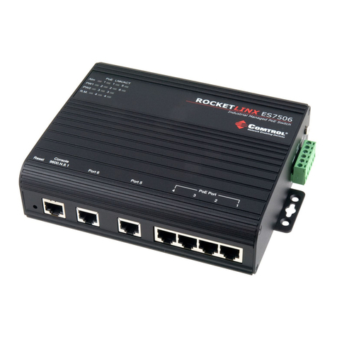
Comtrol ROCKET LINX ES7506 User manual

Comtrol

Comtrol ROCKET LINX ES7506 User manual

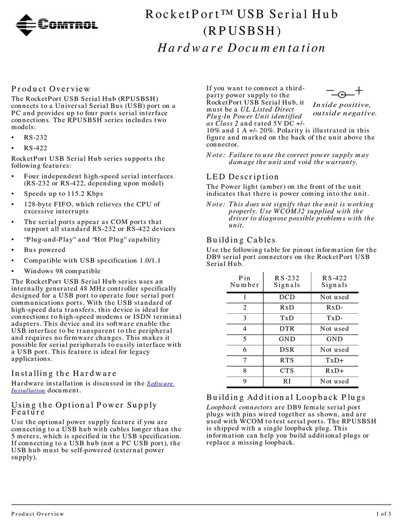
Comtrol RocketPort RPUSBSH Operator's manual

Comtrol

Comtrol RocketPort RPUSBSH Operator's manual

Comtrol Rocketlinx ES8108-GigE User manual

Comtrol

Comtrol Rocketlinx ES8108-GigE User manual

Comtrol RocketLinx ES8108 User manual

Comtrol

Comtrol RocketLinx ES8108 User manual

Comtrol RocketPort Serial Hub Si Operator's manual

Comtrol

Comtrol RocketPort Serial Hub Si Operator's manual

Comtrol RocketLinx ES7510 User manual

Comtrol

Comtrol RocketLinx ES7510 User manual

Comtrol RocketLinx ES8108 User manual

Comtrol

Comtrol RocketLinx ES8108 User manual

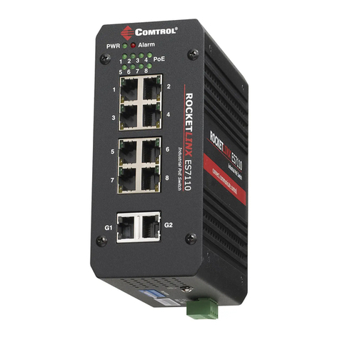
Comtrol ROCKETLINX ES7110-VB User manual

Comtrol

Comtrol ROCKETLINX ES7110-VB User manual

Comtrol ROCKETLINX ACS7106 User manual

Comtrol

Comtrol ROCKETLINX ACS7106 User manual

Comtrol RocketLinx ES8108 User manual

Comtrol

Comtrol RocketLinx ES8108 User manual

Comtrol RocketPort Parts list manual

Comtrol

Comtrol RocketPort Parts list manual

Comtrol Rocket linx ES8508 User manual

Comtrol

Comtrol Rocket linx ES8508 User manual

Comtrol ROCKETLINX ES8510 User manual

Comtrol

Comtrol ROCKETLINX ES8510 User manual

Comtrol RocketLinx ES7528 User manual

Comtrol

Comtrol RocketLinx ES7528 User manual

Comtrol RocketPort Operator's manual

Comtrol

Comtrol RocketPort Operator's manual

Comtrol RocketLinx ES8108 User manual

Comtrol

Comtrol RocketLinx ES8108 User manual

Comtrol ROCKETLINX ES7105 User manual

Comtrol

Comtrol ROCKETLINX ES7105 User manual

Comtrol RocketLinx ES8520-XT User manual

Comtrol

Comtrol RocketLinx ES8520-XT User manual

Comtrol ROCKETLINX ES7510-XT User manual

Comtrol

Comtrol ROCKETLINX ES7510-XT User manual

Comtrol ROCKETLINX ES8509-XT User manual

Comtrol

Comtrol ROCKETLINX ES8509-XT User manual

Comtrol RocketLinx ES7506 User manual

Comtrol

Comtrol RocketLinx ES7506 User manual

Popular Switch manuals by other brands

Planet Networking & Communication WGSW-48040HP Command guide

Planet Networking & Communication

Planet Networking & Communication WGSW-48040HP Command guide

Zigen SW-42Plus quick start guide

Zigen

Zigen SW-42Plus quick start guide

Siemens SIRIUS 3RT2916-4MC00 Original operating instructions

Siemens

Siemens SIRIUS 3RT2916-4MC00 Original operating instructions

Perle IDS-409-SFP Hardware installation guide

Perle

Perle IDS-409-SFP Hardware installation guide

D-Link DGS-1210/ME series Hardware installation guide

D-Link

D-Link DGS-1210/ME series Hardware installation guide

Orbis ALPHA user manual

Orbis

Orbis ALPHA user manual

Atlantis Land 1000BASE-T user guide

Atlantis Land

Atlantis Land 1000BASE-T user guide

SDMO VERSO S Operating and instruction manual

SDMO

SDMO VERSO S Operating and instruction manual

Key Digital KD-IP922ENC-II manual

Key Digital

Key Digital KD-IP922ENC-II manual

Siemens SIMATIC HMI operating instructions

Siemens

Siemens SIMATIC HMI operating instructions

SMSC LAN9514 datasheet

SMSC

SMSC LAN9514 datasheet

SEIAOTEK ST-M2404PX user manual

SEIAOTEK

SEIAOTEK ST-M2404PX user manual

Edge ES6 manual

Edge

Edge ES6 manual

Keysight U1816A Operating and service manual

Keysight

Keysight U1816A Operating and service manual

MPL MAGBES Technical reference manual

MPL

MPL MAGBES Technical reference manual

Minicom 1SU70017 quick start guide

Minicom

Minicom 1SU70017 quick start guide

Symbol WS5100 Series Reviewer's guide

Symbol

Symbol WS5100 Series Reviewer's guide

Cisco Nexus 5548UP Configuration guide

Cisco

Cisco Nexus 5548UP Configuration guide

manuals.online logo
manuals.online logoBrands
  • About & Mission
  • Contact us
  • Privacy Policy
  • Terms and Conditions

Copyright 2025 Manuals.Online. All Rights Reserved.