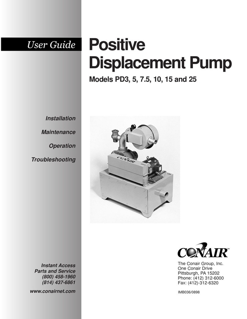
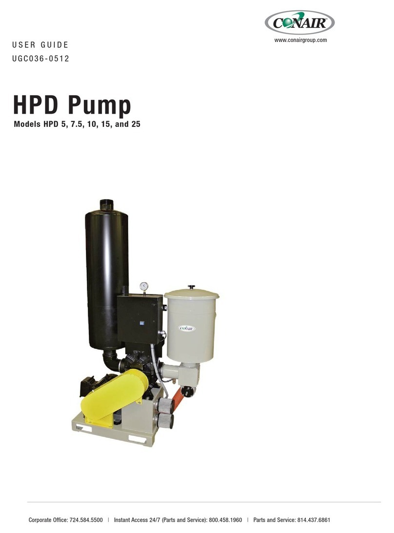
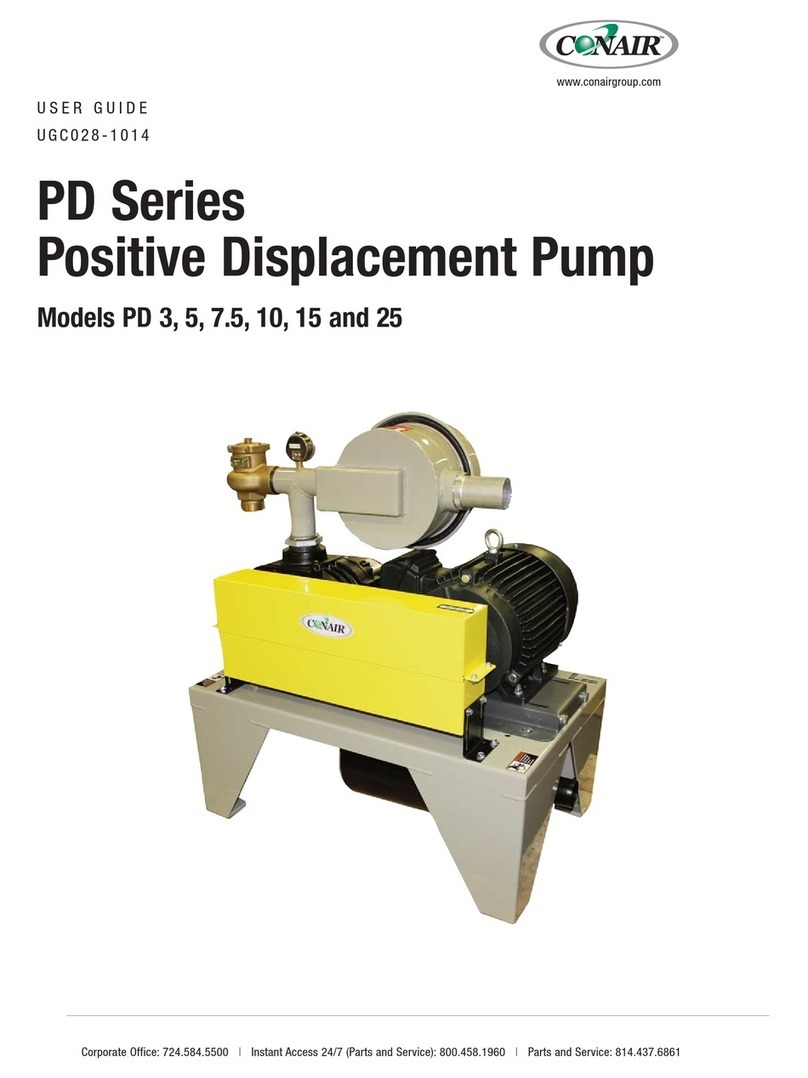
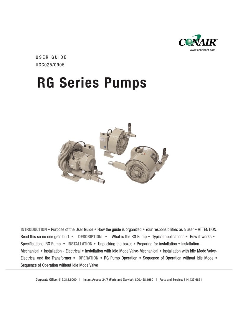
Conair LDP-5 User manual

LDP Pump
Long Distance, Claw-Style Vacuum Pump
Corporate Office: 724.584.5500 lInstant Access 24/7 (Parts and Service): 800.458.1960 l Parts and Service: 814.437.6861
USER GUIDE
UGC039-0619
www.conairgroup.com

Please record your equipment’s
model and serial number(s) and
the date you received it in the
spaces provided.
It’s a good idea to record the model and serial number(s) of your equipment and the date
you received it in the User Guide. Our service department uses this information, along with
the manual number, to provide help for the specific equipment you installed.
Please keep this User Guide and all manuals, engineering prints and parts lists together for
documentation of your equipment.
Date:
Manual Number: UGC039-0619
Serial Number(s):
Model Number(s):
DISCLAIMER: Conair shall not be liable for errors contained in this User Guide or for incidental, consequen-
tial damages in connection with the furnishing, performance or use of this information. Conair makes no
warranty of any kind with regard to this information, including, but not limited to the implied warranties of
merchantability and fitness for a particular purpose.
Copyright 2019 l Conair l All rights reserved

Table of Contents l i
Table of Contents
1-1 Introduction
Purpose of the User Guide . . . . . . . . . . . . . . . . . . . . . . . . . . . . . . . . . . . . . . . 1-2
How the Guide Is Organized . . . . . . . . . . . . . . . . . . . . . . . . . . . . . . . . . . . . . . 1-2
Your Responsibilities as a User. . . . . . . . . . . . . . . . . . . . . . . . . . . . . . . . . . . . 1-2
ATTENTION: Read this so no one gets hurt . . . . . . . . . . . . . . . . . . . . . . . . . . . 1-3
2-1 Description
What is the Conair LDP . . . . . . . . . . . . . . . . . . . . . . . . . . . . . . . . . . . . . . . . . .2-2
Typical Applications. . . . . . . . . . . . . . . . . . . . . . . . . . . . . . . . . . . . . . . . . . . . .2-2
How the LDP Works . . . . . . . . . . . . . . . . . . . . . . . . . . . . . . . . . . . . . . . . . . . . 2-2
Specifications: . . . . . . . . . . . . . . . . . . . . . . . . . . . . . . . . . . . . . . . . . . . . . . . . 2-6
3-1 Installation
Preparing for Installation . . . . . . . . . . . . . . . . . . . . . . . . . . . . . . . . . . . . . . . . 3-2
Mechanical Installation of the LDP Pump . . . . . . . . . . . . . . . . . . . . . . . . . . . . 3-3
Electrical Installation of the LDP Pump. . . . . . . . . . . . . . . . . . . . . . . . . . . . . . 3-4
3-Phase Power Wiring . . . . . . . . . . . . . . . . . . . . . . . . . . . . . . . . . . . . . . . . . . 3-4
Pump Start Signal Wiring . . . . . . . . . . . . . . . . . . . . . . . . . . . . . . . . . . . . . . . . 3-5
Idle Mode Valve Wiring . . . . . . . . . . . . . . . . . . . . . . . . . . . . . . . . . . . . . . . . . 3-5
Compressed Air Installation . . . . . . . . . . . . . . . . . . . . . . . . . . . . . . . . . . . . . . 3-5
4-1 Operation
Check Rotation. . . . . . . . . . . . . . . . . . . . . . . . . . . . . . . . . . . . . . . . . . . . . . . . 4-2
5-1 Maintenance
Warnings and Cautions . . . . . . . . . . . . . . . . . . . . . . . . . . . . . . . . . . . . . . . . . 5-2
Preventative Maintenance Schedule. . . . . . . . . . . . . . . . . . . . . . . . . . . . . . . . 5-3
Filter Cleaning Instructions. . . . . . . . . . . . . . . . . . . . . . . . . . . . . . . . . . . . . . . 5-3
Checking the Level of the Synchronizing Gear Oil. . . . . . . . . . . . . . . . . . . . . . 5-4
Cleaning the Pump Housing . . . . . . . . . . . . . . . . . . . . . . . . . . . . . . . . . . . . . 5-5
Checking the Idle Mode Valve Seals . . . . . . . . . . . . . . . . . . . . . . . . . . . . . . . . 5-5
Cleaning or Replacing the Inlet Air Screen on
the Inlet to the Pump . . . . . . . . . . . . . . . . . . . . . . . . . . . . . . . . . . . . . . 5-6
Removing and Cleaning the Filter Bowl on the
Compressed Air Line . . . . . . . . . . . . . . . . . . . . . . . . . . . . . . . . . . . . . . 5-6
Synchronizing Gear Oil Change Procedure . . . . . . . . . . . . . . . . . . . . . . . . . . . 5-7
(Continued)

iv l Table of Contents
Table of Contents (continued)
6-1 Troubleshooting
Before Beginning . . . . . . . . . . . . . . . . . . . . . . . . . . . . . . . . . . . . . . . . . . . . . 6-2
A Few Words of Caution . . . . . . . . . . . . . . . . . . . . . . . . . . . . . . . . . . . . . . . . . 6-2
LDP Operation Problems . . . . . . . . . . . . . . . . . . . . . . . . . . . . . . . . . . . . . . . . 6-3
AAppendix
Customer Service Information . . . . . . . . . . . . . . . . . . . . . . . . . . . . . . . . . . . . A-1
Warranty Information . . . . . . . . . . . . . . . . . . . . . . . . . . . . . . . . . . . . . . . . . . . A-2

Introduction
Purpose of the User Guide . . . . . . . . . . . . . . . . . 1-2
How the Guide Is Organized . . . . . . . . . . . . . . . . 1-2
Your Responsibilities as a User . . . . . . . . . . . . . . 1-2
ATTENTION: Read This So No One Gets Hurt . . . . . . 1-3
SECTION
1
Introduction l 1-1
1
Introduction

✐
Purpose of the User Guide
This User Guide describes the Conair LDP, or Long Distance Pump and explains step-by-
step how to install and operate this equipment.
Before installing this product, please take a few moments to read the User Guide and review
the diagrams and safety information in the instruction packet. You also should review man-
uals covering associated equipment in your system. This review won’t take long, and it
could save you valuable installation and operating time later.
How the Guide is Organized
Symbols have been used to help organize the User Guide and call your attention to important
information regarding safe installation and operation.
Symbols within triangles warn of conditions that could be hazardous to users or could damage equip-
ment. Read and take precautions before proceeding.
Numbers indicate tasks or steps to be performed by the user.
A diamond indicates the equipment’s response to an action performed by the user.
An open box marks items in a checklist.
A circle marks items in a list.
Indicates a tip. A tip is used to provide you with a suggestion that will help you with the maintenance and
the operation of this equipment.
Indicates a note. A note is used to provide additional information about the steps you are following
throughout the manual.
Your Responsibility as a User
You must be familiar with all safety procedures concerning installation, operation, and
maintenance of this equipment. Responsible safety procedures include:
•Thorough review of this User Guide, paying particular attention
to hazard warnings, appendices, and related diagrams.
•Thorough review of the equipment itself, with careful attention
to voltage sources, intended use and warning labels.
•Thorough review of instruction manuals for associated equipment.
•Step-by-step adherence to instructions outlined in this User Guide.
1
◆
❒
•
✒
1-2 l Introduction

ATTENTION:
Read This So No One Gets Hurt
We design equipment with the user’s safety in mind. You can avoid the potential hazards
identified on this machine by following the procedures outlined below and elsewhere in the
User Guide.
WARNING: Improper installation, operation, or serv-
icing may result in equipment damage or personal
injury.
This equipment should be installed, adjusted, and serviced by qualified techni-
cal personnel who are familiar with the construction, operation, and potential
hazards of this type of machine.
All wiring, disconnects, and fuses should be installed by qualified electrical
technicians in accordance with electrical codes in your region. Always maintain
a safe ground. Do not operate the equipment at power levels other than what
is specified on the machine serial tag and data plate.
WARNING: Voltage hazard
This equipment is powered by three-phase alternating current, as specified on
the machine serial tag and data plate.
A properly sized conductive ground wire from the incoming power supply must
be connected to the chassis ground terminal inside the electrical enclosure.
Improper grounding can result in severe personal injury and erratic machine
operation.
Always disconnect and lock out the incoming main power source before open-
ing the electrical enclosure or performing non-standard operating procedures,
such as routine maintenance. Only qualified personnel should perform trou-
bleshooting procedures that require access to the electrical enclosure while
power is on.
Introduction l 1-3
1
Introduction

1-4 l Introduction

Description
What is the Conair LDP . . . . . . . . . . . . . . . . . . . .2-2
Typical Applications . . . . . . . . . . . . . . . . . . . . . .2-2
How the LDP Works . . . . . . . . . . . . . . . . . . . . . . 2-2
Specifications: . . . . . . . . . . . . . . . . . . . . . . . . . 2-6
SECTION
2
2
Description
Description l 2-1

What is the Long Distance Pump (LDP)?
The Conair Long Distance Pump (LDP) is a positive displacement vacuum pump assembly
designed specifically for providing centralized vacuum conveying power to conveying sys-
tems used for the transfer for plastic resins. Other parts of these systems include a dust col-
lector, a quantity of vacuum receivers equipped with vacuum sequencing valves, a central
(or distributed) control system, material valves, and an interconnected network of both vacu-
um and material conveying tubing.
Typical Applications
The Conair LDP is designed to provide vacuum power to connected resin receivers one at a
time, in a sequenced pattern based on the need for material in the processing machines or
hoppers the receivers are mounted upon.
How the Conair LDP Works
Principle of Operation:
The Conair LDP pump operates on the highly
efficient positive displacement claw principle.
The counter-rotating claw-shaped lobes cut
through the air entering its inlet and quietly,
yet powerfully amplify the force of that air
into a strong vacuum air stream suitable for
conveying plastic materials long distances
and/or at high rates. The advanced claw shape
also smooths the trailing edge of the compres-
sion action, further minimizing the generation
of noise. Claw pumps are dimensioned so that
there is never contact between the two claws,
nor between a claw and its machined housing, yet the precision gaps between these compo-
nents are small enough to keep the clearance loss between the air compressing chambers
low and vacuum performance high.
(Continued)
2-2 l Description
Long Distance
Vacuum Pump
Central
Vacuum Line
Material
Inlet
Material
Receivers
Receiving
Hoppers
Central Dust Collector

Description l 2-3
2
Description
How the Conair LDP Works (continued)
Features:
Filtration
In order to avoid the suction of dust, the LDP must be installed into systems equipped with
a central dust collector where dust and fines, carried over from material receivers is removed
from the vacuum air stream.
In addition, the LDP pump is equipped with three (3) additional air filters. The primary
pump filter (designed for regular maintenance) is a paper cartridge style, located in an easily
serviced housing above the main pump housing (see Filter Cleaning Instructions in the
maintenance section of this User Guide). The Idle Mode Valve (see description below) also
contains a paper cartridge style filter, exposed to atmosphere and visible near the inlet con-
nection of the pump (see Filter Cleaning Instructions in the maintenance section of this
User Guide). Lastly, a back-up air filter screen is located within the vacuum inlet of the
pump itself, but requires minimal attention.
CAUTION: Foreign objects can destroy the LDP pump. Never operate the pump without the
inlet filters properly installed.
(Continued)
3-Phase Starter
Primary Filter
Vacuum Gauge
Filter Screen
(Inside Pump)
Non-return valve
(Inside Pump)
Synchronizing
Gear Oil
Sight Glass
Vacuum Inlet
Connection
Idle Mode Valve
and Filter
Primary Filter,
Inside Housing
Idle Mode
Valve Filter
Filter Screen Within
the Vacuum Inlet to
the Pump

2-4 l Description
How the Conair LDP Works (continued)
Electrical
The LDP pump is equipped with a fully wired, 3-phase magnetic starter, installed on the
pump assembly.
Idle Mode Valve
The LDP is supplied with a pneumatically controlled vacuum inlet air by-pass mechanism,
called an Idle Mode Valve that permits the LDP to continue running after material convey-
ing has concluded by switching the vacuum inlet of the LDP to filtered ambient air. The
idle mode valve allows the pump to run with no load for a period of time set at the convey-
ing system control to cool the pump and avoid unnecessary shut down/start-up when con-
veying cycles are frequent, but not continuous.
Vacuum Relief Valves
The LDP pump is equipped with two vacuum limiting devices that safely regulate the vacu-
um pressure of the pump to levels within the design parameters of the pump and for the
resin conveying application the LDP pump is designed to provide. Both are spring-biased
valves that are factory set for 20” of mercury. One vacuum relief valve is built into the
pump mechanism, adjacent to the vacuum inlet. The second valve is part of the idle mode
valve assembly, installed on the inlet to the primary filter. Any adjustment made to vacuum
levels (by Conair technicians only) is done to the vacuum relief valve on the idle mode
valve assembly.
CAUTION: These settings should never be tampered with nor adjusted, or dangerous oper-
ating levels of the LDP pump could result, including a shortened operational life of the pump
and/or dangerously high vacuum levels throughout the vacuum network. Alternatively,
improper adjustment could result in poor pump performance, line clogging and lack of mate-
rial movement.
Non-return Valve
In order to avoid reverse rotation when the pump turns off, the LDP is equipped with a non-
return valve within the vacuum inlet.
(Continued)
Primary Filter
Vacuum Inlet
Vacuum
Relief Valve

Description l 2-5
2
Description
How the Conair LDP Works (continued)
Pump Operation:
Oil Free Vacuum Air
The vacuum inlet to the pump must be absolutely oil-free, and lubrication of the pump’s
interior chamber is neither necessary nor allowed for proper operation.
Vacuum Air Inlet Temperature
Conveying air is introduced to the vacuum system through feed tubes, distribution boxes
and purge valves and is drawn towards the LDP pump by the vacuum the LDP creates. If a
dry air conveying configuration is used in the conveying system the vacuum air is likely to
exceed the safe limit of 180°F {82°C} and the conveying air must be cooled before it enters
the LDP pump. An air to water heat exchanger cooling device is a common solution,
installed directly prior to the pump inlet, or prior to the system dust collector. If your sys-
tem operates with elevated conveying air temperatures, IE: dry air conveying, yet is not fit-
ted with a precooler for the air, contact Conair.
Cooling the LDP
The LDP is cooled by radiation of heat from the surface of the pump, air flow from the fan
of the drive motor, the conveying air passing through the pump and the fan on the shaft cou-
pling between the motor and the pump module.
Contact Conair
Customer Service
1 800 458 1960.
From outside of
the United States,
call: 814 437 6861

Specifications:
2-6 l Description

Installation
Preparing for Installation . . . . . . . . . . . . . . . . . . 3-2
Mechanical Installation of the LDP Pump . . . . . . . . 3-3
Electrical Installation of the LDP Pump . . . . . . . . . 3-4
3-Phase Power Wiring . . . . . . . . . . . . . . . . . . . . 3-4
Pump Start Signal Wiring . . . . . . . . . . . . . . . . . . 3-5
Idle Mode Valve Wiring . . . . . . . . . . . . . . . . . . . 3-5
Compressed Air Installation . . . . . . . . . . . . . . . . . 3-5
SECTION
3
3
Installation
Installation l 3-1

Preparing for Installation
The LDP Pump is easy to install if you plan the location and prepare the area properly.
❒Make sure that the environment of the pump is not potentially explosive.
❒The following ambient conditions are required:
–ambient temperature: 32°F to 104°F {0°C to 40°C}
–ambient pressure: 0 to 1000 feet {0 to 305 meters} above sea level
In the event these conditions cannot be met, contact Conair engineering.
❒The LDP pump must be placed/mounted horizontally and the base for place-
ment/mounting base must be level.
❒Sufficient cooling must be accommodated by a clearance of at least three (3) feet
{1 meter} between the LDP pump and nearby walls. The installation space or loca-
tion may require venting to assure sufficient cooling of the pump.
CAUTION: During operation, the surface of the pump may reach temperatures exceeding
158°F {70 °C}. Be aware of the risk of burns! Assure that the LDP pump will not be
touched inadvertently during operation. Provide signage and/or a guard as necessary.
❒No heat sensitive materials (plastics, wood, cardboard, paper, electronics) may
touch the surface of the pump while in operation mode.
❒Assure the sight glass of the pump’s synchronizing oil sump remains accessible, to
allow for gear oil change when required. Assure that the drain port and the filling port
of the synchronizing gear remain easily accessible.
❒Check Synchronizing Gear Oil. The LDP pump is supplied with oil in its synchroniz-
ing gear chamber. Before operation, check that the level is at or slightly above the mid-
dle of the sight glass. See the Synchronizing Gear Oil Level Procedure, Filling and
Replacement in the maintenance section of this User Manual.
3-2 l Installation
Synchronizing Gear Oil Filling Port
(within Pump Cabinet)
Synchronizing Gear Oil Sight Glass
Synchronizing Gear Oil Drain Port
(Below Pump Frame)

Installation l 3-3
3
Installation
Mechanical Installation of the LDP
Pump
Follow the conditions listed previously- and place the LDP pump into operating position.
Movement of the pump is best accommodated by a fork lift truck, with forks inserted below
the main frame of the pump. Carefully placed lifting straps are also suitable. Use of the
center lifting hook is NOT advised for lifting the entire LDP assembly.
For installation convenience, ease of service and to assure no mechanical pressure is applied
to the pump inlet, use a length of flexible hose for connection between the LDP vacuum
inlet and the central dust collector or tubing.
The diameter of the inlet line/tubing/hose must match the
specifications provided by Conair at the time of sale. In
some cases, the vacuum line size may be larger and/or of a
different construction (IE: aluminum) than the tubing pro-
vided for conveying material.
Common inlet line sizes, per model are:
Pump Model: LDP Pump Inlet Diameter:*
LDP-5 1.5” {38.1mm} or 2.0” {50.8}
LDP-7.5 2.25” {57.1 mm} or 2.5” {63.5 mm}
LDP-10 2.5” {63.5 mm} or 3.0” {76.2 mm}
LDP-15 3.0” {76.2}
LDP-30 4.0 {101.6}
*Vacuum lines to receivers are occasionally upsized to minimize frictional vacuum loss on long vacu-
um line systems.
CAUTION: Lifting
To avoid personal injury or damage to the pump, lift the pump using a forklift or hoist
with straps that have been positioned under the pump’s center of gravity.
Vacuum Inlet Hose
Connection Stub

3-4 l Installation
Electrical Installation of the LDP Pump
The LDP pump requires a minimum of three electrical connections:
• 3-phase power for operation
• Low voltage pump start signal from the conveying system control
• Low voltage idle mode valve signal from the conveying system control
3-Phase Power Wiring
The LDP pump is equipped with a fully wired, 3-phase magnetic starter, installed on the
pump assembly.
The supply voltage of the LDP was determined at the time of sale and supplied accordingly.
Check the nameplate voltage and amperage of your specific model prior to beginning elec-
trical installation. 3-phase power, including ground is connected directly to the LDP’s
starter box.
WARNING: Electrical hazard
Before performing maintenance or repairs on this product, disconnect and lock out
electrical power sources to prevent injury from unexpected energization or start-up. A
lockable device has been provided to isolate this product from potentially hazardous
electricity.
WARNING: Improper installation, operation, or serv-
icing may result in equipment damage or personal
injury.
This equipment should only be installed, adjusted, and serviced by qualified technical
personnel who are familiar with the construction, operation, and potential hazards of
this type of machine.
All wiring, disconnects, and fuses should be installed by qualified electrical technicians
in accordance with electrical codes in your region. Always maintain a safe ground. Do
not operate the equipment at power levels other than what is specified on the machine
serial tag and data plate.
NOTE: Installation of a nearby fused disconnect switch (not supplied), dedicated to the LDP pump is
recommended.
✐
3-Phase Magnetic
Starter Box

Pump Start Signal Wiring
The pump start signal from the conveying system control (located elsewhere) will connect
directly to the magnetic starter and typically integrates with the starter’s overload circuitry
for safe, overload protection. Follow the wiring directions included within the starter enclo-
sure. Additionally, low voltage wires from the conveying system control will frequently be
connected to signal the conveying system control in the event of a pump overload condition,
to alert the operator. Refer to the conveying system control instructions for wiring details.
Assure that the control voltage of the pump starter and the control system match. These are
typically 24 VDC.
Idle Mode Valve Wiring
The Idle mode valve is installed on the air inlet of the LDP pump and operates on com-
pressed air via an electrical solenoid valve. This solenoid valve is pre-wired to a cable that
must be spliced and extended back to the conveying system control, located elsewhere. Use
of a common electrical junction box (not supplied) is recommended. Refer to the conveying
system control instructions for wiring details. Assure that the control voltage of the idle
mode valve solenoid and the control system match. These are typically 24 VDC.
Compressed Air Installation
Compressed air is required for the operation of the Idle mode valve, installed on the air inlet of the
LDP pump and equipped with a solenoid valve. Clean, moisture-free compressed air must be supplied
directly to the solenoid valve body’s NPT fitting. A flexible hose connection is recommended with
enough slack to permit removal of the idle mode valve assembly for service. The hose connection
must be routed to avoid touching the pump housing, which can become hot during operation.
Specifications for the compressed air supply are:
80 to 120 psi @ 1CFM {5.5 to 8.3 bar @ 1.7 m3/hr}
Installation l 3-5
3
Installation
Compressed Air
Connection

3-6 l Installation
This manual suits for next models
4
Table of contents
Other Conair Water Pump manuals
Popular Water Pump manuals by other brands

Pentair
Pentair Myers MCU20S INSTALLATION, OPERATING, SAFETY AND WARRANTY MANUAL

Kamoer
Kamoer KXP100 quick start guide

SHG
SHG Mini-CHIEMSEE Series operating manual

GEA
GEA HYGIANA I Adapta operating manual

Corken
Corken PT Series Installation, operation & maintenance manual

Grundfos
Grundfos MSS Series Installation and operating instructions

Greenlee
Greenlee EHP700L instruction manual

GÜDE
GÜDE JA 200 T 400 V Operation manual

Tecnogas
Tecnogas Nuvola Operation manual

CSF Inox
CSF Inox CS 25-145 Instructions for installation, operation and maintenance

vacuubrand
vacuubrand MD 1 Instructions for use

Grundfos
Grundfos MQ Series Installation and operating instructions