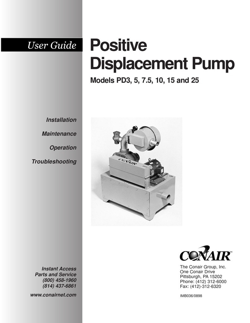
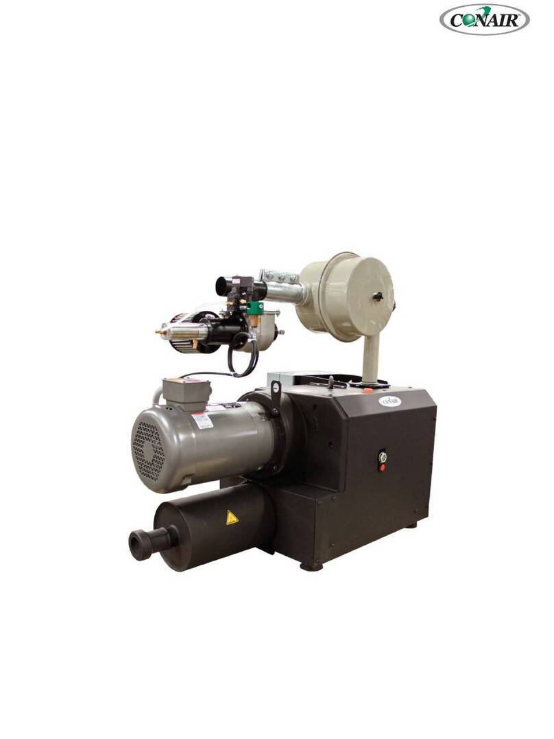
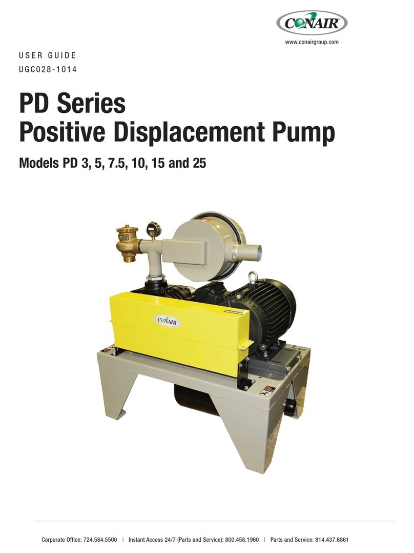
Conair HPD Series User manual

USER GUIDE
UGC036-0512
HPD Pump
Models HPD 5, 7.5, 10, 15, and 25
Corporate Office: 724.584.5500 lInstant Access 24/7 (Parts and Service): 800.458.1960 l Parts and Service: 814.437.6861
www.conairgroup.com

Please record your equipment’s
model and serial number(s) and
the date you received it in the
spaces provided.
It’s a good idea to record the model and serial number(s) of your equipment and
the date you received it in the User Guide. Our service department uses this infor-
mation, along with the manual number, to provide help for the specific equipment
you installed.
Please keep this User Guide and all manuals, engineering prints and parts lists
together for documentation of your equipment.
Date:
Manual Number: UGC036-0512
Serial Number(s):
Model Number(s):
DISCLAIMER: The Conair Group, Inc., shall not be liable for errors contained in this User Guide or
for incidental, consequential damages in connection with the furnishing, performance or use of
this information. Conair makes no warranty of any kind with regard to this information, including,
but not limited to the implied warranties of merchantability and fitness for a particular purpose.
Copyright 2012 l The Conair Group l All rights reserved

Table of Contents l i
Table of Contents
1Introduction
Purpose of the user guide . . . . . . . . . . . . . . . . . . . . . . . . . . . . . . . . 1-2
How the guide is organized . . . . . . . . . . . . . . . . . . . . . . . . . . . . . . 1-2
Using the HPD Pumps . . . . . . . . . . . . . . . . . . . . . . . . . . . . . . . . . . . 1-3
Your responsibilities as a user. . . . . . . . . . . . . . . . . . . . . . . . . . . . . 1-3
ATTENTION: Read this so no one gets hurt . . . . . . . . . . . . . . . . . . . 1-4
2-1 Description
What is the HPD Pump? . . . . . . . . . . . . . . . . . . . . . . . . . . . . . . . . . .2-2
Typical accessories and options . . . . . . . . . . . . . . . . . . . . . . . . . . . .2-2
Specifications: HPD Pumps . . . . . . . . . . . . . . . . . . . . . . . . . . . . . . . 2-3
3-1 Installation
Unpacking the boxes . . . . . . . . . . . . . . . . . . . . . . . . . . . . . . . . . . . 3-2
Preparing for installation . . . . . . . . . . . . . . . . . . . . . . . . . . . . . . . . . 3-2
Installing the pump . . . . . . . . . . . . . . . . . . . . . . . . . . . . . . . . . . . . . 3-3
Checking rotation . . . . . . . . . . . . . . . . . . . . . . . . . . . . . . . . . . . . . . 3-4
4-1 Maintenance
Preventative maintenance checklist . . . . . . . . . . . . . . . . . . . . . . . . 4-2
Inspect the idle mode/relief valve . . . . . . . . . . . . . . . . . . . . . . . . . . 4-3
Cleaning the dust collector filter . . . . . . . . . . . . . . . . . . . . . . . . . . . 4-3
Cleaning the idle mode/relief valve . . . . . . . . . . . . . . . . . . . . . . . . . 4-4
Readjusting the idle mode/relief valve. . . . . . . . . . . . . . . . . . . . . . . 4-5
Cleaning the precooler coils (optional). . . . . . . . . . . . . . . . . . . . . . . 4-6

5-1 Troubleshooting
Before you begin troubleshooting . . . . . . . . . . . . . . . . . . . . . . . . . . 5-2
A few words of caution . . . . . . . . . . . . . . . . . . . . . . . . . . . . . . . . . 5-2
Troubleshooting. . . . . . . . . . . . . . . . . . . . . . . . . . . . . . . . . . . . . . . . 5-3
AAppendix
We’re here to help . . . . . . . . . . . . . . . . . . . . . . . . . . . . . . . . . . . . . A-2
How to contact customer service . . . . . . . . . . . . . . . . . . . . . . . . . . A-2
Before you call... . . . . . . . . . . . . . . . . . . . . . . . . . . . . . . . . . . . . . . A-2
Equipment guarantee . . . . . . . . . . . . . . . . . . . . . . . . . . . . . . . . . . A-3
Performance warranty . . . . . . . . . . . . . . . . . . . . . . . . . . . . . . . . . . A-3
ii l Table of Contents

Introduction
Purpose of the user guide. . . . . . . . . . . . . . 1-2
How the guide is organized. . . . . . . . . . . . . 1-2
Using the HPD Pumps. . . . . . . . . . . . . . . . . 1-3
Your responsibilities as a user. . . . . . . . . . . 1-3
ATTENTION: Read this so no one gets hurt . . . 1-4
SECTION
1
Introduction l 1-1
1
Introduction

✐
Purpose of the User Guide
This User Guide describes the Conair HPD Pump and explains step-by-
step how to install, operate, maintain and repair this equipment.
Before installing this product, please take a few moments to read the User
Guide and review the diagrams and safety information in the instruction
packet. You also should review manuals covering associated equipment in
your system. This review won’t take long, and it could save you valuable
installation and operating time later.
How the Guide is Organized
Symbols have been used to help organize the User Guide and call your
attention to important information regarding safe installation and operation.
Symbols within triangles warn of conditions that could be hazardous to users or
could damage equipment. Read and take precautions before proceeding.
Numbers indicate tasks or steps to be performed by the user.
A diamond indicates the equipment’s response to an action performed by the user.
An open box marks items in a checklist.
A circle marks items in a list.
Indicates a tip. A tip is used to provide you with a suggestion that will help you with
the maintenance and the operation of this equipment.
Indicates a note. A note is used to provide additional information about the steps
you are following throughout the manual.
1
◆
❒
•
✒
1-2 l Introduction

Introduction l 1-3
Using the HPD Pumps
Each HPD Pump is designed to work within a central vacuum system
consisting of:
• Vacuum Receiver(s)
• Central Loading Control(s)
• Dust Collector
Separate instructions are provided for these devices and should be referred to as
needed to fully understand the operation of the entire system.
Your Responsibility as a User
You must be familiar with all safety procedures concerning installation, opera-
tion and maintenance of this equipment. Responsible safety procedures include:
•Thorough review of this User Guide, paying particular attention
to hazard warnings, appendices and related diagrams.
•Thorough review of the equipment itself, with careful attention
to voltage sources, intended use and warning labels.
•Thorough review of instruction manuals for associated equipment.
•Step-by-step adherence to instructions outlined in this User Guide.
1
Introduction

ATTENTION:
Read this so no one gets hurt
We design equipment with the user’s safety in mind. You can avoid the potential
hazards identified on this machine by following the procedures outlined below and
elsewhere in the User Guide.
WARNING: Improper installation, operation, or
servicing may result in equipment damage or
personal injury.
This equipment should be installed, adjusted, and serviced by qualified
technicians who are familiar with the construction, operation, and
potential hazards of this type of machine.
All wiring, disconnects, and fuses should be installed by qualified
electrical technicians in accordance with electrical codes in your
region. Always maintain a safe ground. Do not operate the equipment at
power levels other than what is specified on the machine serial tag and
data plate.
WARNING: Voltage hazard
This equipment is powered by three phase power, as specified on the
machine serial tag and data plate. See separate loading control
manual for control voltage requirements.
A properly sized conductive ground wire from the incoming control
wiring must be connected to the ground terminal inside the electrical
enclosure. Improper grounding can result in severe personal injury and
erratic machine operation.
Always disconnect and lock out the incoming main power and control
sources before opening the electrical enclosure or performing non-
standard operating procedures, such as routine maintenance. Only
qualified personnel should perform troubleshooting procedures that
require access to the electrical enclosure while power is on.
1-4 l Introduction

Description
What is the HPD Pump? . . . . . . . . . . . . . . . 2-2
Typical accessories and options. . . . . . . . . . 2-3
Specifications: HPD Pumps . . . . . . . . . . . . . 2-4
SECTION
2
2
Description
Description l 2-1

2-2 l Description
What is the HPD Pump?
Conair HPD Pumps are designed for long distance, high-volume material convey-
ing applications.
Each model has a powerful, rotating lobe-type blower, protected by a vacuum
relief valve (factory-set to 12 in. Hg) and belt driven by a three-phase motor with
magnetic starter and overload protection. An integrated pump protection filter is
included and all components are mounted on a rugged frame, housing an integrat-
ed exhaust muffler.
exhaust muffler
pump inlet
filter
optional pre-
cooler
idle mode/
relief valve
lobe type blower
motor
belt
guard

Typical Accessories and Options
Vacuum pumps traditionally work directly with dust collectors, cyclones or other filters that are
designed to remove plastic dust from the incoming air line to prevent contaminants from circulating
through the vacuum pump. In some cases, operation of the pump without a dust collection system
can create pump damage or a hazardous condition resulting from flammable or low melt-point plas-
tic material being exposed to the elevated operating temperatures of the pump.
Each HPD model includes a combination vacuum relief/idle mode valve. The valve allows the vacu-
um pump to remain operating for a period of time after the run signal from the loading control is
interrupted. This can greatly lengthen pump life by eliminating rapid start/stop cycles common to
many vacuum loading systems. Instead of shutting down, the pump continues to run for a minimum
of five minutes while vacuum pressure is relieved through a compressed air-operated valve that
bleeds ambient air into the vacuum inlet line of the pump. A clean compressed air source must be
provided to the valve solenoid for it to operate.
An optional air cooler option may be easily integrated into the assembly to reduce the temperature of
conveying air entering the pump for conveying applications that move heated materials.
Description l 2-3
Central
Vacuum Line
Material
Inlet
Material
Receivers
Receiving
Hoppers
Positive
Displacement
Vacuum Pump
Cyclone
2
Description

2-4 l Description
TPCX056-0512
MODEL HPD5 HPD7.5 HPD10 HPD15 HPD25
Motor type* TEFC TEFC TEFC TEFC TEFC
Performance characteristics
Horsepower 5 7.5 10 15 25
Standard CFM at material
pickup point @ 10" Hg 76.6 121.2 154.5 201.1 346.2
Average sound level (dbA)
@ 8", 10" and 12" Hg 81.0 82.5 83.6 82.8 86.1
Pump inlet filter area 53 ft2{5.0 m2}
Dimensions inches {mm}
Standard inlet size (OD) 1.75 {44} 2.25 {57} 2.5 {64} 3.0 {76} 4.0 {102}
Exhaust line size (NPT) 2.50 2.50 4.00 4.00 4.00
A - Height 53.5 {1359} 53.5 {1359} 81 {2057} 81 {2057} 82 {2083}
B - Width 46 {1168} 48 {1219} 50 {1270} 50 {1270} 55 {1397}
C - Depth 22 {559} 22 {559} 23.5 {597} 26 {660} 29 {737}
D - Vacuum inlet height 37 {940} 37 {940} 43.5 {1105} 43.5 {1105} 44.5 {1130}
A - Height w/precooler
†
60 {1524} 60 {1524} 81 {2057} 81 {2057} 82 {2083}
B - Width w/precooler
†
46 {1168} 48 {1219} 50 {1270} 50 {1270} 55 {1397}
C - Depth w/precooler
†
22 {559} 22 {559} 23.5 {597} 26 {660} 29 {737}
D - Vacuum inlet
height w/precooler
†
49 {1245} 49 {1245} 56 {1422} 56 {1422} 57 {1448}
Weight lb {kg}
Shipping weight 510 {231} 600 {272} 840 {381} 950 {431} 1200 {544}
Voltage Full load amps
240V/3 phase/60 hz 12 18.8 28 39 59
480V/3 phase/60 hz 6 9.4 14 19.5 29.5
575V/3 phase/50 hz 4.8 7.5 10.7 16 27
Optional precooler requirements
†
Water temperature‡45°- 85°F {7°- 29°C}
Water flow 3 gal/min {11.4 l/min}
Connections (NPT) 3/4 inch
A
C
B
D
SPECIFICATION NOTES:
*Energy-saving, high-efficiency motors are
also available.
†Precooler is an option.
‡
Water temperatures above or below the
recommended levels may affect pump
performance. Tower, chiller, or municipal
water sources can be used.
These tables define standard configura-
tions only. Specifications can change with-
out notice. Contact a Conair representative
for the most current information.
Note that on HPD5 and HPD7.5
models, the pump inlet filter is the
tallest point on the unit. On the
larger models, the exhaust muffler
is the tallest point on the unit. The
drawing below represents the HPD7.5
model.
Specifications

Installation l 3-1
Installation
Unpacking the boxes . . . . . . . . . . . . . . . . . 3-2
Preparing for installation . . . . . . . . . . . . . . 3-2
Installing the pump . . . . . . . . . . . . . . . . . . 3-3
Checking rotation . . . . . . . . . . . . . . . . . . . 3-4
SECTION
3
3
Installation

3-2 l Installation
Unpacking the Boxes
HPD Pumps are typically shipped bolted to a pallet and either enclosed by a box or
simply wrapped in protective plastic sheeting.
1Carefully remove the box or wrap and unbolt the unit from the shipping
pallet. When unpacking, make sure that all packing material is completely
removed from the pump, paying special attention to the inlet and outlet tubes
and crevice areas, to prevent potential damage caused by the packing materials
during the heat and suction of the pump’s operation.
2Once the pump is unbolted from the pallet, carefully move the pump using
a fork truck, crane or other lifting device. Use caution as the pump is trans-
ferred off the pallet and into the desired location for installation.
Preparing for Installation
The pump should be located in a protected, indoor location. Three phase power
will be required and a fused disconnect switch (not included) is required near the
pump. For use of the idle mode valve, compressed air will also be required near
the pump. Tubing connections to the pump are typically made with a flex hose to
allow easy connections.
Securing the pump to the floor with bolts is not strictly required, but is recom-
mended to prevent the minimal motion that could occur as the pump ages or in the
event of malfunction caused by contamination of the air stream.
The pump will only require minimal maintenance, but should still be located
where it is accessible and where its vacuum gauge is easily read by set-up and
operation personnel.
WARNING: You are
responsible for the
structural integrity of
this installation.

INSTALLATION AND
OPERATION NOTE: The
pump inlet is equipped
with a vacuum relief valve
to prevent the vacuum
from exceeding 12 in. Hg.
Excessive vacuum will
reduce the life of the
pump and can destroy it.
For special applications
requiring a higher vacuum
level or installation above
1500 ft elevation, consult
Conair service.
Central
Vacuum Line
Material
Inlet
Material
Receivers
Receiving
Hoppers
Positive
Displacement
Vacuum Pump
Cyclone
Installing the pump
1Use a fork truck to carefully move the pump into its operating location.
2Use care in orienting the pump for easy access to its pump starter and clearance
for the opening of its lid and allowing easy visibility of its vacuum gauge.
3Note the inlet and outlet of the pump. Generally, the outlet will simply exhaust
conveying air out of the muffler, but it may also be plumbed outside if desired, as
long as the exhaust line expands the size of the tube as it follows its path to
exhaust. The inlet stub will be connected to the dust collector or cyclone of the
system.
4The use of flex hose for pump connections is recommended, to allow easy
movement or service, if needed. Line up and coordinate all connections to allow
for easy connections, but wait until pump rotation has been established (and cor-
rected, if need be) before completing installation.
5Connect the dust collector or cyclone vacuum outlet to the pump inlet.
6Tighten all coupling bolts evenly. Tubing must not put a strain on the inlet or
outlet of the pump connections or eventual leaks will occur.
7Maintain an air space all around the pump for ventilation. Do not block or
cover any portion of the cooling fins that would prevent free air movement or
reduce cooling effectiveness.
8Connect power. Refer to the accompanying wiring diagram for connection of the
main power supply and the conveying control circuit. IMPORTANT: You must
provide a wall-mounted disconnect for three-phase electrical connection.
Incoming voltage and current must match the electrical specifications on the
pump data plate and serial tag.
Installation l 3-3
WARNING: This equipment
should be installed, adjusted,
and serviced by qualified tech-
nical personnel who are famil-
iar with the construction, oper-
ation and potential hazards of
this type of machine. All wiring,
disconnects and fuses should
be installed by qualified electri-
cal technicians in accordance
with electrical codes in your
region. Always maintain a safe
ground. Do not operate the
equipment at power levels
other than what is specified on
the the machine serial tag and
data plate.
3
Installation

3-4 l Installation
Checking Rotation
Upon initial start-up, but before normal operation, the HPD Pump must be checked
for proper rotation.
1 Set the loading controls to a minimal operating cycle (very low load time
setting of a single receiver, see separate loading control manual) and check the
pump with no vacuum or exhaust tubing or flex hose installed.
2Double-check air flow to confirm actual flow direction. If air is exiting from
the filter inlet, see step 3. If direction is OK, proceed.
3If direction is backwards, disconnect power and change any two of the three
phase leads coming into the pump starter. Upon confirming proper rotation,
reconnect power and complete the tubing installation for operation.
The HPD Pumps operate in response to signals provided from a loading control,
located elsewhere, and wired to the pump starter or the Transformer/Idle Mode
Control. Once properly installed, the pump should respond to signals from the
loading system and run according to the Idle Mode timer (if used) and the loading
control. Operation (on-time, etc) is determined solely by the loading and Idle
Mode Control Systems. The only change to operation that can occur within the
pump assembly itself is a motor overload within the pump starter or a malfunction.
If this occurs, see Troubleshooting section.
WARNING: This equipment should be installed, adjusted, and serviced by qualified
technical personnel who are familiar with the construction, operation and potential
hazards of this type of machine. All wiring, disconnects and fuses should be installed
by qualified electrical technicians in accordance with electrical codes in your region.
Always maintain a safe ground. Do not operate the equipment at power levels other
than what is specified on the the machine serial tag and data plate.
CAUTION: Never place your
hand directly over the inlet or
the exhaust.

Maintenance
Preventative maintenance checklist . . . . . . . 4-2
Inspecting the idle mode/relief valve . . . . . . 4-3
Cleaning the dust collector filter . . . . . . . . . 4-3
Cleaning idle mode/relief valve . . . . . . . . . . 4-4
Readjusting the idle mode/relief valve . . . . . 4-5
Cleaning the precooler coils . . . . . . . . . . . . 4-6
SECTION
4
Maintenance
4
Maintenance l 4-1

Preventative Maintenance Schedule
To maintain the best performance, you should follow the maintenance recommendations outlined
here and in any included manuals from component manufacturers.
●Weekly, or as often as needed
❒Check and clean the pump inlet filter.
An inlet filter has been provided to protect the pump from solid material that can enter and
damage the pump impellers. Material can enter the vacuum line if a receiver filter is improp-
erly installed or if if has a hole in it. Replace the pump inlet filter if it is torn or worn.
❒Check all V/belts.
The V/belts have a tendency to stretch, so an adjustable motor base is provided. Keep belts
tight to prevent slippage and wear. Do not use belt dressings.
●Every 500 hours of operation
❒Grease the pump.
Use No. 2 bearing grease or the equivalent. Refer to manuals from the component manufac-
turer for additional information and instructions.
●Every 1500 hours of operation
❒Change the oil.
The vacuum pump has been filled with the proper oil and tested by Conair before shipment.
Even so, this oil should be changed periodically. Use synthectic viscosity 220 or 320 or an
equivalent oil.
●Every three months
❒Check motor bearings and grease, if necessary.
The motor is equipped with double-shielded ball bearings having sufficient grease to last
indefinitely under normal service. But if the motor is used constantly in dirty, wet or corro-
sive atmospheres, you should add 1/4 oz. of grease per bearing every three months. Use a
quality, rust-inhibiting, polyure-based grease such as a NLGI #2 premium grade microgel
grease with 250°F {121°C}service temperature and moisture resistance and good mechani-
cal stability. Shell Darina EP NLGI Grade 2 is an example of this. Refer to the motor man-
ual for additional instructions.
●Every six months
❒ Check the idle mode/relief valve for proper operation.
The idle mode/relief valve is designed to protect the pump from damage if the conveying
line becomes clogged or obstructed.
4-2 l Maintenance

Inspect the idle mode/relief valve
The idle mode/relief valve is designed to protect
the pump from damage if the conveying line
becomes clogged or obstructed. To check the
valve:
1Partially obstruct the inlet by using a rigid
flat plate and slide it across the opening until
12 inches Hg registers on the gauge. Do NOT
completely block the inlet. The relief valve
should open at approximately 12 inches Hg.
Do not exceed 15 inches Hg. If the valve does
not release at or below 15 inches Hg, replace
or adjust the valve.
Note: Gauges should be
checked/calibrated every
12 months.
✐
Maintenance l 4-3
CAUTION: Hot sur-
faces. Always protect
yourself from hot sur-
faces inside and outside
the pump.
Cleaning the Pump Inlet Filter
WARNING: High voltage. Always stop the pump, disconnect and lock out the
main power source before troubleshooting or performing repairs.
Clogged filters reduce air flow and pump efficiency. Cleaning frequency
depends on how much material you process
and how dusty or full of fines it is.
1Remove the hand knob and pull the filter
lid off.
2Remove the filter hand knob, then
remove the filter.
3Clean the filter by laying it on its side and
gently tapping it on the floor. Replace
damaged, worn, or clogged filters.
4Remove any dust which may have accu-
mulated in the pump inlet filter housing.
5Reverse the procedure to reinstall the
dust collector filter. Ensure that the lid gas-
ket is in place and in good condition.
CAUTION: Wear eye
protection. If you use
compressed air to clean
equipment, you must
wear eye protection and
observe all OSHA and
other safety regulations
pertaining to the use of
compressed air.
CAUTION: Hot sur-
faces. Always protect
yourself from hot sur-
faces inside and outside
the pump.
4
Maintenance

4-4 l Maintenance
Cleaning the Idle Mode/Relief valve
1Stop the vacuum pump, disconnect and lockout the main power to the pump.
WARNING: High voltage. Always stop the pump, disconnect and lock out the main power
source before troubleshooting or performing repairs.
2Thoroughly inspect the idle
mode/relief valve. Check inside
and out for any signs of contamina-
tion, residue or other foreign sub-
stances that may potentially block
the motion of the internal, spring
loaded valve plate.
3Clean the inner components of
the valve. Use a cleaning agent
that will dissolve any plasticizer or
oily build-up on the surfaces of the
idle mode/relief valve. Be sure to
clean between the valve plate and the valve seal. Spray the cleaning agent into the valve opening
and then flush out. The valve may require disassembly to reach critical areas.
IMPORTANT: If a valve can not be cleaned adequately it should be replaced to prevent malfunction or a
potentially hazardous condition due to inadequate vacuum relief.
4Reassemble the valve and re-adjust to the proper vacuum setting (see instructions for
adjusting the idle mode/relief valve.)
CAUTION: Wear eye protection. If you use compressed air to clean the equipment, you
must wear eye protection and observe all OSHA and other safety regulations pertaining
to the use of compressed air.
This manual suits for next models
5
Table of contents
Other Conair Water Pump manuals
Popular Water Pump manuals by other brands

Altrad
Altrad BELLE WPX 3/30 Operator's manual

salmson
salmson ALTI-HE 2G Installation and starting instructions

Becker
Becker SV 5.690 operating instructions

Wilo
Wilo Padus PRO Series Installation and operating instructions

Vito Agro
Vito Agro VIBAL550A instruction manual

vacuubrand
vacuubrand VACUU-PURE Assembly instructions

Utilitech
Utilitech 148012 manual

esotec
esotec pro Fountain 300-LED operating manual

MULTIQUIP
MULTIQUIP QP2TZ Operation and parts manual

Porto-Power
Porto-Power Blackhawk Automotive B93601A Operating instructions & parts manual

Simer
Simer 3325E owner's manual

Gast
Gast 81R Series Operation & maintenance manual