Concept Pro AIR701/IRH User manual

AIR701/IRH
Weatherproof Zoom Colour/Mono
IR Camera
USER MANUAL
TECHNOLOGY
ADVANCED INFRARED
Powered by
All manuals and user guides at all-guides.com
all-guides.com

PACKING CONTENTS
X1
WALL SCREW
X4
The Concept Pro AIR701/IRH is a weatherproof IR camera, suitable for
monitoring areas in hostile conditions and in low light.
MOUNTING
DRAWING PAPER
X1
ALLEN KEY
X1
FIXING PLATE X2
2
31
7
1 Fixing Bolt for Sunvisor
2. Photo Sensor
3. IR LED
4. Sunvisor
5 Mounting Bracket
6 Bracket Adjustment
7 Service Video Outputt
FIXING PLATE
LOCATING SCREW X1
EASY FIT BNC CONNECTOR
X1
EASY FIT POWER CONNECTOR
X4
BRACKET/FIXING
PLATE SCREW
X1
OSD CABLE
(AIR4526HG / 4527HG / 5026HG
MODELS ONLY)
L
U
D
R
ENT
USER
MANUAL
X1
USER MANUAL
4
5
6
All manuals and user guides at all-guides.com

EASY FIT BNC CONNECTOR
1. This installation should be made by a qualified service person and should abide to all local
codes.
2. In order to prevent electronic shock and/or destroy waterproof seals, do not loosen any
screws on the camera body.
3. Adjust the sunshield cover to avoid exposure of direct sunlight on the lens.
4. Do not touch the front glass directly. If necessary, use a soft cloth moistened with alcohol to
wipe off dust or debris.
5. Avoid installation on a surface subjected to frequent vibration or shocks.
6. Do not operate the camera beyond its temperature range or power source ratings.
7. Should any damage or suspected damage occur, shutdown the power source, unplug and
contact your service provider.
8. Do not install the camera under unstable lighting conditions. Severe lighting change or
flicker can cause the camera to work improperly.
9. Never use the camera close to a gas or oil leak.
10. Do not disassemble the camera.
11. Do not drop the camera or subject the unit to physical shocks. Never keep the camera
face to strong light directly, this can damage the CCD.
12. Ensure all removable covers are replaced to protect the inner components.
13. Do not install near devices which emit a strong electro-magnetic field.
14. Use a dry or damp cloth only for cleaning.
PLEASE FOLLOW THE ABOVE CAUTIONS – FAILURE TO DO SO MAY
INVALIDATE THE WARRANTY OR CAUSE SERIOUS INJURY.
Remark: Changes or modifications not expressly approved by the manufacturer can
cause the camera to be damaged and become inoperable. This may invalidate the
user warranty.
CAUTION
All manuals and user guides at all-guides.com

1. This installation should be made by a qualified service person and should abide to all local
codes.
2. In order to prevent electronic shock and/or destroy waterproof seals, do not loosen any
screws on the camera body.
3. Adjust the sunshield cover to avoid exposure of direct sunlight on the lens.
4. Do not touch the front glass directly. If necessary, use a soft cloth moistened with alcohol to
wipe off dust or debris.
5. Avoid installation on a surface subjected to frequent vibration or shocks.
6. Do not operate the camera beyond its temperature range or power source ratings.
7. Should any damage or suspected damage occur, shutdown the power source, unplug and
contact your service provider.
8. Do not install the camera under unstable lighting conditions. Severe lighting change or
flicker can cause the camera to work improperly.
9. Never use the camera close to a gas or oil leak.
10. Do not disassemble the camera.
11. Do not drop the camera or subject the unit to physical shocks. Never keep the camera
face to strong light directly, this can damage the CCD.
12. Ensure all removable covers are replaced to protect the inner components.
13. Do not install near devices which emit a strong electro-magnetic field.
14. Use a dry or damp cloth only for cleaning.
PLEASE FOLLOW THE ABOVE CAUTIONS – FAILURE TO DO SO MAY
INVALIDATE THE WARRANTY OR CAUSE SERIOUS INJURY.
INSTALLATION
Important: Ensure all cautionary procedures are observed during installation.
It is recommended the camera is tested during the most demanding environmental conditions
such as low light or bright sunlight to ensure continuity of effective CCTV monitoring. You may
find the use of an ND filter helpful.
Use the supplied drill mounting
template to mark the spacing
for drilling.
Following drilling, securely
attach the bracket and
camera to the wall.
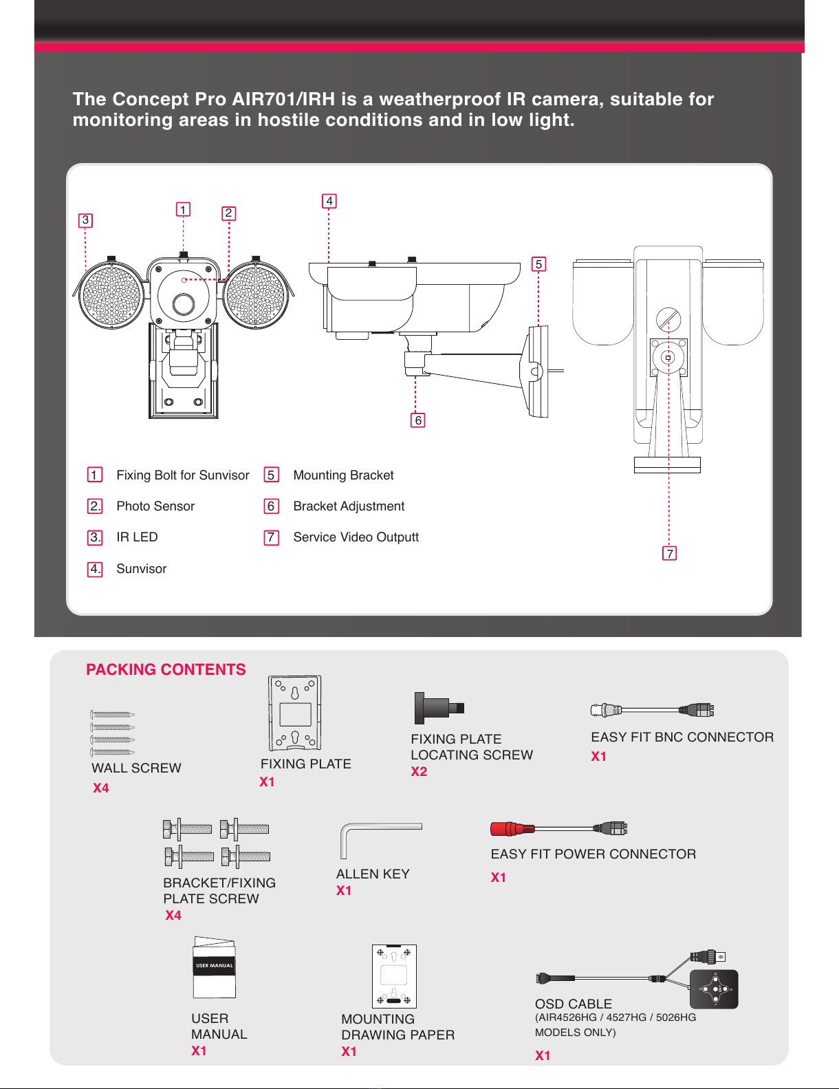
Remove the camera unit carefully from the box, reserving the accessory contents in a
safe place.
FIXING TO A WALL
POSITIONING
Point the Camera towards the
intended area to be monitored.
MOUNTING TEMPLATE
All manuals and user guides at all-guides.com

CONNECTION
BNC CONNECTOR
RS485 CONNECTOR
POWER CONNECTOR
Connect the video out port to your video cable
running to the monitoring recorder.
Check the power supply is of the correct level
and connect your power supply into the power
port on the Camera.
View the picture on a monitoring device to
check the power and video connection is
working properly.
Connect the RS485 to keyboard (if required)
When using the VA-KBDPRO+ for RS485 control
please use the command ‘Preset 95’ for entering
the menu and again for entering sub-menus
PSU
DVR CAM MENU SET PRESET
AUX/
SEARCH
RUN/
PANIC
PATTERN/
SETUP
PREV /
DISPLAY
NEXT /
SEQ
MON
CAM/DVR
ESC
ENTER
1 2 3
456
789
0
OPEN FAR WIDE
IRIS FOCUS ZOOM
CLOSE NEAR TELE
POWER Rx Tx
*
DVR AI CAM
ALM/ GROUP/ OFF/ ON/ VST/
Troubleshooting
Ensure all power and cable connections are correct with the Camera, DVR and Test monitor
or Telemetry devices if used.
Power Voltage Check - Remove the OSD cover to see if the green correct power LED is lit. If
there red LED is lit the power voltage is too high. If the yellow LED is lit the power voltage is
not high enough. If there are no LEDs lit there is no power getting to the camera
If all power and cable connections are correct and the camera picture can not be produced or
configured then contact your supplier for technical support.
All manuals and user guides at all-guides.com

ON SCREEN DISPLAY (OSD)
The power indicator LEDs display the power supply being fed into the camera and whether it
is too high, low or correct.
1. "PO": Red LED - Voltage is too high
2. "PN": Green LED - Voltage is correct
3. "PL": Yellow LED - Voltage is too low
4. Extra video out and OSD Connector - Attach your Video test monitor with the service video
cable enclosed in your camera box. The camera footage will appear on your test monitor
and zoom/focus adjustments can be carried out as the installation requires.
5. Camera ID Setup
ID number of camera is set using binary numbers.
The example is shown to the right shows ID 1
The Service Video Out panel contains a power indicator and test monitor connection for
ease of adjusting the camera settings during installation.
123
TEST MONITOR
OSD OUTPUT CABLE
L
U
D
R
ENT
1) Press “U” to navigate upwards
2) Press “D” to navigate downwards
3) Press “L” to navigate left
4) Press “R” to navigate right
5) Press “ENT” to open menu/sub-menu
OSD Controller
L
U
D
R
ENT
PIN 1 2 3 4 5 6 7 8
ID Value 1 2 4 8 16 32 64 128
ON
12345678
POPN
PL
ON
12 3 4 5 678
4
5
All manuals and user guides at all-guides.com
all-guides.com

FOCUS
EXPOSURE
FOCUS FOCUS MODE
FOCUS DIST
ZOOM START
ZOOM END
ZOOM SPEED
REFRESH MODE
REFRESH TIME
INITIAL
AUTO
MANUAL
PUSH [PRESS ENT]
1CM ~ 3M
x001 ~ x027
x001 ~ x270
1 ~ 3
ON / OFF
[SET TIME]
OFF / ON
The power indicator LEDs display the power supply being fed into the camera and whether it
is too high, low or correct.
1. "PO": Red LED - Voltage is too high
2. "PN": Green LED - Voltage is correct
3. "PL": Yellow LED - Voltage is too low
4. Extra video out and OSD Connector - Attach your Video test monitor with the service video
cable enclosed in your camera box. The camera footage will appear on your test monitor
and zoom/focus adjustments can be carried out as the installation requires.
5. Camera ID Setup
ID number of camera is set using binary numbers.
The example is shown to the right shows ID 1
EXPOSURE AE MODE
SHUTTER
IRIS
AGC
BRIGHTNESS
FLICKERLESS
D.S.S.
INITIAL
AUTO / SHUT MAN / IRIS
MAN / AGC MAN
NORMAL / x125 ~ x10000
0 ~ 255
0 ~ 255
0 ~ 48
OFF / ON
OFF / FLD 2 ~ 128
OFF / ON
DAY / NIGHT
DAY / NIGHT AUTO
NIGHT
DAY
D&N MODE
DWELL TIME
INITIAL
D&N MODE
DWELL TIME
INITIAL
D&N MODE
DWELL TIME
INITIAL
AE / EXT D&N
1 ~ 10SEC
OFF / ON
AE / EXT D&N
1 ~ 10SEC
OFF / ON
AE / EXT D&N
1 ~ 10SEC
OFF / ON
All manuals and user guides at all-guides.com

BLC
WHITE BALANCE
WHITE BAL ATW
MANUAL
INDOOR
OUTDOOR
PUSH
RED CONT
BLUE CONT
[PRESS ENT]
0 ~ 255
0 ~ 255
BLC NORMAL / C1 / C2 / L1 / L2 / U1 / U2 / D1
/ D2 / R1 / R2
3D-DNR
3D-DNR OFF / LOW / MIDDLE / HIGH
All manuals and user guides at all-guides.com

GENERAL CAM ID
ID DISPLAY
CAM TITLE
LANGUAGE
PROTOCOL
BAUDRATE
VERSION
INITIAL
NOT USED
NOT USED
ON / OFF
ENG
NOT USED
NOT USED
OFF / ON
INITIAL
INITIAL OFF / ON
SPECIAL
SPECIAL D-EFFECT
SHARPNESS
FREEZE
COLOUR
MOTION
PRIVACY
INITIAL
OFF / V-FLIP / ROTATE / MIRROR
1 ~ 16
OFF / ON
ON / OFF
ZONE SELECT
ZONE STATE
SENSITIVITY
INITIAL
MASK NUMBER
MASK STATE
MASK COLOUR
TOP
BOTTOM
LEFT
RIGHT
INITIAL
OFF / ON
CENTRE / WHOLE /
UPPER / OUT
OFF / ON
1 ~ 15
OFF / ON
0 ~ 3
OFF / ON
GREY / BLACK /
WHITE / YELLOW
(SELECT SIZE)
(SELECT SIZE)
(SELECT SIZE)
(SELECT SIZE)
OFF / ON
GENERAL
All manuals and user guides at all-guides.com

BNC CONNECTOR
Troubleshooting
Ensure all power and cable connections are correct with the Camera, DVR and Test monitor
or Telemetry devices if used.
Power Voltage Check - Remove the OSD cover to see if the green correct power LED is lit. If
there red LED is lit the power voltage is too high. If the yellow LED is lit the power voltage is
not high enough. If there are no LEDs lit there is no power getting to the camera
If all power and cable connections are correct and the camera picture can not be produced or
configured then contact your supplier for technical support.
DIMENSIONS
302.2mm(11.89”)
40mm(1.57”)
85mm(3.35”)
97mm(3.85”)
All manuals and user guides at all-guides.com

300mm(11.81”)
319mm(12.56”)
219mm(8.62”)
All manuals and user guides at all-guides.com
all-guides.com

Design and specification are subject to change without notice.
AIR701/IRH
Twin IR Zoom Colour/Monochrome (Removable IR Cut Filter)
PAL
1/4 inch SONY Exview CCD
795(H)x596(V) 470K
752(H)x582(V) 440K
27x. F1.6(W) ~ 3.7(T) ( ± 7 %), f = 3.6 ~ 97.2 mm ( ± 7 %)
x10
580 TV Lines
0 Lux ( 220pcs IR LED ON)
Auto/Manual/Push
(H) 15.625 KHz (V) 50 Hz
2:1 Interlace
More than 50 dB
Normal / x125 ~ x10000
ATW, Manual, Indoor, Outdoor, Push
Normal / C1 / C2 / L1 / L2 / U1 / U2 / D1 / D2 / R1 / R2
Auto / 0 ~ 255
Off / Low / Middle / High
Off / Up to 128x
CVBS : 1.0Vp-p / 75Ω
RS-485
Pelco-D
DC12v ( ± 10%) AC 24v ( ±10%)
DC: 2000mA AC: 1400mA
75~80m (245.9~262.3ft) (Outdoor)
302.2mm (11.98") (W) x 219mm (8.62") (H) x 319mm (12.56") (D)
3.9kg
-30° to +60°
-10° to +40°
ITEM
Type
Signal System
Image Sensor
Total Pixels
Effective Pixels
Lens
Digital Zoom
Resolution
Min Illumination
Focus
Frequency
Scanning System
S/N ( Y signal )
Electronic Shutter Speed
White Balance
Back Light Comp.
Auto Gain Control
3D-DNR
DSS
Video Output
Communication
Protocol
Power Supply
Current Consumption (Max)
IR Effect Distance
Dimension
Weight (Product)
Storage Temperature
Operating Temperature
All manuals and user guides at all-guides.com

AIR30 Range
42 IR LEDs
Varifocal Lens Options
Service Video Output Option
On Screen Display Option
External Lens / Zoom Adjustments
202 x 85 x 118mm (WxHxD)
AIR15 Range
18 IR LEDs
420 TVL / 520 TVL Options
3.6mm / 6mm Fixed Lens Options
182 x 70 x 81mm (WxHxD)
AIR45 / 50 Range
60 IR LEDs
Varifocal Lens Options
Service Video Output Option
On Screen Display Option
External Lens / Zoom Adjustments
340 x 219 x 100mm (WxHxD)
Extend the IR range up to
80m with AIR-IR.
AIR CAMERA RANGE
All manuals and user guides at all-guides.com

All manuals and user guides at all-guides.com
Other manuals for AIR701/IRH
1
Table of contents
Other Concept Pro IP Camera manuals

Concept Pro
Concept Pro CBP6325EL-AHD2M User manual

Concept Pro
Concept Pro AIR3026-HD User manual

Concept Pro
Concept Pro CVP9328DNIR-AHD2M User manual

Concept Pro
Concept Pro VHSDIR-870EXT-IP User manual

Concept Pro
Concept Pro CVP9314DNIR-AHD User manual

Concept Pro
Concept Pro AIR2024-AHD Series User manual

Concept Pro
Concept Pro AIR3526-AHD User manual

Concept Pro
Concept Pro AIR701/IRH User manual

Concept Pro
Concept Pro CVP9328DNIR-AHD User manual

Concept Pro
Concept Pro AIR20NPC series User manual