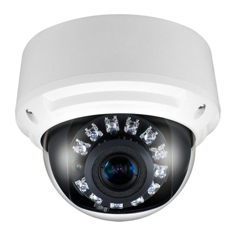
Concept Pro CBP6325EL-AHD2M User manual

AHD CAMERA QUICK START GUIDE
CBP6325EL-AHD2M
CBP6325IREL-AHD2M
CBP6325IREL-AHD5M
CBP6325IREL-AHD5M-Z
AHD Internal Dome Camera
QUICK START GUIDE
Technical Documents

AHD CAMERA QUICK START GUIDE
Packaging Contents
Technical Documents 4-in-1 AHD Camera x1 Silica Gel x1
Quick Start Guide x1 Fitting Screws x3
Mounting Template x1 Screw Anchors x3
DC12V/AC24V Power Input Cable x1
2. INSTALLATION
Important: Ensure all precautionary procedures are observed during installation.
It is recommended that the camera is tested in low light and harsh lighting conditions during
installation to ensure continuity of effective CCTV monitoring.
Open Packaging
Open packaging, remove camera, and set aside the included accessories.
Drill Mounting Holes
Attach the included mounting template to the desired
mounting surface (ceiling or wall). Ensure the surface can bear
the camera weight. Drill mounting holes and cable throughput
holes according to the template. Insert the included screw
anchors into the holes. Grip the side of the dome cover and
rotate to unlock and remove the dome cover. Note: the dome
cover is connected to the dome base with a safety leash.
Mount the Camera
Insert any required cables through the cable throughput
hole. Connect the cables to the appropriate terminal on the
camera. Position the camera over the mounting holes and
use the included fitting screws to affix the camera to the
mounting surface.
Adjust Camera Positioning
Adjust the camera lens so that it can monitor the desired area.
Confirm all connections are secure. Replace the dome cover
and twist to lock into position. It is recommended that silicon
is injected into the gap between the camera and mounting
surface for secure waterproofing.
1. CONTENTS
2
3
4
1
.
.
PAN
TILT
ROTATE
PAN
TILT
ROTATE
Note: Rotate the lens from the rear of the lens
gimbal where there are grip notches.

AHD CAMERA QUICK START GUIDE
3. Camera Configuration
Connection
1. Connect a DC12V/AC24V power supply adapter to the camera DC12V/AC24V power input. The
power input has reverse polarity protection. Note: only use a power supply adapter that matches the
camera’s rated power supply specifications.
2. Ensure the camera and power supply are properly grounded. If necessary, install a ground loop isolator
accessory.
3. Connect the camera BNC video output to a video monitoring device BNC video input, such as a
Concept Pro digital video recorder, with RG56/RG6 coaxial cable. Alternatively, connect CAT5E/CAT6
Ethernet cable to the UTP+/- Video Output terminals and change the video output on the camera
using the SW1 DIP switch shown on the diagram below.
4. For the best video quality, please follow the recommended cable guidelines below. Note that actual
transmission range will vary depending on the type and quality of cables/baluns used.
Maximum Cable Transmission Distance
Cable/Resolution 5MP 2MP
RG59 Coax 500m 500m
CAT5E Ethernet 200m 305m
CAT6 Ethernet 200m 305m
5. To assist in installation when using a video test monitor, the camera can be switched to standard
definition analogue output by pushing the OSD control button up for about five seconds or by using
the SW2 DIP switch shown on the diagram below (AHD2M models only). The camera can be returned
to AHD video output by pushing the OSD control button left for about five seconds or using the SW2
DIP switch shown on the diagram below (AHD2M models only).
Note: Actual transmission range will vary depending on type and quality of cables and baluns used.
PSU

AHD CAMERA QUICK START GUIDE
Built-in Control Board Functions
1. DC12V/AC24V Power Input. Note: Reverse polarity protected.
2. Video Format Selector (AHD/TVI/CVI/CVBS)
Note: Only AHD2M models have the Video Format Selector DIP switch. Motorised 5-megapixel
(AHD5M) models can be changed to a different video format via the OSD menu. Press the OSD
joystick button to open the OSD menu, then use the joystick to navigate to VIDEO SETTING
menu, select AHD/TVI/CVI/CVBS and resolution, then return, apply, and reboot.
Manual varifocal AHD5M models can be changed to a different video format by pressing and
holding the OSD joystick in the indicated direction for >5 seconds when the OSD menu is closed.
- Up: CVBS - Left: AHD - Right: TVI - Down: CVI
ON
HD TVI
1 2
ON
AHD
1 2
ON
ANALOGUE
1 2
ON
HD CVI
1 2
3. Video Output Type Selector (BNC Output/UTP Output)
1. SW1:1 ON & 2 OFF----BNC Video Output
2. SW1:1 OFF & 2 ON----UTP Video Output
Please ensure the DIP switch is set to either BNC or UTP Video Output. Failure to do so may result in
reduced signal strength and transmission distance.
4. 4-pin Terminal Block (Video Output/Power Output)
1. UTP VIDEO OUTPUT+ 2. UTP VIDEO OUTPUT- 3. GND 4. DC12V 100MA POWER OUTPUT
The DC12V Power Output may be used to directly provide power from the camera to auxiliary
equipment, such as alarm sensors, removing the need for a separate power adapter.
The maximum power output is DC12V 100mA.

AHD CAMERA QUICK START GUIDE
4. ON-SCREEN DISPLAY MENU
MAIN
LENS Lens Mode
EXPOSURE Exposure Settings
WHITE BAL White Balance Settings
BACKLIGHT Backlight Mode
DNR Digital Noise Reduction Settings
(OFF/LOW/MIDDLE/HIGH)
DAY & NIGHT Day & Night Settings
IMAGE Image Settings
SPECIAL System Settings
AF Auto Focus & Lens Settings
RESET Reset Settings
EXIT Close Menu
EXPOSURE
BRIGHTNESS Set image exposure brightness
value (0-20).
SHUTTER
AUTO: Automatically adjust shutter
speed (NORMAL/DEBLUR).
MANUAL: Manually adjust shutter
speed (1/25600, 1/12800, 1/6400,
1/3200, 1/1600, 1/800, 1/400,
1/200, 1/100, 1/50, 1/25).
FLICKER:
SENS-UP Adjust SENS-UP settings (OFF/X2/
X4/X8/X16/X32).
AGC Adjust automatic gain control
settings (0-20).
WHITE BALANCE
AUTO Automatically adjust image white
balance.
AUTOext White balance with auto-tracking.
PRESET Fixed white balance setting.
MANUAL
Manually adjust image white
balance.
C-TEMP: Colour temperature
(3000K/5000K/8000K)
R-GAIN: Red colour gain (0-20).
B-GAIN: Blue colour gain (0-20).
LENS MODE NORMAL:
DEBLUR:
LEVEL Set lens mode level (0-20).
AHD2M MENU STRUCTURE

AHD CAMERA QUICK START GUIDE
4. ON-SCREEN DISPLAY MENU
BACKLIGHT
WDR
Enter to
configure true
wide dynamic
range settings.
MODE
NORMAL: Apply
TWDR settings
across entire
image.
ROI: Configure
region of interest
for TWDR
settings.
ROI:
- WINDOW ZONE: Select ROI zone.
- WINDOW USE: Turn ON to
change zone position.
- H-POS: Set horizontal position.
- V-POS: Set vertical position.
- H-SIZE: Set horizontal size.
- V-SIZE: Set vertical size.
WEIGHT
Configure TWDR
level (LOW/
MIDDLE/HIGH).
BLC
Enter to
configure
backlight
compensation
settings.
H-POS Set horizontal
position.
V-POS Set vertical
position.
H-SIZE Set horizontal size.
V-SIZE Set vertical size.
HLC
Enter to
configure
highlight
compensation
settings.
MODE
ALL DAY: Apply
HLC settings
all day.
NIGHT ONLY:
Apply HLC
settings in B&W
mode only.
LEVEL Configure HLC
level (0-20).
OFF
Select to turn
backlight
control
options off.
AHD2M MENU STRUCTURE
DAY & NIGHT
MODE EXTERN/AUTO/COLOUR/B/W
DELAY Select Day/Night trigger delay
(0-20).
D>N LEVEL Select sensitivity for transitioning
from Day to Night mode (0-20).
N>D LEVEL Select sensitivity for transitioning
from Night to Day mode (0-20).
IMAGE
SHARPNESS MANUAL: Manually set static
image sharpness level (0-20).
COLOUR GAIN MANUAL: Manually set static
image colour gain level (0-20).
FREEZE Select ON to freeze the current live
video image.
FLIP
OFF: Default image view.
H-INV: Flip image horizontally.
V-INV: Flip image verticially.
HV-INV: Completely flip image.
ACE Adjust edge brightness
compensation settings.
GAMMA Adjust gamma settings.

AHD CAMERA QUICK START GUIDE
4. ON-SCREEN DISPLAY MENU
AHD2M MENU STRUCTURE
AF FOCUS MODE
SEMI: Camera will auto focus and
can be manually adjusted.
MANUAL: Camera can only be
manually focused.
LENS ADJ Reset lens (motorised models only).
SPECIAL
SYSTEM Enter to configure
system settings.
OUTPUT Displays current video resolution
output (1080p).
COLOUR
SPACE
Colour format (HD-CbCr/YUV/
SD-CbCr).
CVBS Select video format (PAL/NTSC).
FRAME RATE Displays current video frame rate
(25/30FPS).
BLACK
LEVEL Adjust image black levels.
VERSION Displays current camera firmware
version.
LANGUAGE Select language (English, Chinese, Japanese, Korea, German).
PRIVACY
ON: Configure custom
built-in privacy mask
area.
OFF: Do not use privacy
masking.
ZONE NUM Select privacy mask number.
ZONE DISP
ON: Privacy mask displays
over video.
OFF: Privacy mask does not
display over video.
H-POS Set horizontal position.
V-POS Set vertical position.
H-SIZE Set horizontal size.
V-SIZE Set vertical size.
Y LEVEL Set mask area size.
CB LEVEL
Set mask area colour (Y) when
colour format YUV selected in
Colour Space.
CR LEVEL
Set mask area colour (U) when
colour format YUV selected in
Colour Space.
TRANS Set privacy mask transparency
level.
MOTION
ON: Configure custom
built-in motion detection
area.
OFF: Do not use motion
detection.
SENSITIVITY Set motion detection sensitivity
level (1-10).
WINDOW
TONE
Select motion area display
settings.
WINDOW
USE Select to use motion area.
WINDOW
ZONE Set motion area size.
DET H-POS Set horizontal position.
DET V-POS Set vertical position.
DET H-SIZE Set horizontal size.
DET V-SIZE Set vertical size.
ALARM Set motion alarm setting.
SHADING Adjust shadow
homogenization. WEIGHT Set shadow weight.
COLOUR
BAR
ON: Change video screen to colour bar test.
OFF: Standard camera view.

AHD CAMERA QUICK START GUIDE
4. ON-SCREEN DISPLAY MENU
AWB - WHITE BALANCE
IMAGE ENHANCE
VIDEO SETTINGS
DAY/NIGHT
MODE PRO/GREY WORLD
RGAIN RED GAIN: 0-100
BGAIN BLUE GAIN: 0-100
CONTRAST
AUTO: Automacally adjust image contrast
depending upon environment.
MANUAL: Manually set stac image contrast
level (0-20).
SHARPNESS
AUTO: Automacally adjust image sharpness
depending upon environment.
MANUAL: Manually set stac image sharpness
level (0-20).
SATURATE
AUTO: Automacally adjust image saturaon
depending upon environment.
MANUAL: Manually set stac image saturaon
level (0-20).
3DNR
AUTO: Automacally adjust image 3D digital
noise reducon depending upon environment.
MANUAL: Manually set stac image 3D digital
noise reducon level (0-20).
HD
AHD: Select for AHD video format
(5MP@20/12.5FPS, 4MP@30/25/15FPS, 2MP@30/25FPS)
TVI: Select for TVI video format
(5MP@20/12.5FPS, 4MP@30/25FPS, 2MP@30/25FPS)
CVI: Select for CVI video format
(4MP@30/25FPS, 2MP@30/25FPS)
CVBS: Select for SD video format
(960H@30/25FPS; PAL/NTSC)
STANDARD Select resoluon/frame rate opon.
APPLY&REBOOT Click to apply video seng and reboot
camera.
MODE EXT/AUTO/COLOUR/B&W
AHD5M MENU STRUCTURE

AHD CAMERA QUICK START GUIDE
5. Special Features
True Wide Dynamic Range
These camera models support True Wide Dynamic Range (TWDR), which significantly increases overall
image quality in scenes where there is high contrast between dark and bright areas.
For example, TWDR allows for a camera installed inside monitoring an entrance to not only monitor the
indoor area but also the exterior.
True Wide Dynamic Range can be configured from the following OSD menus:
AHD2M Models: Main Menu->Backlight->WDR
AHD5M Models: Main Menu->WDR (On/Off)
After selecting the desired option, select SAVE&EXIT.
Variable Bit Rate Recording on Concept Pro Analogue Recorders
When this camera is used with a Concept Pro digital video recorder product, image quality can be
balanced with recording time by selecting the Variable Bit Rate (VBR) bit rate control option from the DVR
Record Setup menu. When VBR is enabled, the system will automatically use the highest image quality
for scenes with motion and revert to lower image quality settings when no motion or other events are
occurring. This can save a significant amount of storage space and extend the system recording time.
Configure the Concept Pro DVR to use VBR by following the steps below:
From <RECORD SETUP>, select <OPERATION MODE>.
Use the directional and [ENTER] buttons on the remote control or the mouse to set <RECORDING
CONFIGURATION MODE> to <AUTO CONFIGURATION> or <MANUAL CONFIGURATION>.
Set the recording options for each selected recording mode.
Select VBR under <BIT RATE CONTROL>.
To save the configuration, click <APPLY> on the bottom of the screen.
When finished, press the [EXIT] button on the remote control or click <CLOSE> on the bottom of the
screen to return to the previous menu.
6. Troubleshooting
- Ensure all power and cable connections are correct between the camera and recorder.
- If all power and cable connections are correct and the camera picture does not appear, contact your
supplier for technical support.
- Ensure that the digital video recorder supports the camera’s specified resolution and format. Try
switching the camera to CVBS format with the DIP switch to confirm the image appears on the DVR,
then switch the camera to a supported format and resolution.

AHD CAMERA QUICK START GUIDE
7. Caution
Safety Precautions
1. Carefully read all instructions and warnings prior to using this device.
2.
Installation should be made by qualified service personnel and should adhere to all local codes.
3. Do not install this device near water or in excessively humid conditions.
4. Do not install this device near any heat sources such as radiators or stoves.
5. Do not install this device near flammable substances such as gas or oil.
6. Do not install this device in environments with unstable lighting conditions.
Severe lighting changes or flickering can cause the camera to malfunction.
7. Do not install this device in environments where it is directly facing a strong light source.
8. Do not install this device near devices which emit a strong electro-magnetic field.
9. Do not install this device on a surface subjected to frequent vibration or shocks.
10. Do not operate this device beyond its specified temperature, humidity, and power source
rating ranges.
11. Do not disassemble the camera.
12. Should any damage or suspected occur, shutdown the power source, unplug the camera,
and contact your service provider. Do not attempt to repair the device.
13. Ensure any cable is not stepped on or twisted. Use the appropriate cable and wiring best
practices for the installation environment.
14. Unplug the power source from the device during installation or maintenance.
15. Ensure proper grounding techniques are used when installing the device in areas with
voltage fluctuations or frequent lightning strikes.
16. Only use a dry cloth for cleaning.
17. Unplug the device when it is unused for long periods of time.
18. Only use accessories or attachments specified by the manufacturer.
CAUTION
PLEASE FOLLOW THE ABOVE PRECAUTIONS –
FAILURE TO DO SO MAY INVALIDATE THE WARRANTY OR CAUSE SERIOUS INJURY.
Note: Changes or modifications not expressly approved by the manufacturer can cause the
camera to be damaged and become inoperable. This may invalidate the user warranty.

AHD CAMERA QUICK START GUIDE
8. Dimensions
All measurements are in mm.

Design and specification are subject to change without notice.
This manual suits for next models
3
Table of contents
Other Concept Pro IP Camera manuals

Concept Pro
Concept Pro AIR701/IRH User manual

Concept Pro
Concept Pro CVP9328DNIR-AHD User manual

Concept Pro
Concept Pro AIR3526-AHD User manual

Concept Pro
Concept Pro VHSDIR-870EXT-IP User manual

Concept Pro
Concept Pro AIR45 IP4M Series User manual

Concept Pro
Concept Pro CVP9314DNIR-AHD User manual

Concept Pro
Concept Pro AIR2024-AHD Series User manual

Concept Pro
Concept Pro AIR3026-HD User manual

Concept Pro
Concept Pro AIR20NPC series User manual

Concept Pro
Concept Pro AIR701/IRH User manual