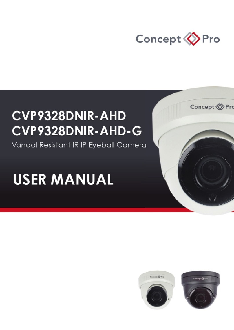
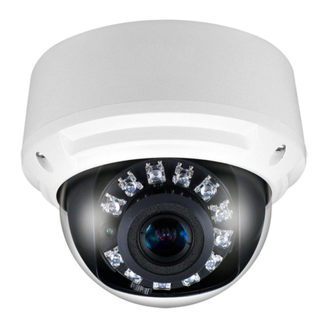
Concept Pro CVP9314DNIR-AHD User manual

CVP9314DNIR-AHD
Vandal Resistant IR IP Eyeball Camera
USER MANUAL
OSD
OSD Controller
OSD MAIN MENU
LENS: MANUAL | DC ˩
EXPOSURE: ˩
BACKLIGHT: OFF | BLC ˩ | HSBLC ˩
WHITE BAL: AWB | ATW| AWCSET ˩ <set according to current
scene> | INDOOR | OUTDOOR | MANUAL ˩
DAY&NIGHT: COLOR | B / W ˩ | EXT ˩ | AUTO ˩
NR: ˩
SPECIAL: ˩
ADJUST: ˩
EXIT: SAVE&END ˩ | NOT SAVE ˩ | RESET ˩
LENS:DC
MODE: INDOOR | OUTDOOR ˩
IRIS SPEED: 0 to 15
RETURN: RET ˩ | SAVE&END ˩
LENS:DC, MODE:OUTDOOR
MIN SHU: 1/25
MAX SHU: 1/50 | FLK | 1/200 | 1/400 |
1/1000 | 1/2000 | 1/5000 |
1/10000 | 1/50000
RETURN: RET ˩ | SAVE&END ˩
EXPOSURE
SHUTTER: AUTO | 1/25 | 1/50 | FLK | 1/200 | 1/400 | 1/1000 |
1/2000 | 1/5000 | 1/10000 | 1/50000 | x2 | x4 | x6 |
x8 | x10 | x15 | x20 | x25 | x30
AGC: 0 to 15
SENS-UP: OFF | AUTO ˩
BRIGHTNESS: 1 to 100
D-WDR: OFF | AUTO | ON ˩
DEFOG: OFF | AUTO ˩
RETURN: RET ˩ | SAVE&END ˩
EXPOSURE, SENS-UP:AUTO
SENS-UP: x2 | x4 | x6 | x8 | x10 | x15 | x20 | x25 | x30
RETURN: RET ˩ | SAVE&END ˩
EXPOSURE, D-WDR:ON
LEVEL: 0 to 8
RETURN: RET ˩ | SAVE&END ˩
EXPOSURE, DEFOG:AUTO
POS/SIZE ˩: <set onscreen with cursor>
GRADATION: 0 to 2
DEFAULT ˩: <reset to default>
RETURN: RET ˩ | SAVE&END ˩
BACKLIGHT:BLC
LEVEL: LOW | MIDDLE | HIGH
AREA ˩: <set onscreen with cursor>
DEFAULT ˩: <reset to default>
RETURN: RET ˩ | SAVE&END ˩
SELECT: AREA1 | AREA2 | AREA3 | AREA4
DISPLAY: OFF | ON ˩ <set onscreen with cursor>
BLACK MASK: ON | OFF
LEVEL: 0 to 100
MODE: ALL DAY | NIGHT ˩
DEFAULT ˩: <reset to default>
RETURN: RET ˩ | SAVE&END ˩
BACKLIGHT:HSBLC
AGC LEVEL: 0 to 255
RETURN: RET ˩ | SAVE&END ˩
BACKLIGHT:HSBLC, MODE:NIGHT
BLUE: 0 to 100
RED: 0 to 100
RETURN: RET ˩ | SAVE&END ˩
WHITE BALANCE:MANUAL
BURST: ON| OFF
IR SMART: ON ˩ | OFF
RETURN: RET ˩ | SAVE&END ˩
DAY&NIGHT:B/W
LEVEL: 0 to 15
AREA ˩: <set onscreen with cursor>
RETURN: RET ˩ | SAVE&END ˩
DAY&NIGHT:B/W, IR SMART:ON
FREEZE: ON | OFF
MIRROR: OFF | MIRROR | V-FLIP | ROTATE
NEG.IMAGE: ON | OFF
SPECIAL, D-EFFECT
DgN (DELAY): 0 to 60
NgD (DELAY) : 0 to 60
RETURN: RET ˩ | SAVE&END ˩
DAY&NIGHT:EXT
DgN (AGC): 0 to 54
DgN (DELAY): 0 to 60
NgD (AGC) : 0 to 54
DgN (DELAY): 0 to 60
RETURN: RET ˩ | SAVE&END ˩
DAY&NIGHT:AUTO
2DNR: OFF | LOW | MIDDLE | HIGH
3DNR: OFF | LOW | MIDDLE | HIGH
RETURN: RET ˩ | SAVE&END ˩
NR
CAM TITLE: OFF | ON ˩ <set onscreen with cursor>
D-EFFECT: ˩
MOTION: OFF | ON ˩
PRIVACY: OFF | ON ˩
LANGUAGE: ENG ˩ | CHN1 ˩ | CHN2 ˩ | GER ˩ | FRA ˩ | ITA ˩ |
SPA ˩ | POL ˩ | RUS ˩ | POR ˩ | NED ˩ | TUR ˩
<immediate effect>
DEFECT: ˩
RS485: ˩
RETURN: RET ˩ | SAVE&END ˩
SPECIAL
SELECT: AREA1 | AREA2 | AREA3 | AREA4
DISPLAY: OFF | ON ˩ <set onscreen with cursor>
SENSITIVITY: 0 to 100
COLOR: RED | GREEN | BLUE | WHITE
TRANS: 0.00 | 0.25 | 0.50 | 0.75 | 1.00
ALARM: ˩
DEFAULT: ˩<reset to default>
RETURN: RET ˩ | SAVE&END ˩
SPECIAL, MOTION:ON
VIEW TYPE: OFF | BLOCK | OUTLINE | ALL
OSD VIEW: ON | OFF
ALARM OUT: ON | OFF
TIME: 0 to 15
RETURN: RET ˩ | SAVE&END ˩
SPECIAL, MOTION:ON, ALARM
SELECT: AREA1 | AREA2 | AREA3 | AREA4
DISPLAY: OFF | MOSAIC ˩| INV. ˩| COLOR ˩
<set onscreen with cursor>
COLOR: BLACK | RED | BLUE | YELLOW | GREEN | CYAN |
USER | WHITE
TRANS: 0.25 | 0.50 | 0.75 | 1.00
DEFAULT ˩: <reset to default>
RETURN: RET ˩ | SAVE&END ˩
SPECIAL, PRIVACY:ON
LIVE DPC: OFF | ON ˩
WHITE DPC: OFF | ON ˩
BLACK DPC: OFF | ON ˩
RETURN: RET ˩ | SAVE&END ˩
SPECIAL, DEFECT
AGC LEVEL: 0 to 255
LEVEL: 0 to 100
RETURN: RET ˩ | SAVE&END ˩
SPECIAL, DEFECT, LIVE DPC:ON
POS/SIZE: ˩ <set onscreen with cursor>
START: ˩ <onscreen instruction>
DPC VIEW: ON | OFF
LEVEL: 0 to 100
AGC: 0 to 15
SENS-UP: x2 | x4 | x6 | x8 | x10 | x15 | x20 | x25 | x30
RETURN: RET ˩ | SAVE&END ˩
SPECIAL, DEFECT, WHITE DPC:ON
POS/SIZE: ˩ <set onscreen with cursor>
START: ˩ <onscreen instruction>
DPC VIEW: ON | OFF
LEVEL: 0 to 100
RETURN: RET ˩ | SAVE&END ˩
SPECIAL, DEFECT, WHITE DPC:ON
SPECIAL, DEFECT,BLACK DPC:ON
ADJUST
SHARPNESS: OFF | AUTO ˩
MONITOR: LCD ˩ | CRT ˩
LSC: ON | OFF
VIDEO OUT: PAL | NTSC
RETURN: RET ˩ | SAVE&END ˩
GAMMA: USER | 0.45 | 0.50 | 0.55 | 0.60 | 0.65 | 0.70 |
0.75 | 0.80 | 0.85 | 0.90 | 0.95 | 1.00
BLUE GAIN: 0 to 100
RED GAIN: 0 to 100
RETURN: RET ˩ | SAVE&END ˩
ADJUST, MONITOR:LCD
BLUE GAIN: 0 to 100
RED GAIN: 0 to 100
RETURN: RET ˩ | SAVE&END ˩
ADJUST, MONITOR:CRT
UP
RIGHT
DOWN
LEFT
MENU / ENTER
CVP9314DNIR-AHD
Vandal Resistant IR IP Eyeball Camera
USER MANUAL
118mm
109mm

SPECIFICATION
CAUTION INSTALLATION
1. This installation should be made by a qualified service person and should comply with all
local regulations.
2. In order to prevent electric shock and prevent damage to waterproof seals, do not loosen
any screws on the camera body.
3. Avoid installation on a surface subjected to frequent vibration or shocks.
4. Do not operate the camera beyond its temperature range or power rating.
5. Should any damage or suspected damage occur, shutdown the power source, unplug and
contact your service provider.
6. Do not install the camera under unstable lighting conditions. Severe lighting changes or
flicker can cause the camera to work improperly.
7. Never use the camera close to a gas or oil leak.
8. Do not dismantle the camera.
9. Do not install the camera facing directly into bright sunshine, this could damage the sensor.
10. Ensure all removable covers are replaced to protect the inner components.
11. Do not install near devices which emit a strong electro-magnetic field.
12. Use a dry or damp cloth to clean the dome sphere.
13. Do not drop the camera or subject the unit to physical shocks.
PLEASE FOLLOW THE ABOVE PRECAUTIONS – FAILURE TO DO SO MAY
INVALIDATE THE WARRANTY OR CAUSE SERIOUS INJURY.
Remark: Changes or modifications not expressly approved by the manufacturer can
cause the camera to be damaged and become inoperable. This may invalidate the
user warranty.
PACKING CONTENTS
Design and specification are subject to change without notice.
MODEL
SENSOR
SENSOR RESOLUTION
SIGNAL SYSTEM
SCANNING SYSTEM
SYNC. MODE
FRAME RATE
LED COUNT/TYPE
IR EFFECTIVE DISTANCE
EFFECTIVE RESOLUTION
MIN. ILLUMINATION (LED OFF)
MIN. ILLUMINATION (LED ON)
LENS
DAY & NIGHT
DIGITAL WDR
S/N RATIO
ELECTRONIC SHUTTER
WHITE BALANCE
GAIN
AE MODES
DIGITAL NOISE REDUCTION
PRIVACY MASKING
MOTION DETECTION
VIDEO OUTPUT
TRANSMISSION RANGE
SUPPLY VOLTAGE
POWER CONSUMPTION (MAX)
OPERATING TEMPERATURE
OPERATING HUMIDITY
DIMENSIONS
WEIGHT
CERTIFICATIONS
CVP9314DNIR-AHD
1/3 INCH SONY CMOS
2MP
PAL
PROGRESSIVE
INTERNAL
25fps
2 PCS IR HIGH POWER
Up to 50m
1920(H)x1080(V)
0.001Lux @ (F1.2,AGC ON)
0 Lux
2.8mm FIXED
TRUE COLOUR/MONO ICR
OFF/ON(Level 0-8)/Auto
≥50dB
1/50-1/50,000s
ATW/AWC-SET/Indoor/Outdoor/MANUAL
LEVEL 0-15
BLC/HLC/OFF
2D/3D
YES
YES
1.0Vpp, 75 OHM BNC
>300m via 75-5 coaxial cable
12VDC±10%
4.5W
MIN-25℃/MAX+55℃
90% RH MAX (non-condensing)
ΦMAX119mm x ΦMIN109mm x H91mm
410g
IP66/IK6 /CE/FCC
118mm
109mm
CONNECTION
l Connect the video out port to your video cable
running to the monitor / recorder
l Check the power supply is of the correct level
and connect your power supply into the power
port on the Camera.
l View the picture on a monitoring device to
check the power and video connection are
working properly.
l To assist in installation when using an
analogue test monitor, the camera can
be switched to an analogue output by
pushing the joystick fully left for several
seconds.
l The camera can be returned to AHD
output by pushing the joystick fully
right for several seconds.
PSU
Troubleshooting
lEnsure all power and cable connections are correct with the Camera and DVR.
lIf all power and cable connections are correct and the camera picture can not be
produced then contact your supplier for technical support.
Wall Plugs
X4
Conduit hole cover
opener
X1
Mounting Template
X1
Fitting Screws
X4
Dome cover
screwdriver
X1
Weatherproof
sealing washers
X8
Weatherproof
sealing pad
X1
c
14
Step 4: Adjust The Monitoring Direction
4) Install the dome shell and compression ring on the
camera mounting base. Adjust the camera
monitoring direction, then fix the screw to finish the
installation, as shown in Figure 4.
2
11a
11b
12
13
Step 1: Take Out The Compression Ring
1a) Open package, take out the camera, unscrew
the screw, and take out the compression ring, as
show in Figure 1a.
1b) If the side cabling mode is used, cut open the
compression ring outlet as shown in Figure 1b.
Step 2: Drill Holes
2) Stick the positioning label on the wall, and drill
holes based on the marks on the positioning label.
See Figure 2.
Step 3: Fix The Camera Mounting Base
3) Insert wall plugs into the drilled holes, and fix the
camera mounting base to the ceiling (or wall) with
self-tapping screws, as shown in Figure 3.
118mm
109mm
118mm
109mm
118mm
109mm
118mm
109mm
118mm
109mm
DIMENSIONS
b
All installation methods
Loosen the three tamper screws using the provided allen key. Lift the dome cover.
NOTE: If you plan to use conduit fitting, remove conduit cap using the provided conduit key.
Method 1 - Surface Mount
Use the included mounting template (installation option 2) to mark and pre-drill the required holes.
Remove 2 of the 3 base locking screws. Use 2pc of the 2.8” screws to mount the camera directly to
the mounting surface.
Remove the 3rd base locking screw and install the 3rd 2.8” screw.
Method 2 - Surface Mount
2b. Use the included mounting template (installation
Option 1) to mark and pre-drill the required holes.
2c. Remove the camera base by unscrewing the 3 base
locking screws, and turn camera module approx. 5
degrees counterclockwise to detatch camera base from
the camera module.
2d. Install the base to the correct holes as indicated on
the mount template using the 1.2” screws.
Go to step 3a to complete installation.
VANDAL RESISTANT DOME INSTALLATION
Other Concept Pro IP Camera manuals

Concept Pro
Concept Pro AIR45 IP4M Series User manual

Concept Pro
Concept Pro AIR20NPC series User manual

Concept Pro
Concept Pro CBP6325EL-AHD2M User manual

Concept Pro
Concept Pro AIR2024-AHD Series User manual

Concept Pro
Concept Pro AIR3526-AHD User manual

Concept Pro
Concept Pro AIR3026-HD User manual

Concept Pro
Concept Pro AIR701/IRH User manual

Concept Pro
Concept Pro CVP9328DNIR-AHD2M User manual

Concept Pro
Concept Pro VHSDIR-870EXT-IP User manual

Concept Pro
Concept Pro CVP9328DNIR-AHD User manual