Concoa 547 Series User manual

1
The 547 Series
Automatic
Switchover
System
INSTALLATION AND OPERATION INSTRUCTIONS
Before Installing or Operating, Read and Comply with These Instructions
Controls Corporation of America
1501 Harpers Road Virginia Beach, VA 23454
To Order Call 1-800-225-0473 or 757-422-8330 • Fax 757-422-3125
www.concoa.com
February 2016
ADI 5470-B
Certified ISO 9001
For use with Non-Oxidizing,
Non-Toxic and
Non-Corrosive Gases
3000 PSIG Model for Use with O2
®

2
The 547 Series switchover is an automatic switchover system designed to provide a continuous supply of
high pressure gas. This unit may be used with up to two cylinders per side or more than 2 cylinders per
side if used maximum inlet pressure 3000 psig (207 BAR) with manifold connectors and 52S Series Mani-
folds. The inlet of the switchover system always includes shut-off valves and may be purchased with ex-
ible pigtails, manifold connectors for 52S Series Manifolds (3000 psig- 207 BAR maximum inlet only).
With 547 XXX4 models, an optional universal voltage remote alarm provides an audible and visual warning
that a changeover is about to occur. Pressing a button on the front of the remote alarm silences the audible
alarm. The LED’s on the remote alarm indicate the status of the left and right banks.
System Conguration With Line Regulator
Figure 1. System Congurations and Parts
Pigtail with
Cylinder Connection
DESCRIPTION OF PRODUCT
Model Number
547 1XXX
547 EXXX
547 2XXX
547 3XXX
547 4XXX
Outlet Pressure
150 PSIG
800 PSIG*
1000 PSIG
1500 PSIG
2500 PSIG
3500 PSIG
(with Line Regulator)
10 BAR
55 BAR*
69 BAR
100 BAR
170 BAR
240 BAR
*higher switch select pressure for 5471XXX models

3
USER RESPONSIBLITY
INTENDED USE OF PRODUCT
CUSTOMER ASSISTANCE
The 316L stainless steel switchover system (547 series) is intended for use in non-oxidizing, non-corrosive,
non-toxic gas applications (Not for use in O2). Please note the safety information shown in the later sections.
System is designed to operate at ows less than 4000 SCFH.
This equipment will perform in conformity with the description contained in this manual and accompanying
labels and/or inserts when installed, operated, maintained, and repaired in accordance with the instructions
provided. This equipment must be checked periodically. Improperly working equipment should not be used.
Parts that are broken, missing, worn, distorted or contaminated, should be replaced immediately. CONCOA
recommends that a telephone or written request for service advice be made to CONCOA Customer Service in
Virginia Beach, Virginia. PHONE: 1-800-225-0473, FAX: 1-757-422-3125, or E-MAIL: [email protected].
This equipment or any of its parts should not be altered without prior written approval by CONCOA. The user
of this equipment shall have the sole responsibility for any malfunction that results from improper use, faulty
mainte- nance, damage, improper repair, or alteration by anyone other than CONCOA or a service facility
designated by CONCOA.
In the event of equipment failure, call CONCOA Customer Service. Please be prepared to provide the model
number and serial number of the equipment involved, in addition to some details regarding its application.
This would include inlet and outlet pressures, ow rate, environmental conditions, and gas service.
Things to consider before removing the system from the box….
1. Know the properties and special handling requirements of the gas being used. Many specialty gases are
quite dangerous (ammable, asphixiant, etc.). Equipment failure or misuse may lead to problems such as a
release of gas through the regulator cartridge. Proper safety measures should be established to handle these
and other component failures.
2. Be sure that the assembly purchased is suitable for the gas and type of service intended. The regulator
label provides the following information:
a. Model number
b. Serial number
c. Maximum inlet pressure
Be sure that the equipment received conforms to the order specications. The user is responsible for select-
ing equipment compatible with the gas in use, and conditions of pressure, temperature, ow, etc. Selection
information can be found in CONCOA’s Pressure and Flow Control Specialty Gas Catalog or online at www.
concoa.com. In addition, CONCOA representatives are trained to aid in the selection process.
3. Inspect the assembly upon receipt to be sure that there is no damage or contamination. Pay particular
attention to connecting threads. While CONCOA assembles system components to exacting leak- tight
standards, the customer should also inspect for any loosening of parts that may occur in shipping or instal-
lation. Loose parts may be dangerously propelled from an assembly. If there are adverse signs (leakage or
other malfunction), return the assembly to the supplier. While it is advised that soiled regulators be returned
for cleaning, simple external dust or grease may be removed by a clean cloth and if required with aqueous
detergent suitable for the application. If there are signs of internal contamination, return to the supplier.

4
4 . Before system startup, it is recommended that all systems be pressure tested, leak tested, and purged
with an inert gas such as nitrogen. To accomplish this with connections other than a CGA 580, it will be nec-
essary to use an adapter. The recommended use of an adapter is for temporary use, for start-up and system
checks only. Adapters should never be used on a permanent basis.
GENERAL SAFETY PRACTICES
!CAUTION
√ Comply with precautions listed in C.G.A. Pamphlet P-1, Safe Handling of Compressed Gases in Contaiers.
√ Consult the cylinder distributor for the proper use of cylinders and for any restrictions on their use (such as
ow rate and temperature requirements).
√ Store cylinders with valve caps screwed on, and cylinders chained to a supporting wall or column.
√ Handle cylinders carefully and only with valve caps screwed on. The cap will reduce the chance that the
cylinder valve will break off if the cylinder is accidentally dropped or falls over. The cap also protects the
cylinder valve from damage to screw threads, which could cause leaky connections.
√ All manifolds used with ammable gases should be provided with approved ashback arrestors to stop any
burning gas in the pipeline from getting back to the manifold or cylinders.
√ No smoking should be permitted near oxygen, nitrous oxide, any other oxidizer, ammable gases, or
ammable mixtures, or in areas where cylinders are stored.
√ Never lift gas cylinders with a magnetic lifting device.
√ Never use an open ame when leak testing.
√ Before disconnecting nearly empty cylinders, always rotate the priority valve 180º so that the arrow on the
knob is pointing to the in-use (full) side of the switchover.
!CAUTION
√ Always close all manifold station and cylinder valves on the nearly empty side of the switchover before
disconnecting the pigtail CGA tting.
√ Always stand to the side and slowly open the pigtail cylinder connection nut.
√ Always tighten the CGA on all new cylinders before opening any valves.
√ Always open valves slowly when high-pressure gases are being used.
√ Always be sure that a cylinder contains the correct gas before connecting it to any manifold.
√ Always leak-test any manifold or distribution pipeline before using.
√ Always be sure that the gas in a pipeline is the correct gas for the intended use.
√ Always close all cylinder valves before disconnecting cylinders from a manifold.
√ Always test cylinders to be sure the cylinders are full before connecting to a manifold.
All gas distribution piping systems must meet the appropriate industrial standards for the intended service
and must be thoroughly cleaned before using. For the United States, some applicable safety rules and
precautions are listed below:
1. American National Standards Institute Standard Z49.1, Safety in Welding and Cutting, American
Welding Society, 2501 NW Seventh Street, Miami, Florida 33125
2. N.F.P.A. Standard 55, Compressed Gases and Cryogenic Fluids Code N.F.P.A., 470 Atlantic Avenue,
Boston, Massachusetts 02210
3. N.F.P.A. Standard 51B, Cutting and Welding Processes (same address as #2).
4. CONCOA publication ADE 872, Safety Precautions in Welding and Cutting.
5. Local Ordinances
6. O.S.H.A. Standard 29 CFR
7. C.G.A. Pamphlet C-4, American National Standard Method of Marking Portable Compressed Gas
Containers to Identify the Material Contained.

5
8. C.G.A. Pamphlet G-5, Hydrogen – Information on the properties, manufacture, transportation, storage,
handling, and use of hydrogen.
9. C.G.A. Pamphlet G-6, Carbon Dioxide – Information on the properties, manufacture, transportation,
storage, handling, and use of carbon dioxide.
10. C.G.A. Pamphlet G-6.1, Standard for Low Pressure Carbon Dioxide Systems at Consumer Sites.
11. C.G.A. Pamphlet P-1, Safe Handling of Compressed Gases in Containers.
12. C.G.A. Safety Bulletin SB-2, Oxygen Decient Atmospheres.
*C.G.A. pamphlets can be obtained from the Compressed Gas Association, 1235 Jefferson Davis Highway,
Arlington, VA 22202-3239, (703) 979-0900. Publications: (703) 979-4341. Fax: (703) 979-0134.
INSTALLATION
Keep all cylinders and manifolds away from any source of high temperature over 120°F (50°C) or possible re
hazards. High-pressure gas contained in a closed cylinder becomes increasingly dangerous when exposed to
high temperature because pressure increases and the strength of the cylinder decreases. Manifolds installed
in open locations should be protected from weather conditions. During winter, protect the manifold from ice
and snow. In summer, shade the manifold and cylinders from continuous exposure to direct sunlight. Always
leave access to the manifold for cylinder replacement.
The site chosen for the manifold installation shall be level, well ventilated, and at a safe distance from sources
of ames, sparks, and excessive heat. The manifold should not be placed in an area that may subject the
manifold to damage from passing trucks, cranes, or other heavy machines. For other location guidelines,
see NFPA standard 55.
Consider the following when installing the system.
a. Be sure to consider all factors when selecting materials, particularly pressure rating and gas compatibil- ity.
b. Do not use oil or grease on ttings.
c. Be sure that all ttings are secure and leak tight. PTFE thread tape should be used on pipe threads.
Mount the switchover system to a at surface using the appropriate hardware at hole locations provided in
the bracket. Dimensions for these holes are shown in Figure 2 (below).
Figure 2. Installation Bracket

6
Install inlet and outlet connections to the switchover. Use an open-end wrench, not a pipe wrench, to install
accessories to the autoswitch system. ¼” NPT connections require the use of PTFE thread tape on the
threads to make a gas tight seal. CONCOA uses PTFE thread tape on all of its regulator NPT connections.
Follow these rules when using PTFE thread tape.
Inspect the NPT threads and if necessary, clean the tting to remove any dirt or thread sealant that remains
on the threads. Start the PTFE thread tape on the second thread as shown in Figure 3; make sure the tape
does not overlap the end of the tting. As the tape is wrapped in the direction of the thread spiral, pull tightly
on the end of tape so that the tape conforms to the threads. Wrap the tape around the threads twice. Cut off
the excess tape and press the end rmly into the threads. (See Figure 3 below.)
Figure 3. PTFE Tape Placement
Installing the inlet connection:
If purchased with pigtails, the male ¼” NPT end of the pigtail is installed into the “INLET” port or in the open,
female port of the valve.
Figure 4. System conguration for
installing the inlet connection.
Test Port,
Plugged
Inlet Gauge,
Left Bank
Inlet Gauge,
Right Bank
Inlet Gauge,
Left Bank
Test Port,
Plugged
Line Pressure Gauge

7
The connection available at the other end of the pigtail will depend on how the system was purchased. If
the pigtail does not have a cylinder connection installed, there will be a female ¼” NPT on the end of the
pigtail. The female ¼ NPT pigtail end will connect to the user’s system. If congured with a CGA connection
or international inlet connection, the connection will be specic to the particular cylinder of gas to be used.
Some connections do require the use of a gasket. Please note that the material of the gasket must also be
compatible with the type of gas being used. Be familiar with the type of connection being used, and its proper
procedures for installation.
Connecting to a cylinder:
1. Before removing the cylinder cap, move the cylinder of gas to the work site:
a.Secure cylinder to the oor, wall, or bench with appropriate chain, strap, or stand to prevent toppling.
b.Remove the cylinder cap.
c.Be sure the cylinder valve is tightly closed (clockwise)
d.Remove the cylinder valve plug, if any.
e.Inspect the cylinder valve and threads for damage or contamination.
2. Secure the cylinder connection to the cylinder in the following manner:
a. Do not force. Tightening the nut onto the cylinder connection should be easy. If it is not, the
connection may be wrong for the type of gas being used. hex nut typically indicates a left-hand thread.
b. Gaskets are used on some inlet connections. Be sure the gasket is in good shape. Do not over-
tighten to avoid squashing the gasket into the gas line. Keep extra gaskets on hand.
c. Never use oil or grease on regulator or cylinder ttings, as it may contaminate pure gases, or create
a re hazard.
Installing the outlet connection:
The standard system has the outlet connection at the bottom of the switchover system. The connection is a ¼
316 stainless steel tube tting. Insert appropriate ¼”OD tubing until it bottoms out in the tting. Turn the nut
clockwise until hand tight. Continue tightening with an open end wrench. Full make up is 1¼ turns from the
handtight position.
Pressurizing the system for the rst time:
Before system startup, it is recommended that all systems be pressure tested, leak tested, and purged with
an inert gas such as nitrogen. To accomplish this with connections other than a CGA 580, it will be necessary
to use an adapter. The recommended use of an adapter is for temporary use only, for system start up and
checks. Adapters should never be used on a permanent basis.
1. Wear safety glasses and gloves.
2. Be sure that both ends of all hoses or pigtails are secured before pressurizing. Turn the line regulator
(center regulator) knob counterclockwise until the knob stops turning.
3. When rst pressurizing, do not stand in front of or contact the switchover system. Slowly open the cylinder
valve. Observe the high pressure gauge for a rise in pressure up to full cylinder pressure.
4. Keep the hand wheel or wrench on the open cylinder valve at all times, to allow prompt emergency shut-
off.
5. Inspect all connections for leaks and x any leaks. A leak detection solution may be applied to the
Figure 5. Pigtail with Cylinder Connection

8
connections (if compatible with the application) which indicates leaks by bubbling. To further check for leaks,
or if the leak detection solution can not be used, close the cylinder valve for a period of time (recommended
24 hours), and observe the high pressure gauge for a drop in pressure. If so indicated, recheck the CGA
connection and all other high-pressure port connections.
6. Never attempt to x a leak under pressure. If leaks are detected, depressurize the system and retighten
the connection. Begin again at step 3.
7. Slowly turn the line regulator knob clockwise. This will increase the pressure of the line. Adjust to the
desired working pressure and again check for leaks using the methods described above.
OPERATION
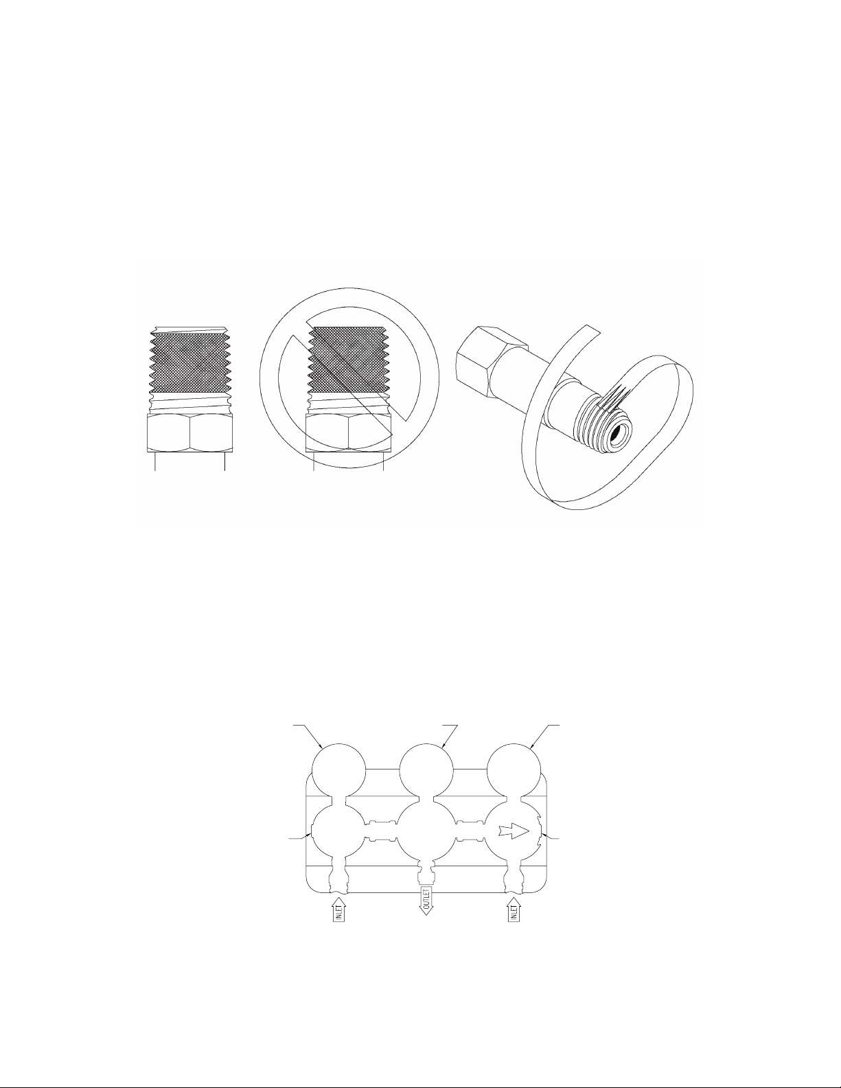
The arrow on the priority valve always points to the primary side; the bank opposite the primary side is
considered the reserve side. Starting with the arrow pointing to the right side, gas will ow from the right side
cylinder. As the gas in the primary side is depleted, the gas pressure will drop on the gauge of the primary
regulator. When the pressure drops to the pressure setting of the reserve side regulator, ow will begin from
the reserve cylinder; the inlet pressure on the primary side will stablize. This is called a changeover. At this
point, the gas pressure on the reserve side (preset regulator) will drop. This indicates that its time to change
the cylinders on the primary side. Before removing the nearly depleted primary cylinder, the priority valve
should be rotated 180°. This makes the reserve cylinder the primary source. Remove the depleted cylinder
and replace with a full cylinder. Before removing the cylinder be sure to close the cylinder valve and any
other valves that connect the cylinder to the system. Do not open any cylinder valves until all cylinders are
replaced. The full, replacement cylinder is now the reserve cylinder. Note: while changing cylinders on one
side, there will be no interruption in ow. A depleted cylinder will have the following gas pressure remaining:
Model Number
547 1XXX
547 1XXX*
547 EXXX
547 2XXX
547 3XXX
547 4XXX
Cylinder Pressure
250-350 PSIG 17-24 BAR
1050-1150 PSIG* 72-79 BAR*
1250-1500 PSIG 86-103 BAR
1800-2300 PSIG 124-159 BAR
2800-3300 PSIG 193-228 BAR
3800-4300 PSIG 262-297 BAR
*higher switch select setting for 5471XXX models
Gas will continue to ow from the primary side until the outlet pressure of the primary regulator matches the
pressure setting of the reserve regulator. (The pressure setting of the priority valve regulator changes when
the knob is turned 180°). When the gas pressure stops dropping on the primary side regulator and starts
to drop on the reserve side regulator, it is time to change the primary cylinder. The knob is rotated 180° to
the reserve side changing priority before the depleted cylinder is changed. It is helpful to maintain a log of
cylinder pressure, noting which direction the arrow is pointing on the priority valve. When the pressure gauge
is very low and the reserve side indicates that gas has begun to ow from the reserve cylinder, it is time to
rotate the knob and attach a full cylinder in reserve.
If the knob is not rotated before the empty cylinder is changed, two things can happen. First, gas may ow
from the changed cylinder to the existing cylinder. This is because the pressure setting of the regulator on
the primary side allows the regulator main valve to remain open. Second, when the cylinder is changed,
gas will begin to ow from the new cylinder, stopping ow from the existing cylinder. This means the existing
cylinder may be partially empty. After several cycles, it is possible that the reserve cylinder may empty
shortly after a switchover occurs. Always remember to rotate the knob on the priority valve regulator before
changing a depleted cylinder.
To change 5471XXX models with switch select to higher switching pressure settings to achieve maximum
outlet pressures of 800 psig. Locate the set screw that limits the travel of the right side selector knob, it is
located on the side of the knob and is screwed into a slot in the knob. When set for the lower factory default
switching pressure it is located closer to regulator body in that slot. Remove the set screw and rotate the
right side selector knob clockwise two full rotations. Reinstall the set screw. With the arrow pointing to the

9
left note the pressure reading on the right side gauge that is installed in the test port see gure 4, it should
be approx. 1050 psig then rotate the arrow clockwise to the right and note the pressure reading on the right
side gauge again it should read 1250 psig approx. Note what those two pressures are and determine the
mean between those two pressures it should be approx. 1150 psig. On the left preset regulator there is a
nut and lock washer xing the adjusting screw. Remove the nut and lock washer, rotate the adjusting screw
in clockwise to increase the setting of the left side regulator to be equal to the mean of the right side two
pressure settings (approximately 1150 psig) it should require approximately between 1 to 2 turns to set that
pressure as indicated on the left side gauge installed in the test port located on the left side regulator.
Reinstall the lock washer and nut to x the left side pressure setting. Cycle the unit thru simulated switchovers
by closing the inlet isolation valves while owing gas downstream to ensure the set pressures are xed
properly. Note that the pressures will drop slightly (approx. 30 psig) from static to owing condition this is
normal. If left side pressure needs to be reset do so ensuring it falls in the approximate middle or mean of the
two right side switching pressures.
MAINTENANCE
On regular intervals, the system should be checked for leaks and proper function (see trouble shooting).
Any leaks in the system should be corrected immediately. The pigtail check valve should also be checked
for leaks when a depleted cylinder is removed. NOTE: the system inlet and pigtail should be pressurized
when check- ing for leaks. At no time should the preset regulator’s or priority valve regulator’s pressure
settings be changed.
Typical symptoms listed below indicate regulator malfunctions needing repair. Replace immediately with a
clean, repaired and tested, or new system.
1. Gas leakage at the line regulator outlet when the adjusting screw of the line regulator is completely
backed out.
2. With no ow through the system (downstream valves closed and adjusting screw in) line pressure
steadily increases above set pressure.
3. Gas leakage from spring case (adjusting screw/knob end of regulator).
4. Gas leakage from any joint.
5. Excessive drop in working pressure with regulator owing gas.
6. Gas leakage from gauge
7. Gauge does not return to zero when not under gas pressure
8. Gauge does not consistently repeat the same reading.
10. The system makes a noise or hums.
both inlet gauges at the same time), please contact a CONCOA customer service personnel. Please be
prepared to give the following:
Model number
Gas service
Inlet pressure and type of gas supply
Outlet pressure
Approximate gas usage
NOTE: Maximum rated ow for these systems is 4000 SCFH.
TROUBLE SHOOTING

10
SERVICE
A unit that is not functioning properly should not be used. It is recommended that all servicing be done by
a service facility authorized by CONCOA. Contact CONCOA Customer Service in Virginia Beach, Virginia
for systems still covered by the warranty. For items not covered by the warranty, contact the nearest
CONCOA District Sales Ofce for assistance.
If so advised, the unit should be sent to a service facility authorized by CONCOA. Do the following before
shipping:
1. Adequately package the system. If possible package in the original shipping container.
2. Ship prepaid.
3. Include a statement of the observed deciency.
4. Indicate the gas service that the equipment was used on.
5. Purge all equipment before shipment to protect the transporter and service personnel. The purging is
especially important if the equipment has been in hazardous or corrosive gas service.
Return trip transportation charges are to be paid by the Buyer. In all cases where the warranty has expired,
repairs will be made at current list price for the replacement part(s), plus a reasonable labor charge.

11
Warranty Information
This equipment is sold by CONTROLS CORPORATION OF AMERICA under the warranties set forth in the
following paragraphs. Such warranties are extended only with respect to the purchase of this equipment directly
from CONTROLS CORPORATION OF AMERICA or its Authorized Distributors as new merchandise and are
extended to the rst Buyer thereof other than for the purpose of resale.
For a period of one (1) year from the date of original delivery (90 days in corrosive service) to Buyer or to
Buyer’s order, this equipment is warrantied to be free from functional defects in materials and workmanship and
to conform to the description of this equipment contained in this manual and any accompanying labels and/or
inserts, provided that the same is properly operated under conditions of normal use and that regular periodic
maintenance and service is performed or replacements made in accordance with the instructions provided.
The foregoing warranties shall not apply if the equipment has been repaired: other than by CONTROLS
CORPORATION OF AMERICA or a designated service facility in accordance with written instructions provided by
CONTROLS CORPORATION OF AMERICA; or altered by anyone other than CONTROLS CORPORATION OF
AMERICA; or if the equipment has been operated under improper conditions or outside published specications;
or if the equipment has been damaged or does not function due to improper installation, improper supply of
required utilities, accident, abuse, misuse, natural disaster, insufcient or excessive electrical supply, abnormal
mechanical or environmental conditions, or debris or particles in the gas or liquid source of supply.
CONTROLS CORPORATION OF AMERICA’s sole and exclusive obligation and Buyer’s sole and exclusive
remedy under the above warranties is limited to repairing using new or reconditioned parts or replacing, free
of charge except for labor if permanently installed for the continuous supply of gas by other than a technician
certied by CONTROLS CORPORATION OF AMERICA specically to do so, at CONTROLS CORPORATION
OF AMERICA’s option, the equipment or part, which is either (1) reported to its Authorized Distributor from
whom purchased, and which if so advised, is returned with a statement of the observed deciency, and proof of
purchase of equipment or part not later than seven (7) days after the expiration date of the applicable warranty,
to the nearest designated service facility during normal business hours, transportation charges prepaid, and
which upon examination, is found not to comply with the above warranties with return trip transportation charges
for the equipment or part paid by Buyer or (2) in the case of designated equipment permanently installed for
the continuous supply of gas, reported to an Authorized Service Center with proof of initial installation no later
than seven (7) days after the expiration date of the applicable warranty, and which is evaluated for compliance
with the above warranties by technician certied by CONTROLS CORPORATION OF AMERICA, and which is
determined by CONTROLS CORPORATION OF AMERICA based on said evaluation to be non-compliant.
CONTROLS CORPORATION OF AMERICA SHALL NOT BE OTHERWISE LIABLE FOR ANY DAMAGES
INCLUDING BUT NOT LIMITED TO: INCIDENTAL DAMAGES, CONSEQUENTIAL DAMAGES, OR SPECIAL
DAMAGES, WHETHER SUCH DAMAGES RESULT FROM NEGLIGENCE, BREACH OF WARRANTY OR
OTHERWISE.
THERE ARE NO EXPRESS OR IMPLIED WARRANTIES WHICH EXTEND BEYOND THE WARRANTIES
HEREINABOVE SET FORTH. CONTROLS CORPORATION OF AMERICA MAKES NO WARRANTY OF
MERCHANTABILITY OR FITNESS FOR A PARTICULAR PURPOSE WITH RESPECT TO THE EQUIPMENT
OR PARTS THEREOF.

12
Controls Corporation of America
1501 Harpers Road Virginia Beach, VA 23454
To Order Call 1-800-225-0473 or 757-422-8330 • Fax 757-422-3125
www.concoa.com
ADI 5470-B
Certified ISO 9001
®
Table of contents
Other Concoa Industrial Equipment manuals
Popular Industrial Equipment manuals by other brands

Virutex
Virutex CO49K operating instructions

Siemens
Siemens Simatic ET200pro operating instructions

Mechanical Advantage
Mechanical Advantage Sambo SB-SR Series User instructions

Vertysystem
Vertysystem Apolix Instructions for use

TE Connectivity
TE Connectivity HVA280 RA manual

Siemens
Siemens SICAM A8000 Series quick start guide