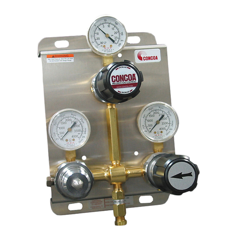
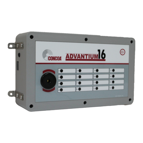
Concoa 522 Series User manual

Autoswitch Monitoring System
INSTALLATION AND OPERATION INSTRUCTIONS
Before Installing or Operating, Read and Comply with These Instructions
Controls Corporation of America
1501 Harpers Road • Virginia Beach, VA 23454
To Order Call 1-800-225-0473 or 757-422-8330 • Fax 757-422-3125
www.concoa.com
August 2000
Supersedes July 1999
Certified ISO 9000
Consists of :
522/523/536/537 Series Auto Switch
529 5298 or 529 5300 Remote Alarm
May Also Include:
529 5305 Secondary Remote Alarm
529 5306 Dialers
ADI 3170-B
®


3
529 5298 Remote alarm 120 VAC version
529 5300 Remote alarm 220 VAC version
529 5305 Secondary remote alarm
529 5306 Telephone dialer
830 9004-6 Connector assembly
Autoswitch
PART NUMBERS
USER RESPONSIBILITY
Thisequipmentwillperforminconformitywiththedescriptioncontainedinthismanualandaccompanyinglabels
and/or inserts when installed, operated, maintained, and repaired in accordance with the instructions provided.
This equipment must be checked periodically. Improperly working equipment should not be used. Parts that are
broken, missing, worn, or distorted should be replaced immediately. CONCOA recommends that a telephone or
written request for service advice be made to CONCOA Customer Service in Virginia Beach, Virginia, PHONE:
Thisequipmentoranyofits partsshould notbealtered withouttheprior written approvalbyCONCOA. Theuser
of this equipment shall have the sole responsibility for any malfunction that results from improper use, faulty
maintenance, damage, improper repair, or alteration by anyone other than CONCOA or a service facility desig-
nated by CONCOA.

4
Theautoswitch monitoringsystem isusedwhenstatusmonitoring ofthe inletpressureis needed. Thesystemcanbe
configured with multiple remote alarms. This is particularly helpful because it provides status notification to mul-
tipleusers. Thesystemmayalsobeconfigured with telephone dialers that will call the userandalert them to the low
status of up t o four autoswitches.
Connections to most of the system components are made to terminal blocks. A small flat-blade screwdriver is
required to tighten the terminal block connections on the remote alarm. Connections to the autoswitch are made
using a connector supplied by CONCOA. A soldering iron and solder are required to wire this connector. The
customersuppliesallcabling that connects the system components. Formoreinformation on installation, please see
the section that applies to the particular unit.
When using your autoswitch monitoring system, basic safety precautions must be followed to reduce the risk of fire,
electrical shock, and injury.
a. Read and understand all instructions. Follow all warnings and instructions marked on the product.
b. Install the remote alarms, dialers, or secondary remote alarms where they will not be subjected to rain or
condensation. Discontinue use of these device if it is suspected that liquids have penetrated the case; have
the device serviced.
c. Install the remote alarm and secondary remote alarm in locations where the temperature varies between 0°
and 140°F. The autoswitch may be installed in locations where the temperature varies between –40° and
140°F (-40 to 60°C).
d. Do not install the remote alarm, secondary remote alarm, or dialer in hazardous locations.
e. The nameplate on the side of the autoswitch gives instructions on installing the autoswitch in a hazardous
location.
f. Handle theremotealarm,dialer,or secondary remotealarm with care. Ifdamaged ordropped,suspenduse
immediately.
g. Operate the 529 5298 and 529 5300 remote alarm with the type of power source indicated on the remote
alarm. If you are not sure of your power source, contact your dealer or local power company.
h. Avoidoverloadingwalloutletsandextensions cords;thismayresultinelectrical shockorfire. The120VAC
remote alarm input is rated to 0.4 Amps; the 220 VAC remote alarm input is rated to 0.4 Amps.
i. Never push objects of any kind inside the case as the objects may touch dangerous voltage points or may
short parts that could result in the risk of electrical shock or fire.
j. Protect the power cord or any other connecting cables, and do not use if any wires are frayed, damaged, or
loose.
Autoswitch
The autoswitch provides visual alarm status only. The left/right banks both have alarm LED’s. The LED’s will
illuminate when the right/left bank pressure is below the alarm set point on the switchover inlet gauge. The LED’s
will turn off when the left/right bank pressure is above the alarm set point. The autoswitch power LED will be lit
when the remote alarm is connected, and the remote alarm switch is on. If the power LED is not on, the electronics
are not functioning.
Slide the red tab seen on the autoswitch inlet gauge to adjust the alarm set point. Note that CONCOA does not
recommend lowering the factory set point of the alarm system. When adjustments are made, check the function of
the system. Pressurize the system and shut off the inlet pressure to both sides. Allow the inlet pressure on the right
DESCRIPTION OF PRODUCT
GENERAL SAFETY PRACTICES
INTENDED USE OF PRODUCT

5
sideto decreaseby allowinga smallflow(50CFH/24LPM). Observebothinlet gauges. Whentheright bank islow
(below the set point on the gauge), the red LED will illuminate. Make sure the LED illuminates before the pressure
on the opposite side starts to decrease. Check the opposite side of the system in the same manner.
Adjusting the alarm set point, does not affect the switchover point of the autoswitch. The alarm is used to provide
a visual warning that a changeover is about to occur. If the nearly depleted cylinders are changed when the alarm
LED’s illuminate, the cylinders will not be as empty as if the actual changeover had occurred.
529 5298 or 529 5300 remote alarm
The 529 5298 and 529 5300 remote alarm is the centerpiece of the autoswitch monitoring system. The remote
alarm is configured at the factory for 120 VAC or 240 VAC power. The remote alarm can supply power for up to
four autoswitch systems and three secondary remote alarms. The remote alarm unit may communicate the alarm
on/alarm off status to a computer via a RS232 connection. The remote alarm may be connected to 539 5306
telephone dialer that will play customer programmed messages to customer programmed telephone numbers.
Electrical Connection
Behind Drain
Inlet Gauge: RedTab
Indicates Alarm
Setpoint (Typical Both
Sides)
Figure 2. Autoswitch Box

6
The 529 5298 and 529 5300 remote alarms provide both a visual and audible alarm. The visual alarm is indicated
by LED’s, and the audible alarm is indicated by a piezo speaker.The right/left bank LED illuminates when the bank
pressure is below the set point pressure on the switchover inlet gauge. The LED will remain lit until the bank
pressure is increased above the set point pressure. The piezo alarm will sound when the first alarm set point is
reached. However,thepiezoalarmwillnotsoundif anyotherLEDalarmsignalislit atthattime. Theaudiblealarm
will reset when all alarm LED’s are off. Silence the audio alarm by pressing the “ALARM SILENCE” button on the
remote unit.
A RS 232 connection allows the user to connect the remote alarm to a computer. The communication protocol for
the RS232 device is 1200 BPS, even parity, eight data bits, 1 stop bit. The communication data is shown in the
appendix. This is the basic binary communication that is transmitted between the computer and the remote alarm.
The terminal assignments for the remote alarm are located in the appendix. Follow the hookup instructions in the
later sections to connect the autoswitch, dialers, personal computer, and secondary remote alarms.
529 5305 secondary remote alarm
The secondary remote alarm repeats the alarm status seen on the 529 5298 or 529 5300 remote alarm. It is similar
to the remote alarm in function with respect to the LED’s and piezo alarm. It does not have the capability of adding
accessories such as a dialer or PC communication.
System 1
System 2
System 3
System 4
Terminal Blocks
Figure 1. The 529 5298/529 5300 Remote Alarm
On/Off Switch
Power LED
Power Cord
Alarm Silence
Button
PIEZO Speaker

7
529 5306 dialer
The dialer alerts the user of the low status of any of the four switchovers attached to the remote alarm. The user is
able to program the dialer’s four messages and up to eight telephone numbers. The dialer is capable of calling
numeric pagers. For more on the features of the dialer, please see the instruction booklet that comes with the dialer.
Hookup Instructions for the autoswitch monitoring system:
Follow the guidelines below when connecting the autoswitches, PC computer, dialer, and secondary remote alarms
to the 529 5298 or 529 5300 remote alarm.
Figure 4. Schematic for autoswitch installation
Terminal Blocks
Power LED
Alarm Silence Button
Figure 3. Front view of the 529 5305 Secondary Remote Alarm

8
POWER CORD
Check the input voltage configuration of the remote alarm by looking at the nameplate on the side of the remote
alarm enclosure. Do not connect the remote alarm to voltages higher or lower than those listed on the nameplate.
Units configured for 110VAC , having a 3-prong plug, should be connected to a grounded receptical. The 220/240
VAC remote alarms have three stripped wires instead of a plug. Check the nameplate to confirm that remote alarm
is intended for 220/240 VAC operation. When connecting to 220/240 VAC, use the following wire configurations:
green wire = ground
black wire = power
white wire = power
Once the power cord is connected to the power source, move the power switch to the up position. The red power
LED should illuminate.
CONNECTING THE AUTOSWITCH TO THE 529 5298
AND 529 5300 REMOTE ALARM
The following components are required to hookup the remote alarm to the autoswitch:
529 5298 or 529 5300 remote alarm
529 54XX or 529 55XX switchover system
830 9004-6 connector as shown below
soldering iron (customer supplied)
solder (customer supplied)
small flat-tip screwdriver (customer supplied)
cable (customer supplied) Note: 22 gauge wire is recommended. Cable should contain four wires. To make a water
resistant connection to the autoswitch, a round cable with outside diameter .195” - .265” must be used.
The terminal view of the 529 5298 & 529 5300 remote alarm will look like the diagram shown below. The connec-
tions to the autoswitch will use the labeled terminal blocks shown in the diagram.
INSTALLATION
Figure 5. 529 5298 and 529 5300 remote alarm terminals

9
Follow the steps below:
1. Move the power switch to the off position (down) on the 529 5298 or 529 5300 remote alarm. Disconnect
the power source to the 529 5298 or 529 5300 remote alarm.
2. Locate the connector assembly. Slide all of the cable components onto the cable as shown below.
3. Solder the four wires of one end of the cable to the pins of the plug. Please note the wire colors associated
to PIN 1, PIN 2, PIN 3, and PIN 4 (see below for pin layout).
4. Push the locking nut onto the plug.
5. Push the cable retainer into the plug until it snaps in.
6. Clamp the cable retainer tabs with pliers until the tabs lock in place on the outside cable insulation.
7. Stretch the cable cover over the cable retainer and plug. For the connector to be water resistant, the cable
cover must cover the holes on the plug.
8. Plug the cable into the male connector located on the bottom of the switchover system.
9. On the other end of the cable, strip each end of the four wires about 1/8” and insert the wire into the
appropriateterminal. Followthe wiring assignments shownin the tablebelowto wire the autoswitch to the
remote alarm.Tighten the remote alarm terminal block screw using a small, flat-tip screwdriver.
TB1-19 TB1-20 TB2-1 TB2-2 TB2-3 TB2-4 TB2-5 TB2-6 TB2-7 TB2-8 TB2-9 TB2-10
SYS 1 PIN 1 PIN 2 PIN 3 PIN 4
SYS 2 PIN 1 PIN 2 PIN 3 PIN 4
SYS 3 PIN 3 PIN 4 PIN 1 PIN 2
SYS 4 PIN 3 PIN 4 PIN 1 PIN 2
Locking
Nut
Cable
Retainer
Cable
Cover
Triangle Indicates Pin 1
Plug
Cable Retainer Tabs
Figure 6. Pin Connections
Plug

10
Recommended Installation
TB1-19 +24VDC Red wire
TB1-20 GRND Black wire
TB1-9 +24VDC Red wire
TB1-10 GRND Black wire
10. Connect the power source; turn on the remote alarm’s power switch (switch up). The power LED’s on the
autoswitch and the remote alarm should illuminate.
11. Checkthe functionofthe switchoversystembypressurizingbothsidesand allowingonesideto depressurize
at a time. When the right bank is low (below the alarm set point on the gauge), the right LED will illumi-
nate on the remote alarm and the autoswitch. The buzzer will sound if no other alarm LED’s are on. The
buzzer may be silenced on the remote alarm by pressing the remote alarm’s silence button. Check the left
side of the system in the same manner.
CONNECTING THE 529 5305 SECONDARY REMOTE ALARMS
TO THE 529 5298 REMOTE AND 529 5300 REMOTE ALARM
The following components are required to install the secondary remote alarm:
one 529 5298 or 529 5300 remote alarm connected to at least one autoswitch
secondary remote alarm (529 5305)
small flat-tip screwdriver (customer supplied)
cable (customer supplied) 22 gauge wire recommended
The terminal view of the 529 5298 & 529 5300 remote alarm will look like the diagram shown in Figure 7. The
connections to the remote alarm will use the labeled terminal blocks shown in the diagram showen in Figure 7. The
terminals will be shared with those that connect to the autoswitch.
The terminal view of the 529 5305 secondary remote alarm will look like the diagram shown in Figure 8.
Figure 7. 529 5298 and 529 5300 remote alarm terminals

11
When making connections between the remote alarms, move the power switch to the off position (down) on the
529 5298 or 529 5300 remote alarm and disconnect the power. Wire the connections as shown in Figure 9; some
connections will be unnecessary if any of autoswitches 1-4 are not present. Strip the end of each wire about 1/8”
and insert the wire into the appropriate terminal. Tighten the terminal block screw using a small flat-tip screw-
driver.
Connect the power source and turn on the power to the 529 5298 or 529 5300 remote alarm. The power LED’s on
the autoswitch, the secondary remote alarm, and the remote alarm should illuminate. Check the function of the
system by pressurizing all banks and allowing one side to depressurize at a time. When a bank is low (below the
alarm set point on the gauge), the LED will illuminate on the remote alarm, the secondary remote alarm, and the
autoswitch. The buzzer on all of the alarms will sound if no other alarm LED’s are on. Silence the buzzer by
pressing the remote alarm’s silence button.
All subsequent 529 5305 remote alarms (up to 2 more) should be connected in series off of the first 529 5305
secondary remote alarm. Match terminal to terminal.
Figure 9. Connections between two remote alarms
Figure 8. 529 5305 Secondary Remote Alarm

12
CONNECTING A PERSONAL COMPUTER’S RS 232 CONNECTION
(SERIAL PORT) TO THE 529 5298 AND 529 5300 REMOTE ALARM
The following components are required to connect the secondary remote alarm to a personal computer.
one 529 5298 or 529 5300 remote alarm connected to at least one autoswitch
small flat-tip screwdriver (customer supplied)
cable (customer supplied)
9 pin or 25 pin “D” connector (customer supplied)
personal computer with a serial port (customer supplied)
The terminal view of the 529 5298 & 529 5300 remote alarm will look like the diagram shown in Figure 11. The
connections to the remote alarm will use the labeled terminal blocks shown in the diagram.
Move the power switch to the off position and disconnect the power source on the 529 5298 or 529 5300 remote
alarm before making any connections. Connect the cable to the “D” connector before attaching the cable to the
remotealarm. Oncethe “D”connectorisattached to the cable, striptheendof each wire(atthe opposite end of the
cable) about 1/8”. Using the table below, insert the wire into the appropriate terminal. Tighten the terminal block
screw using a small flat-tip screwdriver. With the computer power off, connect the “D” connector to the computer.
Oncetheconnectionsare made, connect the powersource and movethe powerswitchto the on position on the 529
5298 or 529 5300 remote alarm. The power LED’s on the autoswitch and the remote alarm will illuminate. Turn
on the computer power.
Figure 10. Remote installation and match table.

13
CONNECTING THE 529 5306 TELEPHONE DIALER
TO THE 529 5298 AND 529 5300 REMOTE ALARM
The following components are required to install the telephone dialer.
one 529 5298 or 529 5300 remote alarm connected to at least one autoswitch
one 529 5306 telephone dialer
small flat-tip screwdriver (customer supplied)
cable (customer supplied)
Figure 12. Connector table for computer system connections.
Figure 11. 529 5298 and 529 5300 remote alarm terminals.

14
The terminal view of the 529 5298 & 529 5300 remote alarm will look like the diagram shown in Figure 13. The
connections to the remote alarm will use the labeled terminal blocks shown in the diagram.
*When connected only to TB4-1, any autoswitch system can activate the dialer. This hookup is convenient when
the dialer messages and telephone numbers are identical for systems 1-4.
With the power source disconnected and the power switch in the off position (down) on the 529 5298 or 529 5300
remote alarm, wire the dialer to the remote alarm as outlined in the table below. All “C”’ terminals on the dialer
must be tied together.
Connect the power source and turn on the power to the 529 5298 or 529 5300 remote alarm. The power LED’s on
the autoswitch and the remote alarm will illuminate. Follow the directions supplied with the dialer to setup the
dialer.
Figure 14. Dialer to terminal table.
Figure 13. 529 5298 and 529 5300 remote alarm terminals

15
1. PROBLEM: With the power switch on (up), the power LED on the 529 5298 or 529 5300 remote alarm
is not illuminated:
SOLUTION:
A. Check the power cord connections to make sure the unit is plugged in correctly.
B. Check to see if the wall outlet is receiving power.
C. Finally, check the fuses in the remote alarm to see if they have blown by following these steps.
Before removing the remote alarm’s rear cover, disconnect the power cord from the power source.
Even though the power switch may be off, there are still live circuits on the board. Touching these
circuits will cause electrical shock. Move the power switch to the off position (down). Remove the
screws indicated below and remove the rear cover. Two fuses will be located on the back of the
circuit board. Replace the fuses with the equivalent indicated on the fuse label (located next to the
fuses). Replace the rear cover and screws; reconnect the power cord to the power source. Move the
power switch to the on position. Observe the power LED. If the power LED flashes briefly and
remains off, one of the components connected to the remote alarm is attached incorrectly. Correct
the improperly wired connections and replace the fuses again.
2. PROBLEM: The 529 5298 or 529 5300 remote alarm power LED is on; however, all of the autoswitch
power LED’s and secondary remote alarm LED’s are not lit:
SOLUTION:
Move the power switch to the off position (down). Check the connections to the different components.
Once all the connections are wired correctly, move the power switch to the on position. If the problem was
notcorrected,oneof the fuses intheremotealarm may be blown. Using the instructions in step 1-C,check
fuse2inthe529 5298or5295300remotealarm. Replacethefuseifnecessarywiththeequivalentlistedon
the label near the fuses.
Figure 15. Fuse access on the 529 5298/529 5300.
TROUBLESHOOTING

16
3 PROBLEM: At least one autoswitch or secondary remote alarm component is working; however, one or
more other autoswitches or secondary remote alarm components are not working:
SOLUTION:
With the power switch “off” on the 529 5298 or 529 5305 remote alarm, check the wiring to the malfunc-
tioning components. Correct the wiring.
4. PROBLEM: The 529 5298 or 529 5300 remote alarm power LED and the autoswitch power LED is on;
however, the 529 5305 secondary remote alarm power LED is not lit:
SOLUTION:
Move the power switch on the 529 5298 or 529 5305 remote alarm to the off position (down), and discon-
nect the power source and . Correct any improperly wired connections from the remote alarm to the
secondary remote alarm. Turn on the power switch. If the secondary remote alarm LED does not illumi-
nate, check the secondary remote alarm fuse by following these steps. Move the power switch on the 529
5298or5295300remote alarmtotheoffposition(down). Removethefourscrewsandrearpanel. Replace
the fuse with the equivalent fuse shown on the label. Replace the rear cover and four screws. Turn on the
power to the 529 5298 or 529 5300 remote alarm; check the malfunctioning unit.
A unit that is not functioning properly should not be used. It is recommended that all servicing be done by a service
facility authorized by CONCOA. Contact CONCOA Customer Service in Virginia Beach, Virginia for systems
still covered by the warranty. For items not covered by the warranty, contact the nearest CONCOA District Sales
Office for assistance.
If so advised, the unit should be sent to a service facility authorized by CONCOA. Do the following before ship-
ping:
1. Adequately package the system. If possible package in the original shipping container.
2. Ship prepaid.
3. Include a statement of the observed deficiency.
Return trip transportation charges are to be paid by the Buyer. In all cases where the warranty has expired, repairs
will be made at current list price for the replacement part(s), plus a reasonable labor charge.
SERVICE

17
APPENDIX
if X = 0: alarm on if X = 1: alarm off
Thebinaryinformation abovewill typicallybe convertedto ASCIIcode bythecomputer. Itis moreuseful
to again convert the data to binary code. This will allow the user to “look at” the status of each system.
Utilizing software such as BASIC, Software Wedge, or LABVIEW, the user can poll the remote alarm for
theinformation. Theabovedatabytewillbe repeated16timeseverytimetheremotealarmis polled. The
last 15 bytes of information may be ignored.
Terminal Assignments for the 529 5298 & 529 5300 Remote Alarm
TB1-19 – power +24 VDC output
TB1-20 – ground 0 VDC
TB2-1 – system 1 left bank +24 VDC alarm on/0 VDC alarm off input
TB2-2 – system 1 right bank +24 VDC alarm on/0 VDC alarm off input
TB2-3 – system 2 left bank +24 VDC alarm on/0 VDC alarm off input
TB2-4 – system 2 right bank +24 VDC alarm on/0 VDC alarm off input
TB2-5 – system 3 left bank +24 VDC alarm on/0 VDC alarm off input
TB2-6 – system 3 right bank +24 VDC alarm on/0 VDC alarm off input
TB2-7 – system 4 left bank +24 VDC alarm on/0 VDC alarm off input
TB2-8 – system 4 right bank +24 VDC alarm on/0 VDC alarm off input
TB2-9 – power +24 VDC output
TB2-10 – ground 0 VDC
TB4-1 – system 1-4 ground (alarm on) / open circ. (alarm off)
System 4
right bank System 3
right bank System 1
right bank
XXXXXXXX
System 4
right bank System 2
right bank System 2
right bank System 1
right bank
System 3
right bank
Condition
Output
RS 232 COMMUNICATION

18
TB4-2 +10 VDC output
TB4-3 – system 1 ground (alarm on) / open circ. (alarm off)
TB4-4 +10 VDC output
TB4-5 – system 2 ground (alarm on) / open circ. (alarm off)
TB4-6 +10 VDC output
TB4-7 – system 3 ground (alarm on) / open circ. (alarm off)
TB4-8 +10 VDC output
TB4-9 – system 4 ground (alarm on) / open circ. (alarm off)
TB4-10 +10 VDC output
TB5-1 – data transmitted to PC
TB5-2 – data received by the r. alarm
TB5-3 – ground

19

Controls Corporation of America
1501 Harpers Road • Virginia Beach, VA 23454
To Order Call 1-800-225-0473 or 757-422-8330 • Fax 757-422-3125
www.concoa.com
Certified ISO 9001
ADI 3170-B
®
Other manuals for 522 Series
1
This manual suits for next models
3
Table of contents
Other Concoa Measuring Instrument manuals
Popular Measuring Instrument manuals by other brands

EZAutomation
EZAutomation EZ3-TouchPLC quick start guide

PerkinElmer
PerkinElmer Lambda 465 installation instructions

TECHNO-AC
TECHNO-AC AG-309.15G Technical Description, Operating Instructions

ABQINDUSTRIAL
ABQINDUSTRIAL Dakota Ultrasonics ZX-2 instruction manual

parktool
parktool DC-1 instructions

Zero88
Zero88 DMX DeBug manual