CONCORD COMO SL 4.0 User manual

ENGLISHFRANÇAISDEUTSCHČESKYHRVATSKIFREE SLOT SLOVENŠČINA
TABLE OF CONTENTS
1. INTRODUCTION .............................................................................................................................. 1
1.1. WARRANTY..........................................................................................................................................................................................1
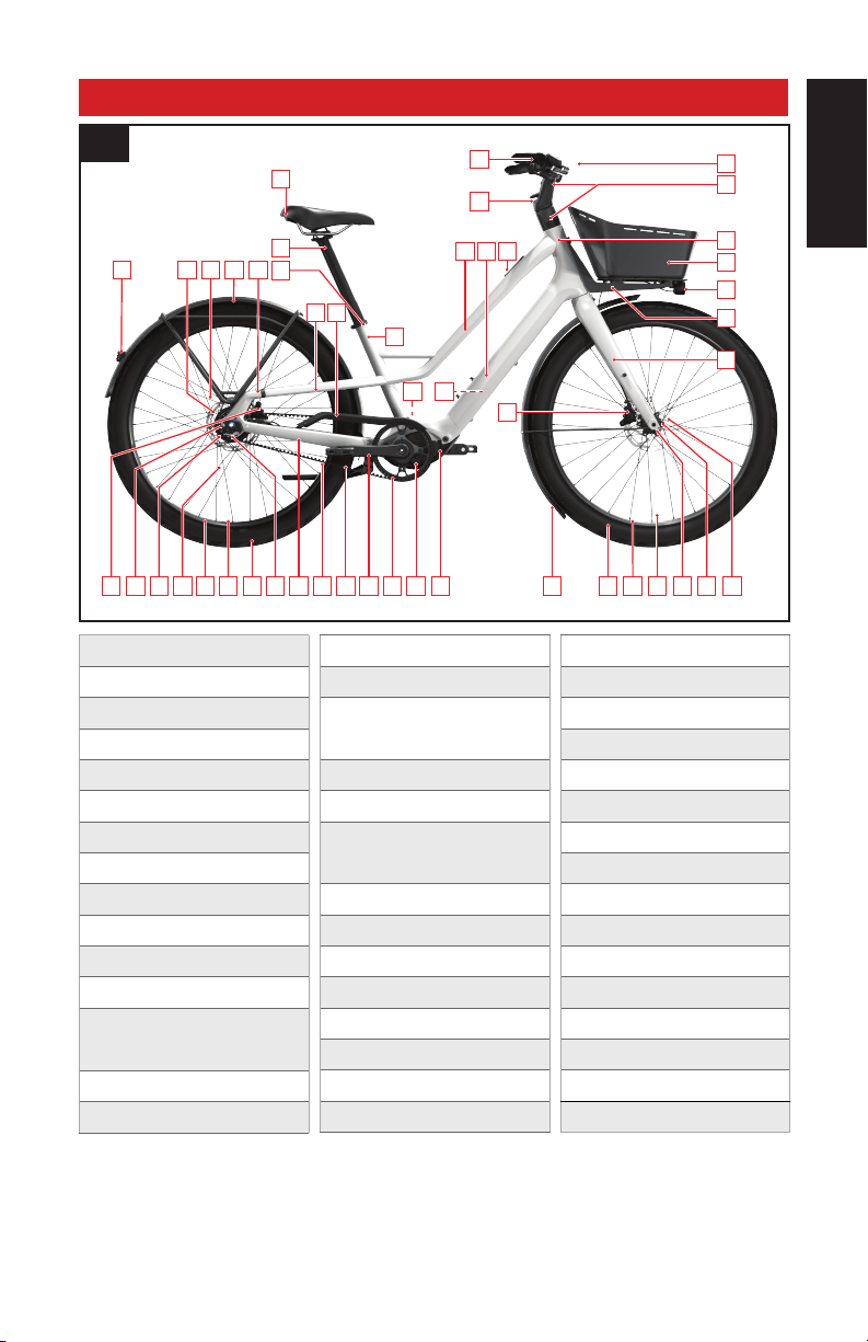
2. COMO SL COMPONENTS ............................................................................................................... 2
3. GENERAL INFORMATION ABOUT YOUR COMO SL .......................................................................... 4
3.1. INTENDED USE ..................................................................................................................................................................................4
3.2. PEDELEC / EPAC...............................................................................................................................................................................4
4. GENERAL NOTES ABOUT RIDING................................................................................................... 5
4.1. RIDING TIPS........................................................................................................................................................................................5
4.2. BEFORE RIDING................................................................................................................................................................................5
4.3. KNOW YOUR RANGE........................................................................................................................................................................6
4.4. REMOVABLE YELLOW STICKER.....................................................................................................................................................6
4.5. RIDING WITH KIDS ...........................................................................................................................................................................6
5. GENERAL NOTES ABOUT ASSEMBLY............................................................................................. 7
5.1. SEATPOST ..........................................................................................................................................................................................7
5.2. SPEED SENSOR................................................................................................................................................................................8
5.3. COCKPIT ............................................................................................................................................................................................8
6. GENERAL NOTES ABOUT MAINTENANCE....................................................................................... 10
6.1. REPLACEMENT PARTS AND ACCESSORIES .................................................................................................................................10
7. HANDLEBAR .................................................................................................................................. 11
8. LIGHTING, RACKS, BASKET AND FENDERS ................................................................................... 11
9. REAR WHEEL AND INTERNAL GEAR HUB ...................................................................................... 14
9.1. REMOVING AND REINSTALLING THE REAR WHEEL....................................................................................................................14
9.2. DRIVETRAIN TENSION / REAR WHEEL ALIGNMENT..................................................................................................................16
9.3. SEATSTAY COUPLER........................................................................................................................................................................17
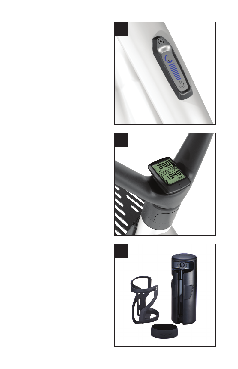
10. DISPLAY INTERFACE (TCU) .......................................................................................................... 18
10.1. TURBO CONNECT UNIT (TCU)........................................................................................................................................................18
10.2. STARTING THE SYSTEM ON THE TCU..........................................................................................................................................18
10.3. CHANGING SUPPORT MODES ON THE TCU ...............................................................................................................................19
10.4. CONNECTIVITY OPTIONS...............................................................................................................................................................19
10.5. ERROR CODES ................................................................................................................................................................................19
10.6. FACTORY RESET .............................................................................................................................................................................20
10.7. CHANGING THE INTERNAL TCU BATTERY ..................................................................................................................................21
11. MISSION CONTROL....................................................................................................................... 22
11.1. DOWNLOAD AND INSTALL MISSION CONTROL...........................................................................................................................22
11.2. PAIRING YOUR BICYCLE WITH MISSION CONTROL ...................................................................................................................22
11.3. MISSION CONTROL FUNCTIONS ...................................................................................................................................................22
12. BATTERY AND CHARGER.............................................................................................................. 24
12.1. CHARGING AND USING THE BATTERY..........................................................................................................................................24
12.2. CHARGING THE BATTERY..............................................................................................................................................................25
12.3. CHARGE LEVEL DISPLAY...............................................................................................................................................................26
12.4. CLEANING.........................................................................................................................................................................................26
12.5. STORAGE..........................................................................................................................................................................................27
12.6. TRANSPORT.....................................................................................................................................................................................27
12.7. DISPOSAL.........................................................................................................................................................................................27
12.8. BATTERY TECHNICAL DATA...........................................................................................................................................................28
12.9. CHARGER TECHNICAL DATA .........................................................................................................................................................28
13. SPECIFICATIONS.......................................................................................................................... 30
13.1. GENERAL SPECIFICATIONS............................................................................................................................................................30
13.2. BOLT SIZE / TOOLS / TORQUE SPECIFICATIONS........................................................................................................................30
13.3. RECOMMENDED TIRE PRESSURES.............................................................................................................................................31
14. RANGE EXTENDER ....................................................................................................................... 32
15. REGULATORY STATEMENTS......................................................................................................... 35
16. EC – DECLARATION OF CONFORMITY ........................................................................................... 36
We may occasionally issue updates and addendums to this document.
Please periodically check www.specialized.com or contact Rider Care to
make sure you have the latest information.
Info: specialized.com / 877-808-8154
EPAC according to EN 15194
SPECIALIZED BICYCLE COMPONENTS
15130 Concord Circle, Morgan Hill, CA 95037 (408) 779-6229
0000156717_UM_R1, 09/20

1
1. INTRODUCTION
THIS USER MANUAL CONTAINS IMPORTANT INFORMATION. PLEASE READ CAREFULLY AND STORE IN A
SAFE PLACE.
This manual was drafted in the English language (Original instructions) and may have been translated into
other languages as applicable (translation of Original instructions).
This user manual is specific to your Specialized Turbo COMO SL bicycle and should be read in addition to the
Specialized Bicycle Owner’s Manual (“Owner’s Manual”). It contains important safety, performance and technical
information, which you should read before your first ride and keep for reference. You should also read the entire
Owner’s Manual, because it has additional important general information and instructions which you should follow.
If you do not have a copy of the Owner’s Manual, you can download it at no cost at www.specialized.com, or obtain
it from your nearest Authorized Specialized Retailer or Specialized Rider Care.
Additional safety, performance and service information for specific components such as suspension or
pedals on your bicycle, or for accessories such as helmets or lights, may also be available. Make sure that your
Authorized Specialized Retailer has given you all the manufacturers’ literature that was included with your bicycle
or accessories. In case of a conflict between the information in this user manual and information provided by a
component manufacturer, please contact your nearest Authorized Specialized Retailer.
The COMO SL is classified as an EPAC (Electrically Power Assisted Cycle, otherwise known as a Pedelec), and is
referred to in this manual as a bicycle unless otherwise noted.
ADDITIONAL LANGUAGES ARE AVAILABLE FOR DOWNLOAD AT www.specialized.com.
When reading this user manual, you will note various important symbols and warnings, which are explained below:
WARNING! The combination of this symbol and word indicates a potentially hazardous situation
which, if not avoided, could result in serious injury or death. Many of the warnings say “you
may lose control and fall.” Because any fall can result in serious injury or even death, we do not
always repeat the warning of possible injury or death.
CAUTION: The combination of the safety alert symbol and the word CAUTION indicates a
potentially hazardous situation, which, if not avoided, may result in minor or moderate injury, or
is an alert against unsafe practices.
The word CAUTION used without the safety alert symbol indicates a situation which, if not
avoided, could result in serious damage to the bicycle or the voiding of your warranty.
INFO: This symbol alerts the reader to information which is particularly important.
TECH TIP: Tech Tips are useful tips and tricks regarding installation and use.
GREASE: This symbol means that high quality grease should be applied as illustrated.
CARBON FRICTION PASTE: This symbol means that carbon friction paste should be applied as
illustrated to increase friction.
TORQUE: This symbol highlights the correct torque value for a specific bolt. In order to achieve
the specified torque value, a quality torque wrench must be used.
1.1. WARRANTY
A copy of the applicable written Specialized warranty policy is provided with your bicycle, and is available from your
Authorized Specialized Retailer. It is also available for download at www.specialized.com.

ENGLISHFRANÇAISDEUTSCHČESKYHRVATSKIFREE SLOT SLOVENŠČINA
2
2. COMO SL COMPONENTS
16 1712
19
40
20
2 231
3
39
4
41
7
5
6 45
8
9
10
11334426 28 1329
27
2931 1415
1822
43363842
24
2532343035 3130
21
37
2.1
1. TOP TUBE
2. DOWN TUBE
3. SEAT TUBE
4. HEAD TUBE
5. CHAINSTAY
6. SEAT STAY
7. FORK
8. SADDLE
9. SEATPOST
10. SEATPOST CLAMP
11. BELT * / CHAIN DRIVE
12. BELT SPROCKET* / CHAINRING
13. BELT SPROCKET* / REAR
CHAINRING
14. CRANK ARM
15. PEDAL
16. MOTOR
17. MOTOR COVER
18. INTERNAL RECHARGEABLE
BATTERY
19. SHIFTER
20. BRAKE LEVER
21. INTEGRATED HANDLEBAR /
STEM
22. CHARGING SOCKET
23. TCU DISPLAY
24. FRONT BRAKE CALIPER
25. FRONT BRAKE ROTOR
26. REAR BRAKE CALIPER
27. REAR BRAKE ROTOR
28. SPOKE
29. RIM
30. TIRE
31. VALVE
32. FRONT HUB
33. INTERNAL GEAR HUB
34. THRU-AXLE
35. FRONT FENDER
36. REAR FENDER
37. FRONT RACK
38. REAR RACK
39. BASKET*
40. TCD DISPLAY*
41. FRONT LIGHT
42. REAR LIGHT
43. SEATSTAY COUPLER
44. ADJUSTABLE DROPOUT
45. CHAIN GUARD
COMO SL 5.0 *

3
TURBO CONNECT UNIT (TCU)
All Turbo COMO SL models are all equipped with the
TCU display (Fig. 2.2). The display turns on the motor,
and provides access to the support modes options,
as well as the battery state of charge and error codes.
TURBO CONNECT DISPLAY (TCD)
The Turbo Connect Display (TCD) is an optional
display (Fig. 2.3) designed specifically for use with
certain Turbo bicycle models. The TCD is optimized
to help you interface with your bicycle to access your
data, such as speed, distance, cadence, rider power,
battery level and time. The TCD is available through
your local Authorized Specialized Retailer.
RANGE EXTENDER (RE)
Your COMO SL is compatible with the RE (Fig. 2.4),
to further increase range and ride time. The RE is
securely held in the supplied Zee Cage II Right and
the Specialized battery retention band. The RE
connects to the motor through a dedicated power
cable that plugs into the charge port.
Use the RE together with the 220 mm RE Cable. The
RE and RE Cable are available through your local
Authorized Specialized Retailer.
2.3
OPTIONAL
2.2
2.4
OPTIONAL

ENGLISHFRANÇAISDEUTSCHČESKYHRVATSKIFREE SLOT SLOVENŠČINA
4
3. GENERAL INFORMATION ABOUT YOUR COMO SL
3.1. INTENDED USE
The COMO SL is intended, tested and designed for riding on a paved surfaces, smooth gravel roads, and improved
trails with moderate grades where the tires do not lose ground contact. (Condition 2).
For more information on intended use and structural weight limits, please refer to the Specialized Owner’s Manual.
Before using your COMO SL bicycle, please inform yourself of all applicable legal requirements
and regulations in your country or state. There may be restrictions on riding your COMO SL
bicycles on public roads, cycling paths, and/or trails. There may also be applicable helmet
requirements, age restrictions or license or insurance requirements. Specialized does not, and will
not, make any promise, representation, or warranty regarding the use of your COMO SL bicycle.
As laws and regulations regarding electric bicycles vary by country and/or state and are constantly
changing, please make sure to obtain the latest information. You should also regularly see your
Authorized Specialized Retailer for updated information.
CAUTION: All COMO SL bicycles have a fixed pre-set speed limit at which the motor support
will automatically shut off. Any (attempted) tampering with the power output and/or system is
prohibited and will void the warranty.
3.2. PEDELEC / EPAC
The COMO SL is classified as an EPAC. (Electrically Power Assisted Cycle)
Your motor support will automatically switch off when you reach a maximum speed of 25 km/h (15.5 mph) or 28
mph in the US and 20 mph in Canada. A driver’s license or insurance is typically not required.
Per EN 15194: The A-weighted emission sound pressure level at the driver ears is less than 70 dB(A).

5
4. GENERAL NOTES ABOUT RIDING
The COMO SL motor provides pedal assistance only while you are pedaling and the bicycle is in motion. The
amount of pedal assistance will be higher or lower depending on the amount of force applied to the pedals. If you
stop pedaling, the motor will stop providing any assistance.
The COMO SL bicycle can also be ridden as a normal bicycle without motor assistance by switching the display to
the OFF mode. The same applies if the battery charge drops below 5% - 3%.
4.1. RIDING TIPS
Because of the electric motor assist, the COMO SL offers a unique riding experience compared to a bicycle without
motor assist. Below are some riding tips which may also reduce component wear and increase battery range:
Pay attention to your speed going into a corner and be sure to stop pedaling well before entering the corner.
Otherwise you may carry too much speed when entering a corner.
Ride efficiently and look ahead. Any time braking force is applied, more energy is needed to get the bicycle back
up to speed.
Shift gears regularly to stay in an optimal cadence range and downshift before coming to a stop.
Reduce pedal force before initiating a gear shift to reduce drivetrain wear.
Braking while steering may reduce the ability to control your bicycle.
Check the tire pressure regularly. Low pressure can cause the tires to roll inefficiently.
Do not expose your bicycle to prolonged excessive heat (e.g. direct sunlight).
Only carry the cargo you need. More weight will drain the battery faster.
If your bicycle is exposed to cooler temperatures (0 degrees), keep the bicycle stored indoors until just before
riding.
WARNING! The motor support is activated as soon as you step onto the pedals and the bicycle
is in motion. You should be seated on the bicycle and engage at least one brake before starting
to pedal. Do not put one foot on a pedal and throw a leg over the bicycle, as it could accelerate
unexpectedly. Failure to follow this warning may result in serious personal injury or even death.
WARNING! The acceleration of an electric bicycle can be faster than anticipated and may feel
unusual at first. Before your first ride, you should use the lowest power ECO mode and become
familiar with the operation of the electric bicycle by practicing starting and stopping, cornering
and navigating obstacles in a safe environment away from other bicycles, pedestrians and/or
vehicles. Due to the greater acceleration of an electric bicycle, you should also pay particular
attention to terrain conditions as you may approach obstacles faster than expected. Please note
the default motor support mode upon startup is always SPORT mode.
CAUTION: The weight of your COMO SL is significantly higher than a bicycle without motor
support. Use caution when handling the bicycle (including, but not limited to parking, lifting,
pushing, loading it into a car or onto a bicycle carrier and unloading it).
4.2. BEFORE RIDING
Regardless of your experience level, you should read the “FIRST” section of your Owner’s Manual (Bike Fit, Safety
First, Mechanical Safety Check and First Ride) and carry out all important safety checks. In addition, make sure you
are familiar with the following areas of the bicycle that are specific to electric bicycles.
BEFORE YOUR FIRST RIDE:
BATTERY: Is the battery fully charged?
TCU DISPLAY: Are you familiar with the function of the display features?
BEFORE EVERY RIDE:
BATTERY: Do you have sufficient battery charge?
TCU DISPLAY: Is the display functioning correctly?
WARNING! If your battery, charger or other component exhibits any signs of damage, do not use
the bicycle and immediately bring it to your Authorized Specialized Retailer for inspection.

ENGLISHFRANÇAISDEUTSCHČESKYHRVATSKIFREE SLOT SLOVENŠČINA
6
4.3. KNOW YOUR RANGE
Know the range of your electric bicycle before you start your ride. You can calculate your range by visiting www.
specialized.com, selecting your Turbo Bicycle model, then clicking on the range calculator. In addition to the range
calculator, we recommend using the Smart Control feature in the Mission Control App to control your range.
4.4. REMOVABLE YELLOW STICKER
Your COMO SL bicycle has a removable yellow
sticker adhered to the frame, stating the
bicycle serial number and your personal BLE
(BLUETOOTH LOW ENERGY) pairing code.
Remove this sticker from the bicycle and place it on
the last page of this manual for future reference.
4.5. RIDING WITH KIDS
There are many different setups that allow you to ride with kids. Please look at the Riding Safely section in the
Owner’s Manual regarding general information and instructions on child carriers or trailers.
If you regularly ride with kids on your bicycle, your Authorized Specialized Retailer should conduct a periodic safety
inspection.
WARNING! Specialized bicycles are only designed and tested for use by one person at a time.
Carrying a child on your Specialized bicycle is at your own risk. If you choose to install an
accessory on your Specialized bicycle such as a trailer, carrier, or trailer cycle, make sure it is
compatible and refer to the manufacturer’s instructions and your Authorized Specialized Retailer.
You should make sure your bicycle is still safe to ride with the accessory installed. Be sure to not
exceed the structural weight limit of the bicycle when using a trailer, trailer cycle or child carrier.
Also make sure not to exceed the maximum cargo weight when using a child carrier.
WARNING! Riding with kids on your bicycle will affect the handling by altering the center of gravity,
weight and balance. It may also negatively impact your cornering ability, increase your stopping
distance and reduce your ability to slow down and maneuver, especially at higher speeds or down
a steep grade. All of this can result in a loss of control, potentially causing serious injury and/or
death. You should also become familiar with and practice riding with the accessory in a controlled
environment away from traffic.
WARNING! Do not attach a child carrier, trailer or similar accessory to a composite or carbon fiber
part or component, either directly or indirectly. For example, do not attach a trailer to a rear axle
when the rear triangle is made of composite or carbon fiber. Likewise, do not attach a trailer cycle
to a composite or carbon seatpost or a child carrier to a composite or carbon fork. Either may
potentially apply unusual forces on your bicycle frame or component which could result in damage
and cause a complete failure, with the risk of serious injury or death. If you have previously
attached an accessory to a composite or carbon fiber part or component, do not ride until you
have had your Authorized Specialized Retailer conduct a careful safety inspection.
Before riding with kids on your bicycle, please inform yourself of all applicable legal requirements
and regulations in your country and state. There may be restrictions on riding your bicycle with
certain or any accessory(ies). This is especially true for electric and pedal-assist bicycles.
BLE:
599716
4.1

7
5. GENERAL NOTES ABOUT ASSEMBLY
This user manual is not intended as a comprehensive use, service, repair or maintenance guide. Please see your
Authorized Specialized Retailer for all service, repairs or maintenance. Your Authorized Specialized Retailer may
also be able to refer you to classes, clinics or books on bicycle use, service, repair, and maintenance.
WARNING! Due to the complexity of the COMO SL bicycle, proper assembly requires a high degree
of mechanical expertise, skill, training and specialty tools. Therefore, it is essential for your safety
that the assembly, maintenance and troubleshooting be performed by an Authorized Specialized
Retailer. Before your first ride, make sure your components, such as brakes and drivetrain, are
assembled and adjusted in accordance with the manufacturer’s instructions and are functioning
properly.
WARNING! Many components on the COMO SL, including, but not limited to the motor, battery
and cable guides, are proprietary to the COMO SL. Only use originally supplied components and
hardware at all times. Use of other components or hardware will compromise the integrity and
strength of the assembly. COMO SL specific components should only be used on the COMO SL
and not on other bicycles, even if they fit. Failure to follow this warning could result in serious
injury or death.
WARNING! Never modify your frame or bicycle in any way. Do not sand, drill, file or remove parts
from your bicycle. Do not install incompatible components or hardware. Failure to follow this
warning may result in serious personal injury or death.
WARNING! Electrical components can be exposed when working on your bicycle. Do not touch
any part of the electrical system while under electric charge. Do not expose the connections of
the battery and frame to water. If any live components or the battery are damaged, stop riding
immediately and bring your bicycle to your Authorized Specialized Retailer.
5.1. SEATPOST
SEATPOST INSTALLATION - SEAT COLLAR
Ensure the seat collar is positioned so the slot
faces backwards (Fig. 5.1).
Verify the saddle height and position, adjust if
necessary.
Torque the seat collar to 55 in-lbf / 6.2 Nm.
The fit between the seatpost and the seat tube must allow the seatpost to slide into the seat tube
smoothly and without twisting, but not so loosely that there’s excessive side-to-side play/wiggle.
Any fit and/or torque issues should be inspected by your Authorized Specialized Retailer. If the
seatpost does not fit properly or moves in the frame even though it is torqued to spec, you should
have it inspected by your Authorized Specialized Retailer.
5.1

ENGLISHFRANÇAISDEUTSCHČESKYHRVATSKIFREE SLOT SLOVENŠČINA
8
SEATPOST MINIMUM INSERTION:
To prevent damage to the frame and/or seatpost, it
is important to have a minimum amount of seatpost
insertion in the seat tube. This minimum insertion
must meet the following requirements:
The seatpost must be inserted into the frame
deep enough so the minimum insertion/maximum
extension (min/max) mark on the seatpost is not
visible (Fig. 5.2 A).
The seatpost must also be inserted into the seat
tube deep enough to meet or exceed the 115 mm
minimum measured insertion depth (Fig. 5.2 B)
required by the frame.
If the seatpost and frame minimum insertion
requirements differ from each other, always use the
longer minimum insertion. For example, if the frame
requires 115 mm, but the seatpost requires 90 mm,
then 115 mm is the minimum insertion required.
If the seatpost is at the min/max mark and the seatpost does not meet or exceed the minimum measured insertion
depth of the frame, the seatpost is not inserted deeply enough into the seat tube and should be lowered until it
meets or exceeds the frame insertion requirement. This may result in the saddle being too low. If so, the seatpost
must be replaced with a longer seatpost.
WARNING! Failure to follow the seatpost and frame minimum insertion requirements may result in
damage to the frame and/or seatpost, which could cause you to lose control and fall.
If the seatpost is cut short, the min/max mark on the seatpost may no longer be accurate. Before
cutting the seatpost, note the min/max depth required by the seatpost manufacturer.
WARNING! For general instructions regarding the installation of the seatpost, refer to the
appropriate section in the Owner’s Manual. Riding with an improperly tightened seatpost can
allow the saddle to turn or move and cause you to lose control and fall.
CAUTION: Inspect the seatpost and seat tube to ensure that there are no burrs or sharp edges.
Remove any burrs or sharp edges using fine grit sandpaper.
5.2. SPEED SENSOR
The COMO SL is equipped with a Speed Sensor magnet, located on the rear hub/disc rotor interface. Dirt and/or
metal debris may accumulate on the Speed Sensor magnet. Too much accumulation may result in interruptions in
motor support and/or inaccurate speed readings.
Regularly check your Speed Sensor magnet for accumulation of dirt and/or metal debris, and clean accordingly. The
frequency of the cleaning depends on your riding conditions, ride frequency and/or brake pad material. Removing
metal debris may require the use of a magnet stronger than the Speed Sensor magnet.
5.3. COCKPIT
The COMO SL has a fully internally routed cockpit. The brake, shifter, and lighting cables are routed inside the head
tube, steerer tube, and handlebar system.
WARNING! Due to the high degree of complexity of the COMO SL, proper assembly of the cockpit
requires a high degree of mechanical expertise, skill, training and specialty tools. Therefore, it is
essential that the assembly, maintenance and troubleshooting be performed by an Authorized
Specialized Retailer.
A
B
5.2

9
5.3
The steerer tube has a built-in steering limiter to prevent any damage to the internally routed cables (Fig. 5.3).
This steering limiter will affect your ability to turn sharply. Familiarize yourself with the handling of the bicycle by
practicing in an open area without any obstructions.

ENGLISHFRANÇAISDEUTSCHČESKYHRVATSKIFREE SLOT SLOVENŠČINA
10
6. GENERAL NOTES ABOUT MAINTENANCE
The COMO SL is a high performance bicycle. All regular maintenance, troubleshooting, repair and parts
replacement must be performed by an Authorized Specialized Retailer. For general information regarding
maintenance of your bicycle, please refer to the Owner’s Manual. In addition, routinely perform a Mechanical Safety
Check before each ride, as described in the Owner’s Manual.
Great care should be taken to not damage carbon fiber or composite material. Any damage may result in a loss
of structural integrity, which may result in a catastrophic failure. This damage may or may not be visible during
inspection. Before each ride, and after any crash, you should carefully inspect your bicycle for any fraying,
gouging, scratches through the paint, chipping, bending, or any other signs of damage. Do not ride if your bicycle
shows any of these signs. After any crash, and before you ride any further, take your bicycle to an Authorized
Specialized Retailer for a complete inspection.
While riding, listen for any creaks, as a creak can be a sign of a problem with one or more components.
Periodically examine all surfaces in bright sunlight to check for any small hairline cracks or fatigue at stress
points, such as welds, seams, holes, and points of contact with other parts. If you hear any creaks, see signs of
excessive wear, discover any cracks, no matter how small, or any damage to the bicycle, immediately stop riding
the bicycle and have it inspected by your Authorized Specialized Retailer.
Lifespan and the type and frequency of maintenance depends on many factors, such as use, rider weight,
riding conditions and/or impacts. Additionally, the COMO SL uses a power-assisted drive system, which means
more distance is covered in the same amount of time. Components may be subject to increased wear at
different rates, depending on the component. Drivetrain and brake components are especially subject to wear.
Periodically have your Authorized Specialized Retailer inspect your bicycle and components for wear.
Exposure to harsh elements, especially salty air (such as riding near the ocean or in the winter), can result in
galvanic corrosion of components such as the crank spindle and bolts, which can accelerate wear and shorten
the lifespan. Dirt can also accelerate wear of surfaces and bearings. The surfaces of the bicycle should be
cleaned before each ride. The bicycle should also be maintained regularly by an Authorized Specialized Retailer,
which means it should be cleaned, inspected for signs of corrosion and/or cracks and lubricated. If you notice
any signs of corrosion or cracking on the frame or any component, the affected item must be replaced.
Regularly clean and lubricate the drivetrain according to the drivetrain manufacturer’s instructions.
Do not use a high pressure water spray directly on the bearings. Even water from a garden hose can penetrate
bearing seals and crank interfaces, increasing bearing and crank wear. Use a clean, damp cloth and bicycle
cleaning agents for cleaning.
Do not expose the bicycle to prolonged direct sunlight or excessive heat, such as inside a car parked in the sun
or near a heat source such as a radiator.
From time to time, clean the Speed Sensor magnet on the rear wheel with a soft cloth. Depending on your ride
conditions and brake pad choice, dirt and/or metal shavings can collect on the Speed Sensor magnet, which could lead
to interruptions in motor support or wrong speed readings.
WARNING! Failure to follow the instructions in this section may result in damage to the
components on your bicycle and will void your warranty, but, most importantly, may result in
serious personal injury or death. If your bicycle exhibits any signs of damage, do not use it and
immediately bring it to your Authorized Specialized Retailer for inspection.
WARNING! Use a repair stand to support the bicycle during assembly or maintenance, and a
bicycle rack for transportation.
When placing the frame and/or bicycle in a repair stand, clamp the stand to the seatpost and not
the frame. Clamping the frame can cause damage to the frame that may or may not be visible, and
you may lose control and fall.
WARNING! Always turn off the battery when not in use and/or when working on the bicycle.
CAUTION: Do not open the motor assembly. The motor assembly is a sealed maintenance-free
system. Any work on the motor assembly must be performed by a Specialized Service Center.
6.1. REPLACEMENT PARTS AND ACCESSORIES
Specialized replacement parts and accessories are available through your Authorized Specialized Retailer.

11
7. HANDLEBAR
The COMO SL is equipped with a custom designed handlebar assembly which is setup differently to other
handlebars.
7.1
5
5
i
n
-
l
b
f
6
.
2
N
m
T25
The handlebar alignment can be adjusted by loosening the bolts located behind a cover on the integrated
handlebar stem (Fig. 7.1). Make sure there are equal gaps on the left and right side of the bracket when
tightening the bolts. tighten the locking bolts to 6.2 Nm / 55 in-lbf.
WARNING! Due to the complexity of the handlebar, a high degree of mechanical expertise,
skill, training and specialty tools are needed. It is essential that the assembly, maintenance and
troubleshooting be performed by an Authorized Specialized Retailer.
8. LIGHTING, RACKS, BASKET AND FENDERS
The COMO SL is equipped with front and rear fenders, racks and lights.
WARNING! The COMO SL is equipped with a head tube-mounted rack and headlight. Because of this,
they will not turn with the handlebars, potentially causing a riding experience that feels unusual at first.
Familiarize yourself with the handling of the bike and visibility from the light by riding in a controlled
environment away from traffic.
LIGHTING
The primary purpose of the lights is as daytime running lights, which turn on automatically when the bike is turned
on. Additional after-market lights should be added as necessary.
The energy-efficient lights consume little power, therefore this does not negatively affect range. After initiating
charging, the lights power-up, you can turn the lights off by powering the bike off, charging will continue and
the lights will stay off. The charger will identify that charging is ongoing. Powering off the lights while charging is
recommended.
All lights are connected with a Y-Splitter adapter cable to the TCU inside the top tube and provides the following
output data: 12V only, 8W / 650 mA max.
The installation and replacement of wired lights should be performed by your Authorized Specialized Retailer.

ENGLISHFRANÇAISDEUTSCHČESKYHRVATSKIFREE SLOT SLOVENŠČINA
12
RACKS AND BASKET
B
A
4
4
i
n
-
l
b
f
5
N
m
5 mm
8.1
The front rack of the COMO SL is mounted to the head tube.
Mount the front rack (A) with the spacer plate (B) inserted between the rack and the head tube. Apply blue
Loctite to the threads, then bolt the rack to the head tube. Torque the bolts to 44 in-lbf / 5 Nm (Fig. 8.1).
4
0
i
n
-
l
b
f
4
.
5
N
m
3 mm
8.2
The rear rack is combined with the rear fender and is attached with bolts to mounting tabs at the dropouts to
support the vertical rack stays. Torque the bolts to 4.5 Nm / 40 in-lbf Nm (Fig. 8.2).
8.3
4
4
i
n
-
l
b
f
5
N
m
5 mm

13
The COMO SL 5.0 is equipped with a custom front basket which is mounted directly to the front rack with bolts
and nylock nuts. Torque the bolts to 5 Nm / 44 in-lbf (Fig. 8.3).
WARNING: The maximum allowed cargo weight is 20 Kg for the rear rack and 15 Kg for the front
rack. In addition, make sure to not exceed the structural weight limit of the bicycle as stated in the
Owner's Manual.
WARNING! Racks and baskets, especially when loaded, will affect the handling of your bicycle by
altering the center of gravity, weight, and balance. Before your first ride, you should practice riding
in a controlled environment.
WARNING! The custom front rack and basket is attached to the front end of your bicycle, and as
a result proper and secure installation by your Authorized Specialized Retailer is critical for your
safety. Only use original hardware at all times. Improper installation or adjustment may result in an
accident, which can cause serious personal injury.
WARNING! Correct tightening force on fasteners (nuts, bolts, screws) on your bicycle is important.
If too little force is applied, the fastener may not hold securely. If too much force is applied, and
the fastener can strip threads, stretch, deform or break. Either way, incorrect tightening force can
result in component failure, which can cause you to lose control and fall.
Where indicated, ensure that each bolt is torqued to specification. After your first ride, and
consistently thereafter, recheck the tightness of each bolt to ensure secure attachment of the
Pizza Rack. The following is a summary of torque specifications in this guide:
FENDERS
8.5
8.4
4
0
i
n
-
l
b
f
4
.
5
N
m
2
7
i
n
-
l
b
f
3
N
m
3 mm 2.5 mm
The front fender is mounted directly to the fork crown. Torque the bolts to 4.5 Nm / 40 in-lbf (Fig. 8.4).
The front fender stays are mounted by inserting the stays into the dropout holes and secured using set screws .
Torque the set screw to 3 Nm / 27 in-lbf (Fig. 8.5).
8.7
8.6
4
0
i
n
-
l
b
f
4
.
5
N
m
4
0
i
n
-
l
b
f
4
.
5
N
m
3 mm 3 mm
The rear fender is mounted directly to the frame using the seatstay bridge insert (Fig. 8.6) and the chainstay
bridge insert. Torque the bolts to 4.5 Nm / 40 in-lbf (Fig. 8.7).

ENGLISHFRANÇAISDEUTSCHČESKYHRVATSKIFREE SLOT SLOVENŠČINA
14
9. REAR WHEEL AND INTERNAL GEAR HUB
The COMO SL is equipped with a Shimano internal gear hub which requires the cable anchor bolt to be removed
from the cassette joint before removing the rear wheel.
9.1. REMOVING AND REINSTALLING THE REAR WHEEL
Before working, shift the hub to the lowest gear.
A
B
9.2
9.1
Rotate the cassette joint clockwise (Fig. 9.1) to release the pressure on the shift cable and remove the cable
anchor bolt from its slot (Fig.9.2a).
Loosen the axle nuts on either side of the rear axle. Do not remove the nuts fully from the bolts (Fig. 9.2b).
Lower the wheel out of the dropouts and remove the chain or belt from the rear sprocket.
When re-inserting the rear wheel into the dropouts, install the chain or belt onto the sprocket, then guide the
wheel into the dropouts.
9.4
9.3
15 mm
The rear axle is fitted with no-turn spacers which key into the dropout in one direction. Make sure these are
aligned and inserted correctly (Fig. 9.3). Do not switch the spacers as they are left/right specific.
Make sure the axle is securely seated at the dropouts then tighten the nuts. Please refer to the manufacturer’s
instructions for specific torque settings (Fig. 9.4).

15
9.6
9.5
Rotate the cassette joint clockwise (Fig. 9.5).
Locate the cable anchor back into the slot (Fig. 9.6). The cable anchor nut must be facing outwards.
9.7
Make sure the cable is correctly routed in the guide track before releasing the cassette joint (Fig. 9.7).
Check the gears engage correctly before riding.

ENGLISHFRANÇAISDEUTSCHČESKYHRVATSKIFREE SLOT SLOVENŠČINA
16
9.2. DRIVETRAIN TENSION / REAR WHEEL ALIGNMENT
Your bicycle is equipped with a Shimano internal gear hub, and is driven by either a belt or a chain. For more
information on correct installation, use, and maintenance of the drivetrain, please refer to the individual
manufacturers’ website for details. For information on the Gates Carbon Drive™, please visit gatescarbondrive.com.
WARNING! Due to the high degree of complexity of the integrated geared hub, proper assembly
of the hub requires a high degree of mechanical expertise, skill, training and specialty tools.
Therefore, it is essential that the assembly, maintenance and troubleshooting be performed by an
Authorized Specialized Retailer.
When handling the belt do not crimp, twist, back-bend, invert, bundle or zip tie the belt. Do not use
the belt as a strap wrench or chain whip. Do not roll on or pry on the belt. Never use any belt that
shows signs of damage.
The COMO SL is designed with an adjustable sliding dropout which simultaneously allows for easy tensioning of the
belt / chain and alignment of the rear wheel.
To adjust the tension of the belt / chain you will need to move the adjustable sliding dropout until the correct tension
is achieved. Mirror the adjustments to the adjustable sliding dropout on both sides of the rear axle.
9.9
A
9.8
3 mm
4 mm
Loosen the sliding dropout locking bolts on both left and right rear dropouts. (Fig. 9.8A).
Starting on the drive side, insert a 3 mm hex wrench into the hole located on the back of the dropout and tighten
or loosen the hidden adjuster bolt to achieve the correct belt tension (Fig. 9.9).
A
9.11
9.10
8
0
i
n
-
l
b
f
9
N
m
4 mm
Adjust the non-drive side adjuster bolt until the wheel is properly centered between the chainstays (Fig. 9.10).

17
Double check the belt tension is still accurate and adjust if necessary.
Once the correct tension and alignment is achieved, tighten the locking bolts to 9 Nm / 80 in-lbf with a 4mm hex key (Fig.9.11).
Proper belt tension is important. Too little tension can lead to tooth jump or skipping. Too much
tension can cause wear and damage. There are several tools to ensure the best tension and the
smoothest ride. For more information on belt installation, use, and maintenance, please refer to
the manufacturers’ website for details.
WARNING! Due to the complexity of the belt tensioning, a high degree of mechanical expertise,
skill, training and specialty tools are needed. It is essential that the process be performed by an
Authorized Specialized Retailer.
9.3. SEATSTAY COUPLER
The COMO SL is equipped with a seatstay coupler which creates a gap in the seatstay so that a belt can be easily
installed and removed from the frame.
Remove the rear wheel and remove the belt from the rear sprocket (section 9).
Remove the rear rack from the seatstay.
Remove the rear chain guard bolt from the chainstay then slide the belt between the chain guard and the
chainstay.
9.13
9.12
8
0
i
n
-
l
b
f
9
N
m
4 mm
Using a 3mm hex key, loosen the bolts on the seatstay coupler and remove the coupler from the seatstay (Fig. 9.12).
Slide the belt carefully through the gap in the seatstay (Fig. 9.13).
Reverse the steps to install a new belt.
Torque the coupler bolts with a 4 mm hex key to 9 Nm / 80 in-lbf.
CAUTION: Install and torque the seatstay coupler to specification before tensioning the belt.

ENGLISHFRANÇAISDEUTSCHČESKYHRVATSKIFREE SLOT SLOVENŠČINA
18
10. DISPLAY INTERFACE (TCU)
10.1. TURBO CONNECT UNIT (TCU)
MODE CHANGE
BATTERY LEVEL
ERROR CODES
POWER
ON / OFF BLE PAIRING CODE
BATTERY
COMPARTMENT
10.1
All Turbo COMO SL models are all equipped with the TCU display (Fig. 10.1).
The display turns on the motor, and provides access to the support modes options, as well as the battery state of
charge and error codes.
The six-digit BLE code for bluetooth pairing is found underneath the TCU on the top tube.
10.2. STARTING THE SYSTEM ON THE TCU
10.2 To start the system, press and hold the POWER
button located on the TCU top tube LED display unit,
until the horizontal LEDs glow blue.
To turn the battery (and support) off again, press and
hold the POWER button until the LEDs turn off.

19
10.3. CHANGING SUPPORT MODES ON THE TCU
The COMO SL motor offers five different drive settings. TURBO, SPORT, ECO, OFF and SMART CONTROL.
TURBO MODE: Maximum power mode for high
speed sections and climbing.
SPORT MODE: Maximum control, with sufficient
power on demand.
ECO MODE: Most efficient mode for maximum
range while offering good power.
OFF MODE: The motor will not offer any
assistance, but the display and lights will still
function.
SMART CONTROL MODE: The motor, while
pedaling, adjusts the power output based on the
ride parameters determined in the Mission Control
App.
The drive setting modes are displayed around the S-Button (mode). Pressing the S-Button cycles through the
modes (Fig. 10.3).
The modes will cycle through the three main support modes, starting at SPORT (default). OFF MODE is activated by
a long press of the S-Button (MODE).
The SMART CONTROL indicator light will only be visible on the TCU when the bicycle is connected
to the Mission Control App, and is in SMART CONTROL mode.
10.4. CONNECTIVITY OPTIONS
The motor support system provides a high degree of interface flexibility, through Bluetooth and/or ANT+
connectivity. Depending on the device and the connectivity option, a variety of features can be accessed.
BLUETOOTH LOW ENERGY (BLE): The Mission Control App (iOS or Android) provides an enhanced ride
experience by recording rides while syncing with Strava, eliminating “range anxiety” with the Smart Control
function, and system diagnostics. Android and iOS devices can sync to all TURBO SL bicycles via BLE. Visit
Google Play or the Apple App Store for the latest version of the free Mission Control App. All Mission Control
functionality instructions can be found within the App itself.
ANT+: The ANT+ Protocol allows a range of devices to sync with the COMO SL, including the TCD display
(available separately). Using an ANT+ compatible device provides access to more information like speed,
cadence and power.
The “Fake Channel” option displays the battery State of Charge on any ANT+ cycling device that has an unused
Power, Heart rate, or Cadence channel. The Mission Control App must be used to select this option.
10.5. ERROR CODES
The COMO SL is equipped with a built-in diagnostic system to automatically check and identify the functionality
of the system. If the system detects an error, the TCU display will alert the user with an error code of red and blue
LEDs, as shown below.
If you receive such an error, please restart the system. If the error message continues to be shown, please contact
your Authorized Specialized Retailer for further instructions. Depending on the type of error message, the system
may be switched off automatically. In any case, the bicycle can be ridden without motor support, with the system
turned off.
TURBO
SPORT
ECO
OFF
SMART
CONTROL
+
2
SEC
Bluetooth
10.3
This manual suits for next models
1
Table of contents
Other CONCORD Medical Equipment manuals
Popular Medical Equipment manuals by other brands

bort medical
bort medical ActiveColor Sport quick guide

Otto Bock
Otto Bock Agilium Reactive 50K324-US Instructions for use

Sleepnet
Sleepnet Mojo VENTED Full Face Mask User instructions

Welch Allyn
Welch Allyn CP 150 Assembly instructions

QRS
QRS Q200/HE quick start guide

CRYOSAFE
CRYOSAFE CM Series owner's manual