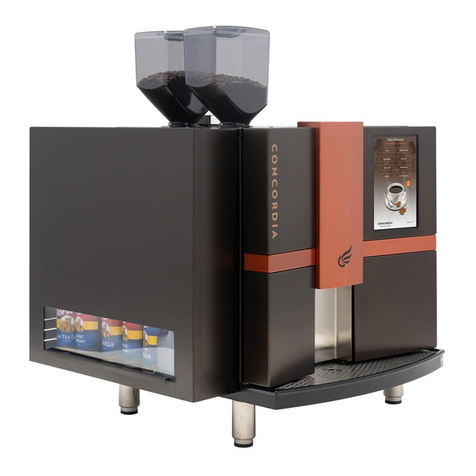
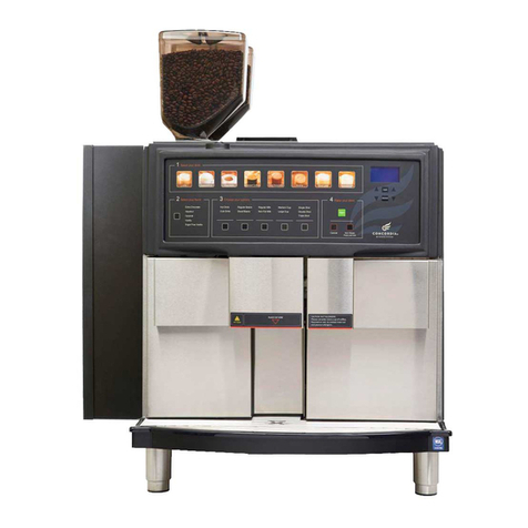
Concordia 2500s User manual

Concordia
Model
2500s/i
Super
Automatic
Espresso
Machines
Technician’s Manual


Concordia Coffee Systems
1287 120th Avenue NE
Bellevue, WA 98005
(425) 453-2800
(800) 778-0990
(425) 453-2167 Fax
http://www.concordiacoffee.com
Technical Writer and Editor: Shana McKibbin
Technical Support: Andre Belyea, Gary Williams, Pete Oksendahl, Chris
Collier
Graphic Engineer: Scott Naito
Revision A
September, 2007

Welcome to Concordia Coffee Systems!
We are very pleased to have you join our team of professionals, united
in the common pursuit of excellence on behalf of our customers.
Concordia Coffee Systems is a leader in the design, development and
manufacture of fully automated espresso systems, serving thousands of
customers throughout the world. Our goal is to continuously achieve
the highest imaginable levels of quality, service, and technological
performance for our customers. We believe that it is the ability, talent
and spirit of people like you that will enable Concordia Coffee Systems
to reach this goal.
The basic objectives of Concordia Coffee Systems are:
Deliver quality and value to our customers through leadership
and excellence in everything that we do.
Provide a strong seamless network of service to all Concordia
Coffee Systems customers while, exceeding their expectations
from us.
Build value in our employees and agents through experience,
training and the provision of opportunities for success.
Build long term value in our Company.
Be strong contributing members of the communities in which
we conduct business.
You are an important part of our team. We want to do our best to help
you find your work with Concordia Coffee Systems satisfying, rewarding
and personally meaningful. The material in this manual has been
designed to be used as a training aid, reference resource and updated
library of Concordia Coffee Systems Policies and Procedures.
It is important that you keep your manual updated to reflect our
current revisions to ensure we have provided you with the tools
necessary to facilitate YOUR success!
Ray Ross
Vice President of Service and Customer Support
Concordia Coffee Systems

Revision Change Log
Replace Old
Section With New
Section Brief Description Date 2900-233
Revision


Table of Contents
Section 1 :: Model 2500s/i Overview.................................................1-1
Model 2500i Overview Diagram........................................................ 1-2
Model 2500s Overview Diagram ....................................................... 1-3
The Model 2500s/i Components....................................................... 1-4
Touch Pad................................................................ 1-4
Electrical Encosure ..................................................... 1-4
Bean Hoppers............................................................ 1-4
Water Pump.............................................................. 1-4
Hot Water Tank ......................................................... 1-4
Brew Group .............................................................. 1-4
Steam Tank .............................................................. 1-4
Refrigeration Unit....................................................... 1-4
Grounds Bin.............................................................. 1-4
Drink Dispensing......................................................... 1-4
Grinders and the Grinder Adjustment Assembly................... 1-4
Refer/Cooling Module Assembly...................................... 1-4
Milk Valve ................................................................ 1-4
Section 2 :: Installation and Removal................................................2-1
Installation Requirements.............................................................. 2-2
Dimensions................................................................................ 2-3
Installation ............................................................................... 2-4
Placing the Unit......................................................... 2-4
Ambient Temperature.................................................. 2-4
Configuring the Machine for Supply Voltage........................ 2-4
Espresso Machine Electrical Settings ................................ 2-4
Setting the DC Jumper Plug........................................... 2-5
Configuring Transformer Auxiliary Connector #1 .................. 2-6
Connecting the Drain................................................... 2-7
Connecting the Water Supply......................................... 2-8
Problems with Reverse Osmosis Water System..................... 2-8
Connecting the Water Treatment System........................... 2-9
Starting the Machine...................................................................2-10
Consumables ............................................................................2-10
Calibration...............................................................................2-10
Customer Training......................................................................2-10
Installation Checklist ..................................................................2-11
Removal Procedures ...................................................................2-12
Cumulative Drink Total ...............................................2-12
Clean Refrigerator.....................................................2-12
Clean Brew Group & Grinders........................................2-12
Run Daily Clean Cycles................................................2-12
Disconnect Water Supply & Drain Tanks ...........................2-12
Preparation for Shipping..............................................2-13
Packaging for Shipment...............................................2-13
Section 3 :: Electrical ..................................................................3-1
Electrical Block Diagram ............................................................... 3-2
Fuses....................................................................................... 3-3
Backplane................................................................................. 3-4
AC Drawer Assembly .................................................................... 3-5
Transformer .............................................................................. 3-6
Transformer Diagrams.................................................. 3-6
Operating Voltage....................................................................... 3-7
AC Voltage ............................................................... 3-7
DC Voltage ............................................................... 3-7

Valves..................................................................... 3-7
Diodes..................................................................... 3-7
Electrical Enclosure Fan ............................................... 3-8
Power Into the Machine ................................................................ 3-9
Power into DC Power Supply Board .................................. 3-9
Power into AC Components ..........................................3-10
Setting the DC Jumper Plug (J1) ....................................3-10
Set Transformer Auxiliary Connector #1 ...........................3-11
DC Power Supply Board LEDs .........................................................3-12
Solid State Relays......................................................3-13
Jumper Plug Connector Detail........................................................3-14
Jumper Plug 1 ..........................................................3-14
Jumper Plug 2 ..........................................................3-15
Jumper Plug 3 ..........................................................3-15
Jumper Plug 6 ..........................................................3-16
Jumper Plug 7 ..........................................................3-16
Jumper Plug 8 ..........................................................3-17
Jumper Plug 10.........................................................3-17
Jumper Plug 9 ..........................................................3-18
Heater Element Wiring Diagrams ....................................................3-19
Section 4 :: Software...................................................................4-1
Software Overview...................................................................... 4-2
Main Menu Categories.................................................. 4-2
The Service Switch...................................................... 4-3
Navigating the Menu System .......................................... 4-3
Accessing the Main Menu .............................................. 4-4
Accessing a Submenu................................................... 4-4
Exiting the Menu System............................................... 4-4
Modifying a Value....................................................... 4-4
Accessing Cumulative Drink Statistics ............................... 4-5
Software Quick Reference Table...................................................... 4-6
CPU Board ...............................................................................4-11
CPU and LEDs...........................................................4-11
Calibration Overview ..................................................................4-13
Espresso Extraction....................................................4-13
The Extraction Goal ...................................................4-13
Espresso Extraction & Temperature Parameters..................4-13
Espresso Extraction Time.............................................4-13
Temperatures...........................................................4-13
How to Calibrate Espresso ............................................................4-14
Step 1: Verify Factory Settings ......................................4-14
Step 2: Use Fresh Espresso Roast Coffee Beans...................4-14
Step 3: Adjust the Coffee Grind Texture...........................4-15
Step 4: Ask Customer to Approve Extraction......................4-16
Step 5: Coffee Powder Dose and Water Volume are adjustable per
customer request ......................................................4-16
Espresso Extraction Pre-Treatment Options .......................................4-17
Pre-Treatment Options ...............................................4-17
Setting Milk and Water Timings ......................................................4-19
Latte Milk Timing ......................................................4-19
Double/Triple Latte Milk Timing ....................................4-19
Cappuccino Foamed Milk Timing ....................................4-19
Cappuccino Boost Delay ..............................................4-19
Cappuccino Coffee Delay.............................................4-19
Section 5 :: Plumbing...................................................................5-1

Water System ............................................................................ 5-2
2500s & 2500i Hydraulics Diagram ................................... 5-2
Water Supply............................................................................. 5-3
Water Filtering .......................................................... 5-3
Water Pump and Motor................................................................. 5-4
Water Pressure Gauge.................................................. 5-4
Changing Pump Pressure............................................... 5-5
Expansion Valve......................................................... 5-5
Flowmeter................................................................................ 5-5
Check Water Flow Message............................................ 5-6
Water Tank............................................................................... 5-6
Temperature/Level Probe............................................. 5-6
Level Probe .............................................................. 5-6
Temperature Probe..................................................... 5-7
Heating Elements ....................................................... 5-7
High Temperature Limit Switch ...................................... 5-7
Pressure Relief Valve................................................... 5-7
Drain Valve............................................................... 5-8
Valves ..................................................................................... 5-8
Brew Valve............................................................... 5-8
Hot Water Valve......................................................... 5-8
Water Level Sensors..................................................................... 5-9
The Steam System....................................................................... 5-9
Steam Tank Fill Valve .................................................5-10
Steam Tank .............................................................5-10
Water Level Probes....................................................5-10
Pressure Gauge.........................................................5-11
Heating Elements ......................................................5-11
Pressure Relief Valve..................................................5-11
High Temperature Limit Switch .....................................5-11
Steam Valves............................................................................5-12
Latte Steam Valve .....................................................5-12
Cappuccino Steam Valve..............................................5-12
Steam Wand Valve (if present) ......................................5-12
Captive Water Purge System.........................................5-13
Post Steam Valve.......................................................5-13
Air Purge Process ......................................................5-13
Section 6 :: The Coffee System.......................................................6-1
Coffee System Overview ............................................................... 6-2
The Espresso Path....................................................... 6-2
Grinders................................................................................... 6-3
Double Grinder Assembly.............................................. 6-3
Grinder Calibration..................................................... 6-3
Grinder Adjustment Panel............................................. 6-4
Coffee Powder Channel................................................ 6-5
Removing a Grinder .................................................... 6-5
Replacing Grinder Burrs/Blades ...................................... 6-5
Setting Grinder Adjustment Indicator to Mid-Scale ............... 6-6
Bean Hoppers ............................................................................ 6-7
Directions for Filling Bean Hopper ................................... 6-7
Inserting the Hopper Stopper ......................................... 6-7
Section 7 :: Milk System and Refrigeration Unit ...................................7-1
Milk System Overview................................................................... 7-2
Milk Delivery System Overview........................................................ 7-2
The Milk Delivery System Components............................................... 7-3

Milk Valve Assembly .................................................... 7-3
Milk Valve Solenoid and Plunger...................................... 7-3
Nozzle and Anti-Splatter Shield ...................................... 7-4
Air-Gate Valve Assembly ............................................................... 7-4
Air-Gate Valve........................................................... 7-4
Air Vent Needle ......................................................... 7-4
Connection of Milk Valve Assembly and Air-Gate Valve .......... 7-4
Alt Milk Valve ............................................................................ 7-4
The Latte Pour Process ................................................ 7-5
The Cappuccino Pour Process......................................... 7-5
Understanding the Relationship between Steam Temperature and Milk
Temperature ............................................................................. 7-5
Troubleshooting and Repair........................................... 7-6
The Milk Delivery System............................................................... 7-7
Placing Milk in the Machine ........................................... 7-7
Checking the Refrigeration Unit Temperature..................... 7-7
The Refrigeration Unit.................................................................. 7-8
Refrigeration Cooling Module Assembly.............................................. 7-9
Cold Sink Deflector ....................................................7-10
Fans.......................................................................................7-11
Interior Circulation Fan Assembly...................................7-11
Temperature Probe Assembly........................................7-11
Exterior Cooling Module Fan Assembly .............................7-12
Milk Weight Trays.......................................................................7-13
Adjusting the Milk Weight Tray......................................7-14
Milk Level Sensors......................................................7-15
Auto Milk Select........................................................7-15
Troubleshooting and Repair...........................................................7-16
Section 8:: Brew Group ................................................................8-1
The Brew Group ......................................................................... 8-2
Hall-Effect Sensors...................................................................... 8-3
Piston Movement ........................................................................ 8-4
Group Initialization ..................................................................... 8-5
Measuring Coffee Powder Dose........................................................ 8-5
Motors..................................................................................... 8-6
Right Motor .............................................................. 8-6
Left Motor................................................................ 8-6
Pistons..................................................................................... 8-7
Left Piston ............................................................... 8-7
Right Piston.............................................................. 8-8
Piston Removal Procedures ............................................................ 8-9
Left Piston Removal Procedure....................................... 8-9
Right Piston Removal Procedure...................................... 8-9
Gearbox Removal and Installation...................................................8-10
Gearbox Removal ......................................................8-10
Gearbox Installation...................................................8-10
Section 9 :: Cleaning and Maintenance..............................................9-1
Daily Maintenance of the Concordia Espresso Machine............................ 9-2
Importance of Cleaning................................................ 9-2
Concordia Cleaning Products.......................................... 9-2
Performing Daily Cleaning............................................. 9-2
Auto-Rinse ............................................................... 9-3
Preventive Maintenance................................................................ 9-3
PM Kits.................................................................... 9-3
Preventive Maintenance Checklist ................................... 9-4


Section 10 :: Concordia Procedures.................................................10-1
Concordia Coffee Systems Service Call Process ...................................10-2
Arrival to Site...........................................................10-2
Machine Repair.........................................................10-2
Hold for Parts Procedures ............................................10-2
Departing from Site....................................................10-2
Required Immediately for Call Closeout ...........................10-2
Complete Call Protocol................................................................10-3
Machine Appearance ..................................................10-3
Milk Valve ...............................................................10-3
Brew Group .............................................................10-3
Water Tank .............................................................10-3
Water Pump.............................................................10-3
Steam Tank .............................................................10-3
Refrigeration Unit......................................................10-3
Espresso Extraction....................................................10-3
Milk Pour ................................................................10-3
Service Call Checklist..................................................................10-4
Parts Return Policy.....................................................................10-5
Return Material Tag ...................................................10-6
Return Material Authorization Form ................................10-7
Form: Return Material Authorization ...............................10-8
Section 11 :: Customer Service and Training ......................................11-1
Training the Customer.................................................................11-2
Customer Training Includes ..........................................11-2
Quick Reference Guide................................................11-2
Filling Machine with Beans and Milk ................................11-2
Making a Drink..........................................................11-2
Serial Number ..........................................................11-2
Accessing Programming Menu........................................11-3
Cleaning .................................................................11-3
Ordering Cleaning Supplies...........................................11-3
Troubleshooting Tips ..................................................11-3
Calling Concordia for Assistance.....................................11-3
Concordia Coffee Systems’ Value-Added Service..................................11-4
Value-Added Service ..................................................11-4
G.U.E.S.T. ...............................................................................11-5
Greet the Customer ...................................................11-5
Understand your Customer...........................................11-6
Empathize with your customer ......................................11-7
Solve the Problem .....................................................11-8
Train the Customer....................................................11-8
Section 12 :: Messages ................................................................12-1
Troubleshooting Display Messages ...................................................12-2
Section 13 :: Troubleshooting........................................................13-1
Troubleshooting Quick Reference Guide............................................13-2
Machine Failure ........................................................13-2
Milk System .............................................................13-4
Troubleshooting Trees.................................................................13-5
Section 14 :: Parts List & Diagrams .................................................14-1
Recommended Tools List..............................................................14-2
Standard Tools .........................................................14-2
Concordia Stocked Tools..............................................14-2
Consumables............................................................14-2
Recommended Van Stock .............................................................14-3

Parts List and Diagrams................................................................14-5
Diagram 1: Overview ..................................................14-6
Diagram 1, Parts List: Overview.....................................14-7
Diagram 2: Chassis.....................................................14-8
Diagram 2, Parts List: Chassis........................................14-9
Diagram 3: Doors, 2500i ............................................ 14-10
Diagram 3, Parts List: Doors, 2500i ............................... 14-11
Diagram 4, Doors, 2500s............................................ 14-12
Diagram 4, Parts List: Doors, 2500s............................... 14-13
Diagram 5: Front Panel 2500i ...................................... 14-14
Diagram 5, Parts List: Front Panel 2500i......................... 14-15
Diagram 6: Front Panel 2500s...................................... 14-16
Diagram 6, Parts List: Front Panel 2500s......................... 14-17
Diagram 7: Top Panel ............................................... 14-18
Diagram 7, Parts List: Top Panel .................................. 14-19
Diagram 8: Grinder Assembly ...................................... 14-20
Diagram 8, Parts List: Grinder Assembly......................... 14-21
Diagram 9: Grinder Adjustment ................................... 14-22
Diagram 9, Parts List: Grinder Adjustment...................... 14-23
Diagram 10: Group Upper and Lower Piston Assy............... 14-24
Diagram 10, Parts List: Group Upper & Lower Piston Assy.... 14-25
Diagram 11: Group Drive System.................................. 14-26
Diagram 11, Parts List: Group Drive System..................... 14-27
Diagram 12: Milk Valve Assembly.................................. 14-28
Diagram 12, Parts List: Milk Valve Assembly .................... 14-29
Diagram 13: Product Delivery, 2500i ............................. 14-30
Diagram 13, Parts List: Product Delivery, 2500i ................ 14-31
Diagram 14: Product Delivery, 2500s ............................. 14-32
Diagram 14, Parts List: Product Outlet 2500s ................... 14-33
Diagram 15: Refer Module Assembly.............................. 14-34
Diagram 15, Parts List: Refer Module Assembly................. 14-35
Diagram 16: Refer Cooling Fan Assembly ........................ 14-36
Diagram 16, Parts List: Refer Cooling Fan Assembly ........... 14-37
Diagram 17: Steam Tank, Front ................................... 14-38
Diagram 17, Parts List: Steam Tank, Front ...................... 14-39
Diagram 18: Steam Tank, Rear .................................... 14-40
Diagram 18, Parts List: Steam Tank, Rear ....................... 14-41
Diagram 19: Steam Wand........................................... 14-42
Diagram 19, Parts List: Steam Wand.............................. 14-43
Diagram 20: Water Pump........................................... 14-44
Diagram 20, Parts List: Water Pump.............................. 14-45
Diagram 21: Water Tank............................................ 14-46
Diagram 21, Parts List: Water Tank............................... 14-47
Diagram 22: Water/Steam Gauge Assembly ..................... 14-48
Diagram 22, Parts List: Water/Steam Gauge Assembly........ 14-49
Section 15: Index.......................................................................15-1
Section 16: Service Bulletins.........................................................16-1

TECHNICALSUPPORT
Section 1 :: Model 2500s/i
Overview
1. Model 2500i Overview Diagram
2. Model 2500s Overview Diagram
3. The Model 2500s/i Components

Section 1: Model 2500s/i Overview 3025-001A
Model 2500i Overview Diagram
1-2 Concordia 2500s/i Technical Support Manual
2900-233

3025-001A Section 1: Model 2500s/i Overview
Model 2500s Overview Diagram
Concordia 2500s/i Technical Support Manual 1-3
2900-233

Section 1: Model 2500s/i Overview 3025-001A
The Model 2500s/i Components
Touch Pad
The touch pad provides a user interface for selecting and pouring
drinks.
Electrical Encosure
The electrical enclosure houses the CPU, AC board, and DC board.
Bean Hoppers
Each bean hopper holds approximately 2lbs of whole beans, and feeds
the beans to the grinders.
Water Pump
The water pump regulates the water pressure to 140psi during the
espresso extraction process.
Hot Water Tank
The hot water tank stores and heats the water used to brew espresso.
Brew Group
The brew group assembly precisely brews espresso, and automatically
discards the used coffee into the grounds bin.
Steam Tank
The steam tank provides steam used for steaming the milk, and for
units utilizing a steam wand.
Refrigeration Unit
The on-board refrigeration unit holds two 1-gallon milk containers.
Grounds Bin
The grounds bin catches used coffee pucks.
Drink Dispensing
The product outlet dispenses freshly brewed espresso while the
patented milk valve froths the milk.
Grinders and the Grinder Adjustment Assembly
The grinders are calibrated to grind beans according to the customer’s
desired recipe.
Refer/Cooling Module Assembly
The refer/cooling module assembly regulates the temperature inside
the refrigeration unit.
Milk Valve
Steam, air, and milk are mixed in the milk valve.
1-4 Concordia 2500s/i Technical Support Manual
2900-233

TECHNICALSUPPORT
Section 2 :: Installation and
Removal
1. Installation Requirements
2. Dimensions
3. Installation
4. Starting the Machine
5. Consumables
6. Calibration
7. Customer Training
8. Installation Checklist
9. Removal Procedures

Section 2: Installation and Removal 3025-002A
Installation Requirements
Installation site must meet specified requirements to ensure proper
machine operation.
Foot Print/Dimensions 23.48”W x 25.32”D x 36”H (23.48cm x
64.31cm x 91.44cm)
Weight 245lb (111.13kg)
Counter Space 36”W x 29”D x 42”H (91.44cm x 73.66cm x
106.68cm)
Electrical
Located within two (2) meters of machine
Single Phase:
200-240vac, 30amp dedicated circuit
NEMA L14-30 Receptacle
Three Phase:
200-240vac, 20amp, three phase dedicated
circuit
NEMA L15-30 receptacle
High Leg:
200-240vac, 30amp, high leg dedicated
circuit
International machines are shipped without a
power plug. A plug must be attached at the
time of installation and meet with all local
electrical codes.
Water
Minimum: 30psi; Maximum: 100psi (min: 2
bar, max 7 bar)
25 gallons per hour (95 liters per hour)
Cold water source with female ¼” NPT
fitting with shutoff valve
Located within five (5) feet of machine
A fresh water bypass is required for sites
with a reverse osmosis filter system.
Water Treatment System
All machines are shipped with the Scalex
Water Treatment System which includes two
combination carbon filters and water
softening cartridges.
25”H x 11”W x 5.25”D
Drain Connection for ¾” drain dose
Indirect drain required
Located within five (5) feet of machine
Ambient Air Temperature Maximum ambient temp: 90°F
2-2 Concordia 2500s/i Technical Support Manual
2900-233

3025-002A Section 2: Installation and Removal
Dimensions
Concordia 2500s/i Technical Support Manual 2-3
2900-233

Section 2: Installation and Removal 3025-002A
Installation
Installation includes machine set-up; connection to the water,
electrical and drain supplies; calibration; and customer training. If
more than one visit is required to complete the installation due to an
unprepared site, return visits are billable to the customer.
Placing the Unit
Verify counter is stable and capable of supporting at least 300lbs.
The machine height is 36”. A recommended 6” minimum additional
space is needed for pouring beans and for bean hopper removal.
Ambient Temperature
The maximum temperature of the area around a machine is 90°F. The
refrigeration unit cannot maintain a proper temperature in a location
with an ambient temperature greater than 90°F.
Do not place machine next to any equipment that exhausts hot air.
Configuring the Machine for Supply Voltage
Before connecting machine to the electrical supply, check and verify
the incoming power supply. The following chart displays the required
voltages.
2500s/i Equipped with 4 prong 220 volt plug
NEUTRAL
LEG 1 120VAC
TO NEUTRAL
NEMAL14
-30R
Receptacle
LEG 2 120VAC GROUND
NEUTRAL
TO NEUTRAL
Required Receptacle Voltages
Connections Voltage
L1 to Ground 110vac -120vac
L2 to Ground 110vac - 120vac
L1 to Neutral 110vac - 120vac
L2 to Neutral 110vac - 120vac
L1 to L2 200vac - 240vac
Ground to Neutral 0vac
Espresso Machine Electrical Settings
Prior to connecting the machine to the power source, verify all the
settings are correct. The DC jumper plug and transformer must be
properly configured.
WARNING: Failure to properly set the DC jumper plug and the
transformer connector may result in machine malfunction, short
circuit, blown fuses, overheating, or damage to the circuit boards.
2-4 Concordia 2500s/i Technical Support Manual
2900-233
This manual suits for next models
1
Table of contents
Other Concordia Coffee Maker manuals

Concordia
Concordia Integra 1 User manual

Concordia
Concordia 1500s User manual

Concordia
Concordia Integra User manual

Concordia
Concordia INTEGRA 4 User manual

Concordia
Concordia 2500i User manual

Concordia
Concordia Integra User manual

Concordia
Concordia Xpress series User manual

Concordia
Concordia XpressTouch User manual