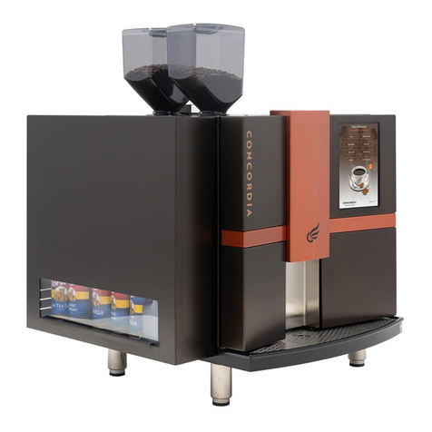
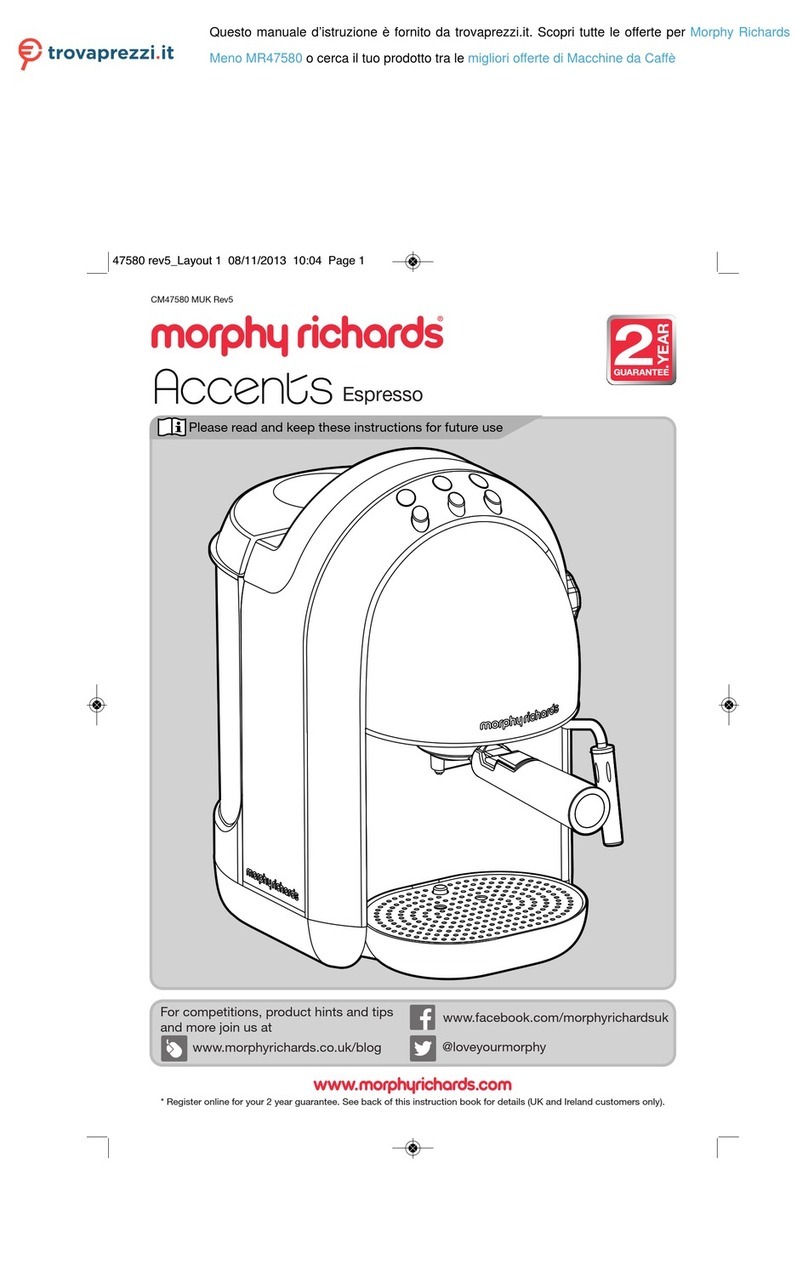
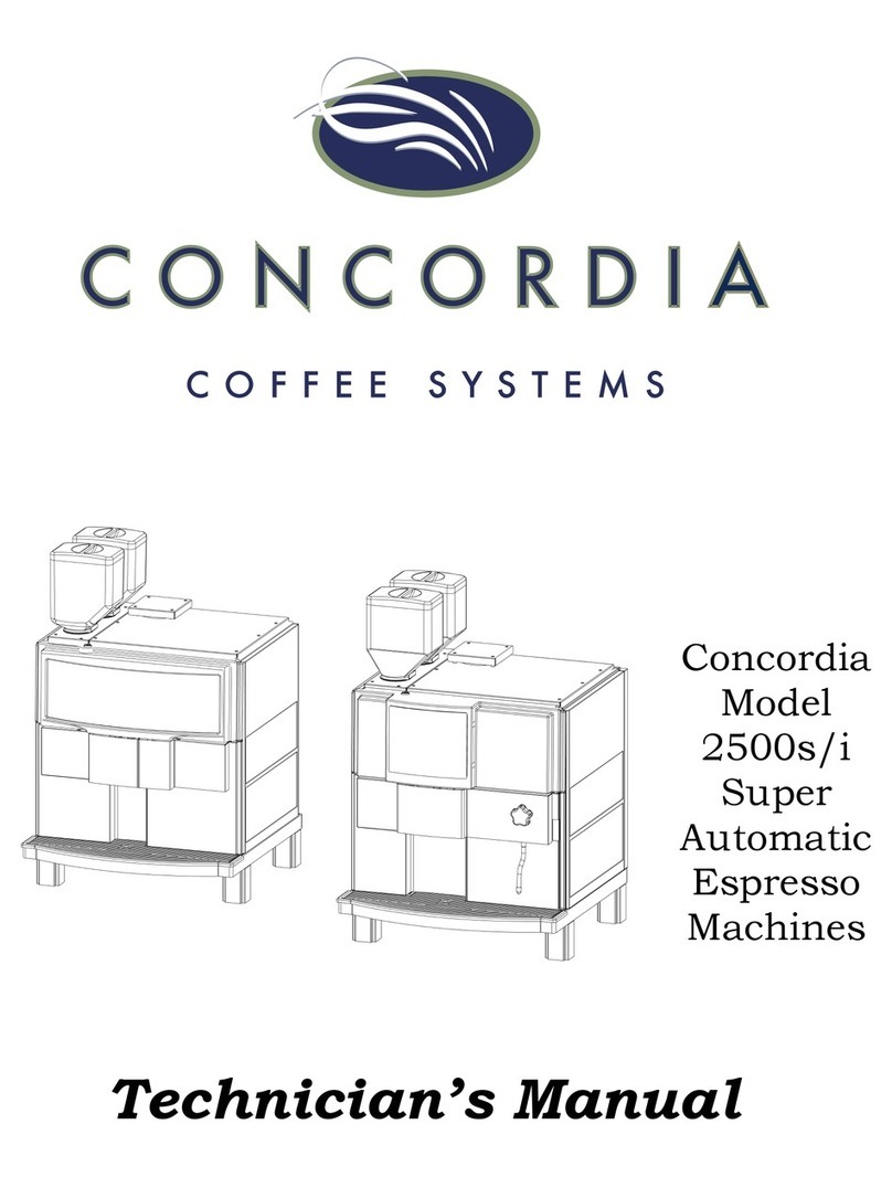
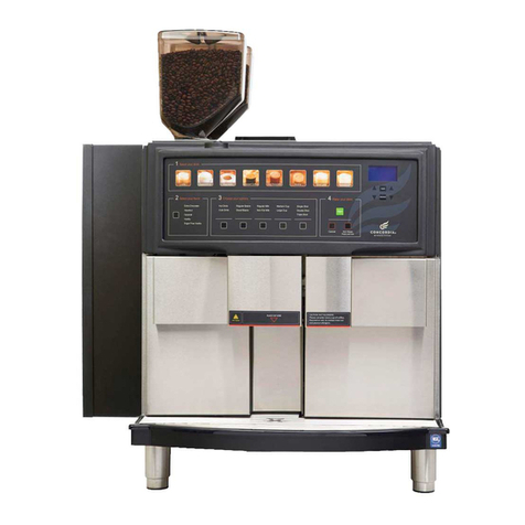
Concordia Integra User manual

Integra
Technician’s Manual


Concordia Coffee Systems
1287 120th Avenue NE
Bellevue, WA 98005
(425) 453-2800
(800) 778-0990
(425) 453-2167 Fax
http://www.concordiacoffee.com
Technical Writer and Editor: Shana McKibbin
Technical Support: Gary Williams, Gery Jaggars, Chris Collier,
Allen Moore, Dana Klatt, Dave Davis
Graphics: Quan Nguyen, Andre Belyea, Daniel Gilbert
Edition: May, 2012
2900-255B

Welcome to Concordia Coffee Systems!
We are very pleased to have you join our team of professionals,
united in the common pursuit of excellence on behalf of our
customers.
Concordia Coffee Systems is a leader in the design,
development and manufacture of fully automated espresso
systems, serving thousands of customers throughout the world.
Our goal is to continuously achieve the highest imaginable
levels of quality, service, and technological performance for our
customers. We believe that it is the ability, talent and spirit of
people like you that will enable Concordia Coffee Systems to
reach this goal.
The basic objectives of Concordia Coffee Systems are:
Deliver quality and value to our customers through
leadership and excellence in everything that we do.
Provide a strong seamless network of service to all
Concordia Coffee Systems customers while, exceeding
their expectations from us.
Build value in our employees and agents through
experience, training and the provision of opportunities
for success.
Build long term value in our Company.
Be strong contributing members of the communities in
which we conduct business.
You are an important part of our team. We want to do our best
to help you find your work with Concordia Coffee Systems
satisfying, rewarding and personally meaningful. The material
in this manual has been designed to be used as a training aid,
reference resource and updated library of Concordia Coffee
Systems Policies and Procedures.
It is important that you keep your manual updated to reflect
our current revisions to ensure we have provided you with the
tools necessary to facilitate YOUR success!

Revision Change Log
Replace
Old
Section
With
New
Section
Brief Description
Date
2900-
255
Revision

Table of Contents
Section 1 :: Integra Overview........................................... 1-1
Integra Overview ......................................................................1-2
Integra Components ..................................................................1-3
Flavor System Overview.............................................................1-4
Flavor System Components ........................................................1-5
Bin Door Assembly Components –Integra 1 and Integra 4 .............1-6
Bin Door Assembly Components –Integra 0 .................................1-7
Section 2 :: Installation and Removal ................................ 2-1
Technical Specifications and Site Requirements.............................2-2
Plumbing..................................................................................2-4
Connecting the External Drain....................................2-4
Water Supply ...........................................................2-4
Problems with Reverse Osmosis Water System.............2-5
Flavor System...........................................................................2-5
Control Box Installation .............................................2-5
Peristaltic Pump Assembly Installation.........................2-5
Chocolate Heater Assembly Installation .......................2-6
Flavor Tubing Installation ..........................................2-6
Priming the Flavor System .........................................2-7
Verify Flavor Pour Rate..............................................2-7
Additional Tasks Required at Installation ......................................2-8
Power Up the Machine...............................................2-8
Bean Hopper ............................................................2-8
Operational Configuration...........................................................2-8
Placing Milk in the Refrigeration Unit ...........................2-8
Machine Calibration ...................................................................2-9
Customer Training.....................................................................2-9
Installation Checklist .................................................................2-9
Removal Procedures ................................................................ 2-10
Section 3 :: Electrical ...................................................... 3-1
Electrical Block Diagram.............................................................3-2
Electrical Enclosure....................................................................3-3
Electrical Enclosure Fan .............................................3-4
Front Panel Cable .....................................................3-4
AC Fuses .................................................................3-4
Expansion Board (Top) ..............................................3-4
Analog (Middle) ........................................................3-4
AC/DC Power Supply.................................................3-4
Fuses ......................................................................3-5
AC/DC Power Supply Board ........................................................3-6
CPU Board................................................................................3-7
J4...........................................................................3-8
J2...........................................................................3-8
P3 ..........................................................................3-9
P4 ..........................................................................3-9
Peripheral Connections Configuration......................................... 3-10
Transformer ........................................................................... 3-11
Transformer Diagram –PN 1320-023........................3-11
Transformer Diagram –PN 1320-025........................3-11

Machine Operating Voltage ...................................... 3-12
AC Voltage.............................................................3-12
DC Voltage ............................................................ 3-12
Valves...................................................................3-12
Diodes ..................................................................3-12
Flavor System ........................................................ 3-13
DC Power Supply Board LEDs ................................................... 3-14
AC Distribution Panel ............................................................... 3-16
Jumper Plug Connector Detail ................................................... 3-17
Jumper Plug 2 ........................................................ 3-17
Jumper Plug 3, 9, 11...............................................3-18
Jumper Plug 4, 5, 6, 12 ...........................................3-19
Jumper Plug 7 ........................................................3-20
Jumper Plug 8, 10 ..................................................3-21
Troubleshooting ...................................................................... 3-22
Section 4 :: Software....................................................... 4-1
Software Overview ....................................................................4-2
Software Menu Informational Screens .........................4-2
Categories ...............................................................4-2
Service Switch .........................................................4-3
Service Switch in the RUN position..............................4-3
Service Switch in the SERVICE position .......................4-3
The Service Switch and Cleaning the Machine ..............4-3
Navigating the Menu System......................................4-4
Accessing a Sub-Category .........................................4-4
Exiting the Menu System ...........................................4-4
Accessing the Grand Total Drink Count........................4-5
Accessing Total Drink Count Statistics .........................4-5
Accessing Daily Drink Count Statistics .........................4-5
Software Quick Reference Table ..................................................4-6
Calibration ............................................................................. 4-11
Pump Pressure ....................................................... 4-12
Espresso ............................................................... 4-12
Milk Timings ..........................................................4-13
Brewed Coffee (Long Black) .....................................4-14
Flavor Timings .......................................................4-15
CPU Board.............................................................................. 4-16
Loading New Software to a Machine .......................................... 4-17
Required Equipment................................................ 4-17
Configuring HyperTerminal ...................................... 4-17
Connecting the Laptop to the Machine.......................4-24
Updating Software for Customers with Custom Drink
Recipes .................................................................4-27
Section 5 :: Plumbing ...................................................... 5-1
The Water System.....................................................................5-2
Water Supply............................................................................5-3
Line Pressure ...........................................................5-3
Check Valve .............................................................5-3
Water Filtration System.............................................5-3
Reverse Osmosis Water System .................................5-3
Expansion Valve........................................................................5-4
Water Pump and Motor Assembly ................................................5-4
Flowmeter ................................................................................5-5
Hot Water Tank.........................................................................5-6
Pressure Relief Valve.................................................5-7
Temperature/Level Probe ..........................................5-7
Level Probe..............................................................5-7
Temperature Probe ...................................................5-8
Drain Valve..............................................................5-8
Water Out ...............................................................5-8
Brew Valve ..............................................................5-8
Heating Elements .....................................................5-9
High Temperature Limit Switch –Water ......................5-9
Draining the Water Tank............................................5-9
Valve Tree.............................................................................. 5-10
Valve Tree Removal ................................................ 5-11
Valve Tree Replacement ..........................................5-13
The Steam System .................................................................. 5-14
Steam Tank............................................................................ 5-15
Steam Valves.........................................................5-16
High Temperature Limit Switch –Steam.................... 5-16
Heating Elements ...................................................5-16
Water Level Probes ................................................. 5-17
Pressure Relief Valve...............................................5-17
Safety Probe ..........................................................5-18
Vacuum Break Valve ...............................................5-18
Draining the Steam Tank ......................................... 5-18
Front Panel Assembly .............................................................. 5-19
Steam Pressure Gauge ............................................ 5-19
Water Pressure Gauge............................................. 5-20
Setting Pump Pressure ............................................5-20
Check Water Flow Message ...................................... 5-20
Troubleshooting ...................................................................... 5-20
Section 6 :: Coffee System............................................... 6-1
Coffee System Overview ............................................................6-2
Fresh Water Supply ..................................................6-3
Water Pump / Motor Assembly ...................................6-3
Flowmeter ...............................................................6-3
Hot Water Tank ........................................................6-3
Brew Valve Assembly ................................................6-3
Brew Group .............................................................6-3
Grounds Chute .........................................................6-3
Upper Piston ............................................................6-4
Lower Piston ............................................................6-4
Bean Hopper ............................................................6-4
Grinder ...................................................................6-4
Grounds Bin.............................................................6-4
Espresso Nozzle .......................................................6-4
Bean Grinders...........................................................................6-5
Calibration: Espresso Grind........................................6-6
Replacing Bean Grinder Burrs/Blades ..........................6-7
Coffee Powder Channel..............................................6-7
Bean Hoppers ...........................................................................6-8
Inserting the Hopper Stopper .....................................6-8
Brew Group Overview ................................................................6-9

Upper Piston .......................................................... 6-10
Grounds Chute ....................................................... 6-10
Sweep Arm ............................................................6-10
Brew Chamber ....................................................... 6-10
Thermal Switch ......................................................6-10
Brew Block ............................................................6-10
Brew Chamber Heater .............................................6-10
Grounds Bin...........................................................6-10
Empty Grounds Bin .................................................6-11
Troubleshooting ...................................................................... 6-11
Section 7 :: Milk System and Refrigeration System ............. 7-1
Milk Delivery System Overview ...................................................7-2
Milk Delivery System Components...............................................7-3
Milk Pump Assembly .................................................7-3
Pick-Up Screen.........................................................7-3
Air Check Valve ........................................................7-3
Milk Pick-Up Tube .....................................................7-3
Product Delivery Nozzle.............................................7-3
Vacuum Break Valve .................................................7-3
The Drink Pour Process ..............................................................7-4
Latte.......................................................................7-4
Cappuccino ..............................................................7-4
Milk System Theory of Operation.................................................7-4
Basic Terminology ....................................................7-4
Initial Setup of the Milk System ..................................7-5
Milk System Capabilities ............................................7-6
A Common Milk Timing Mistake ..................................7-6
Air Gate Valve Assembly ............................................................7-7
Air Gate Valve ..........................................................7-7
Air Vent Valves.........................................................7-8
Air Vent Needles.......................................................7-8
Milk Flow Sensor .......................................................................7-9
Adjusting the Milk Flow Sensor ...................................7-9
Cappuccino Temperature Adjustment Valve ................................ 7-11
Mixing TEE.............................................................7-11
Refrigeration Unit .................................................................... 7-12
Placing Milk in the Machine ......................................7-12
Checking the Refrigeration Unit Temperature .............7-13
Refrigeration Unit Overview ...................................................... 7-13
Milk Pump Assembly ...............................................7-13
Refrigeration Cooling Module Assembly .....................7-14
Cold Sink Plenum ...................................................7-15
Interior Fan Assembly .............................................7-15
Refrigeration Unit Temperature Probe Assembly .........7-15
Milk Pick-Up Tube ................................................... 7-15
Exterior Cooling Module Fan Assembly ......................7-16
Troubleshooting ...................................................................... 7-16
Section 8 :: Flavor System ............................................... 8-1
Flavor System Overview.............................................................8-2
Chocolate Sauce Delivery Path ...................................8-2
Syrup Delivery Path ..................................................8-3
Flavor Lines .............................................................8-4

Chocolate Heater Assembly........................................8-4
Chocolate Sauce.......................................................8-5
Flavor Storage Area...................................................................8-5
Connecting Flavor Tubing ..........................................8-6
Changing Flavor Boxes ..............................................8-7
Changing the Flavor Pour Rate ....................................................8-8
Verifying Proper Syrup Flow ..................................... 8-10
Peristaltic Pumps..................................................................... 8-10
Syrup Manifold........................................................................ 8-11
Replacing the Syrup Manifold ...................................8-12
Cleaning the Flavor System ...................................................... 8-14
Priming the Flavor System........................................................ 8-15
Troubleshooting ...................................................................... 8-16
Section 9 :: Steam Wand ................................................. 9-1
Steam Wand Overview...............................................................9-2
ON/OFF Button.........................................................9-2
Installation ...............................................................................9-2
Valves .....................................................................................9-2
Replacing the Steam Wand Button ..............................................9-3
Replacing a Steam Wand............................................................9-3
Removing a Steam Wand ..........................................9-3
Troubleshooting ........................................................................9-3
Cleaning the Steam Wand ..........................................................9-4
Section 10 :: Cleaning and Maintenance............................10-1
Routine Machine Maintenance ................................................... 10-2
Daily Maintenance ..................................................10-2
Monthly Maintenance ..............................................10-2
Concordia Cleaning Products .................................... 10-2
Cleaning Timers ...................................................................... 10-3
Preventive Maintenance ........................................................... 10-3
Section 11 :: Concordia Procedures ..................................11-1
Concordia Coffee Systems Service Call Protocol .......................... 11-2
Arrival to Site......................................................... 11-2
Machine Repair.......................................................11-2
Hold for Parts Procedures ........................................ 11-2
Departing from Site ................................................11-2
Required Immediately for Call Closeout .....................11-3
Complete Call Protocol ............................................................. 11-3
Machine Appearance ...............................................11-3
Brew Group ........................................................... 11-3
Water Tank............................................................11-3
Water Pump...........................................................11-3
Steam Tank ...........................................................11-3
Refrigeration Unit ...................................................11-3
Espresso Extraction ................................................11-3
Milk Pour ............................................................... 11-3
Service Call Checklist............................................................... 11-4
Parts Return Policy for Non-Consignment Agents......................... 11-5
Parts Return Policy for Consignment Agents ............................... 11-5
Return Material Tag ................................................11-6
Parts Replenishment Form........................................................ 11-7
Section 12 :: Customer Service and Training .....................12-1

Training the Customer ............................................................. 12-2
Customer Training Includes .....................................12-2
User Guide ............................................................12-2
Filling Machine with Beans and Milk ..........................12-2
Making a Drink ....................................................... 12-2
Serial Number ........................................................12-2
Accessing the Software Menu ...................................12-2
Cleaning ................................................................ 12-3
Ordering Cleaning Supplies ......................................12-3
Troubleshooting Tips...............................................12-3
Calling Concordia for Assistance ...............................12-3
Concordia Coffee Systems’ Value-Added Service ......................... 12-4
Value-Added Service ...............................................12-4
G.U.E.S.T. .............................................................................. 12-6
Greet the Customer ................................................12-6
Understand your Customer ......................................12-7
Empathize with the Customer .................................. 12-8
Solve the Problem ..................................................12-9
Train the Customer .................................................12-9
Section 13 :: Messages ...................................................13-1
Troubleshooting Display Messages............................................. 13-2
Section 14 :: Troubleshooting ..........................................14-1
Troubleshooting Quick Reference Guide ..................................... 14-2
Machine Failure ......................................................14-2
Coffee System........................................................ 14-3
Flavor System ........................................................ 14-4
Milk System ...........................................................14-4
Troubleshooting Trees ............................................................. 14-5
Electrical System –CHK ANALOG BOARD ..................14-6
Electrical System –CHECK STATS ............................14-7
Electrical System –CHECK CLOCK ............................14-8
Electrical System –AC Board Failures .......................14-9
Electrical System –Incorrect Software for Touchpad. 14-10
Electrical System –Repeated CHECK MILK Error ...... 14-11
Electrical System –NOT CONFIGURED .................... 14-12
Electrical System –Card Swipe or Tap Not Authorized...14-
13
Electrical System –No Display on Card Reader......... 14-14
Electrical System –LOAD DISP DATA and LOAD SEQ DATA
.......................................................................... 14-15
Electrical System –DC Board Failures –PAGE 1 ....... 14-16
Electrical System –DC Board Failures –PAGE 2 ....... 14-17
Electrical System –FRONT PANEL FAILED................ 14-18
Coffee System –Initialize Group ............................ 14-19
Coffee System –Extended PLEASE WAIT Message –PAGE
1 ........................................................................ 14-20
Coffee System –Extended PLEASE WAIT Message –PAGE
2 ........................................................................ 14-21
Coffee System –CHECK WTR FLOW –PAGE 1 .......... 14-22
Coffee System –CHECK WTR FLOW PAGE 2............. 14-23
Coffee System –OUT OF BEANS / NO GROUNDS...... 14-24
Coffee System –Slow Espresso Pour....................... 14-25

Coffee System –Upper Piston Stuck in Up/Chamber
Position –PAGE 1 ................................................. 14-26
Coffee System –Upper Piston Stuck in Up/Chamber
Position –PAGE 2 ................................................. 14-27
Milk System –Cold Milk Pour –PAGE 1 ................... 14-28
Milk System –Cold Milk Pour –PAGE 2 ................... 14-29
Milk System –Milk Overpour –PAGE 1................... 14-30
Milk System –Milk Overpour PAGE 2 ...................... 14-31
Milk System –No Milk Pour –PAGE 1...................... 14-32
Milk System –No Milk Pour –PAGE 2...................... 14-33
Milk System –Short Pour Milk –PAGE 1 .................. 14-34
Milk System –Short Pour Milk –PAGE 2 .................. 14-35
Refrigeration System –REFR TEMP HI –PAGE 1 ....... 14-36
Refrigeration System –REFR TEMP HI –PAGE 2 ....... 14-37
Refrigeration System –REFR TEMP LO .................... 14-38
Refrigeration System –REFR DOOR OPEN ............... 14-39
Steam System –CHK SENSOR VOLTAGE ................. 14-40
Steam System –CHK STEAM PROBES ..................... 14-41
Steam System –Steam High Limit.......................... 14-42
Steam System –STEAM TEMP HI ........................... 14-43
Steam System –STEAM TEMP LO –PAGE 1 ............. 14-44
Steam System –STEAM TEMP LO –PAGE 2 ............. 14-45
Steam System –No Steam During Milk Pour –PAGE 1 ..14-
46
Steam System –No Steam During Milk Pour –PAGE 2 ..14-
47
Steam System –No Steam During Milk Pour –PAGE 3 ..14-
48
Steam System –CHECK STEAM TANK ..................... 14-49
Flavor System –Cross-Contamination of Flavors ...... 14-50
Flavor System –Not Enough Flavor ........................ 14-51
Flavor System –No Flavor in Drink –PAGE 1 ........... 14-52
Flavor System –No Flavor in Drink–PAGE 2 ............ 14-53
Flavor System –Too Much Flavor in Drink ............... 14-54
Water System –CHK WATER SUPPLY –PAGE 1 ........ 14-55
Water System –CHK WATER SUPPLY –PAGE 2 ........ 14-56
Water System –Water Tank Limit Switch Open –PAGE 1
.......................................................................... 14-57
Water System –Water Tank Limit Switch Open –PAGE 2
.......................................................................... 14-58
Water System –WATER TEMP HI............................ 14-59
Water System –WATER TEMP LO ........................... 14-60
Section 15 :: Parts List & Diagrams ..................................15-1
Recommended Tools List .......................................................... 15-2
Standard Tools .......................................................15-2
Concordia Stocked Tools.......................................... 15-2
Consumables ......................................................... 15-2
Parts List and Diagrams ........................................................... 15-3
Diagram 1: Machine Overview..................................15-4
Diagram 1, Parts List: Machine Overview...................15-5
Diagram 2: Bin Door Assembly.................................15-6
Diagram 2, Parts List: Bin Door Assembly..................15-7
Diagram 3: Refrigeration Unit Door...........................15-8

Diagram 3, Parts List: Refrigeration Unit Door............15-9
Diagram 4: Front Panel ......................................... 15-10
Diagram 4, Parts List: Front Panel .......................... 15-11
Diagram 5: Grinder Assembly ................................ 15-12
Diagram 5, Parts List: Grinder Assembly ................. 15-13
Diagram 6: Brew Group Assembly .......................... 15-14
Diagram 6, Parts List: Brew Group Assembly ........... 15-15
Diagram 7: Milk Delivery System............................ 15-16
Diagram 7, Parts List: Milk Delivery System ............. 15-17
Diagram 8: Refrigeration Unit Module Assembly ....... 15-18
Diagram 8, Parts List: Refrigeration Unit Module Assembly
.......................................................................... 15-19
Diagram 9: Steam Tank Assembly .......................... 15-20
Diagram 9, Parts List: Steam Tank Assembly ........... 15-21
Diagram 10: Water Tank ....................................... 15-22
Diagram 10, Parts List: Water Tank Assembly .......... 15-23
Diagram 11: Electrical Enclosure ............................ 15-24
Diagram 11, Parts List: Electrical Enclosure ............. 15-25
Diagram 12: Sauce Delivery System ....................... 15-26
Diagram 12, Parts List: Sauce Delivery System ........ 15-27
Diagram 13: Milk Pump Assembly........................... 15-28
Diagram 13, Parts List: Milk Pump Assembly............ 15-29
Diagram 14: Flowmeter......................................... 15-30
Diagram 14, Parts List: Flowmeter.......................... 15-31
Diagram 15: Water Pump Assembly ........................ 15-32
Diagram 15, Parts List: Water Pump Assembly ......... 15-33
Section 16 :: Index ........................................................16-1
Section 17 :: Service Bulletins .........................................17-1
Service Bulletins ..................................................................... 17-3

Section 1 :: Integra Overview
1. Integra Overview
2. Integra Components
3. Flavor System Overview
4. Flavor System Components
5. Bin Door Assembly –Integra 1 and 4
6. Bin Door Assembly Components –Integra 1
and 4
7. Bin Door Assembly –Integra 0
8. Bin Door Assembly Components –Integra 0
T E C H N I C A L S U P P O R T

Section 1: Integra Overview 3029-001B
1-2 Concordia Integra Technical Support Manual
2900-255B
Integra Overview
SYRUP

3029-001B Section 1: Integra Overview
Concordia Integra Technical Support Manual 1-3
2900-255B
Integra Components
Air Gate Valve Assembly
The air gate valve assembly allows a regulated supply of air to
mix with the milk inside the milk pump assembly.
Milk Pump Assembly
The milk pump assembly draws milk from the milk container.
Bean Hopper
Each bean hopper holds whole espresso roast beans and feeds
the beans to the grinders.
Refrigeration Module Assembly
The refrigeration module assembly regulates the temperature
inside the refrigeration unit.
CPU Assembly
The CPU assembly controls all machine functions.
AC/DC Power Supply
The AC/DC power supply board provides the voltage for the
machine.
Syrup Manifold
Syrup is infused into drinks via the syrup manifold.
Brew Group
The brew group assembly brews espresso and automatically
discards the used coffee into the grounds bin.
Water Pump
The water pump regulates the water pressure to 140psi during
the espresso extraction process.
Grinders (Left and Right)
The grinders are calibrated to grind espresso beans according
to the customer’s recipe.
Valve Tree Assembly
The valve tree assembly houses the hot water valve, steam fill
valve, chocolate purge valve, and steam tank purge valve.
Hot Water Tank
The hot water tank stores and heats the water used to brew
espresso.
Steam Tank
The steam tank provides steam used for steaming the milk.

Section 1: Integra Overview 3029-001B
1-4 Concordia Integra Technical Support Manual
2900-255B
Flavor System Overview
115 VAC
CONTROL
UNIT
POWER
SUPPLY
WATER
SUPPLY
INPUT
PUMP UNIT
19"W x 13"D x 9"H
WATER
FILTER
208 VAC
DRAIN
FLAVOR
BOXES
6.25"
9.5"
15.5"
FLAVOR BOX
DIMENSIONS
4'
10'
115 VAC
SYRUP RACK
WITH WARMING MAT
12"
16"
32" / 82 cm
12" / 305 mm

3029-001B Section 1: Integra Overview
Concordia Integra Technical Support Manual 1-5
2900-255B
Flavor System Components
Integra 1 and Integra 4 only
Pump Unit
The pump unit is the assembly of peristaltic pumps that moves
the product from the box to the syrup manifold.
Control Unit
The control unit houses the electronic board, which controls the
syrup pumps.
Power Supply
The power supply provides power to the control unit.
Chocolate Heater Assembly
The chocolate heater assembly provides heat to the flavor tray
used for chocolate sauce, to ensure a minimum temperature of
85 F/29 C is maintained.
Syrup Rack
The flavor boxes are placed on syrup racks, in the designated
flavor storage area.

Section 1: Integra Overview 3029-001B
1-6 Concordia Integra Technical Support Manual
2900-255B
Bin Door Assembly Components –Integra 1 and
Integra 4
1. Syrup Manifold –Steam, air, milk, and syrup are
mixed in the syrup manifold.
2. Milk Input Tube –The milk input tube introduces milk
to the syrup manifold.
3. Flavor Tubes –INTEGRA 4 ONLY
The syrup tubes transfer syrup from the flavor boxes to
the syrup manifold. The flavor lines utilize the same
color coding that is present on the flavor boxes.
4. Chocolate Sauce Tube –The chocolate sauce tube
transfers chocolate sauce from the chocolate sauce box
to the syrup manifold. The chocolate sauce tube utilizes
the same color coding that is present on the chocolate
sauce box.
5. Milk Output Tube –Once milk and any flavor have
been mixed on the syrup manifold, the milk output tube
transfers the milk mixture to the product delivery output
and into the customer’s cup.
6. Product Delivery Outlet –The product delivery outlet
dispenses drinks and hot water.
7. Display Board –The display board provides power to
the menu board on the front of the machine.
1
2
5
3
4
7
6
Other manuals for Integra
1
Table of contents
Other Concordia Coffee Maker manuals

Concordia
Concordia 1500s User manual

Concordia
Concordia Integra 1 User manual

Concordia
Concordia 2500i User manual

Concordia
Concordia Xpress series User manual

Concordia
Concordia 2500s User manual

Concordia
Concordia INTEGRA 4 User manual

Concordia
Concordia XpressTouch User manual

Concordia
Concordia Integra User manual