ES-R-2x01B-M RS-232 to RS-422/RS-485 Converters Manual
Version 1.2
Document Reference No.: CP_000047 Clearance No.: CP#037
Copyright © Connective Peripherals Pte Ltd 4
2Specification
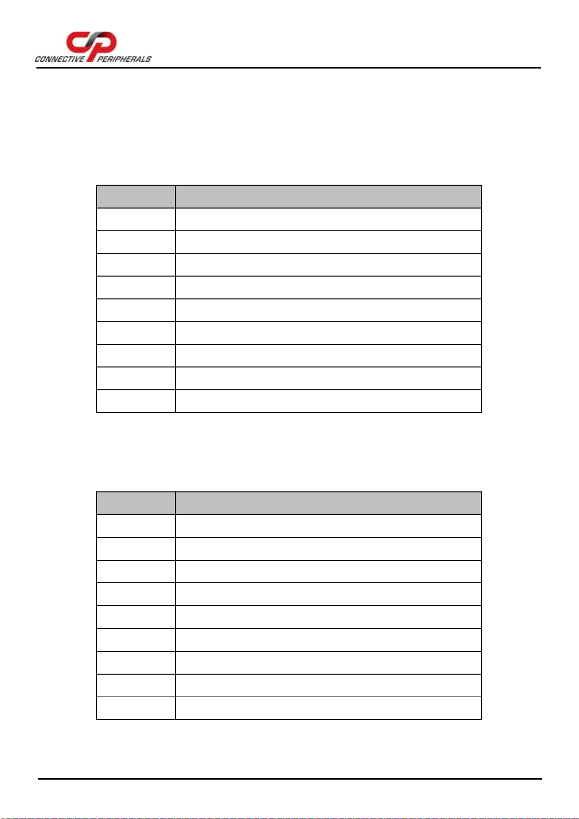
RS-232 to RS-422/RS-485 Converter (ES-R-2001B-M)
Converts RS-232 port to high speed RS-422 / RS-485 port
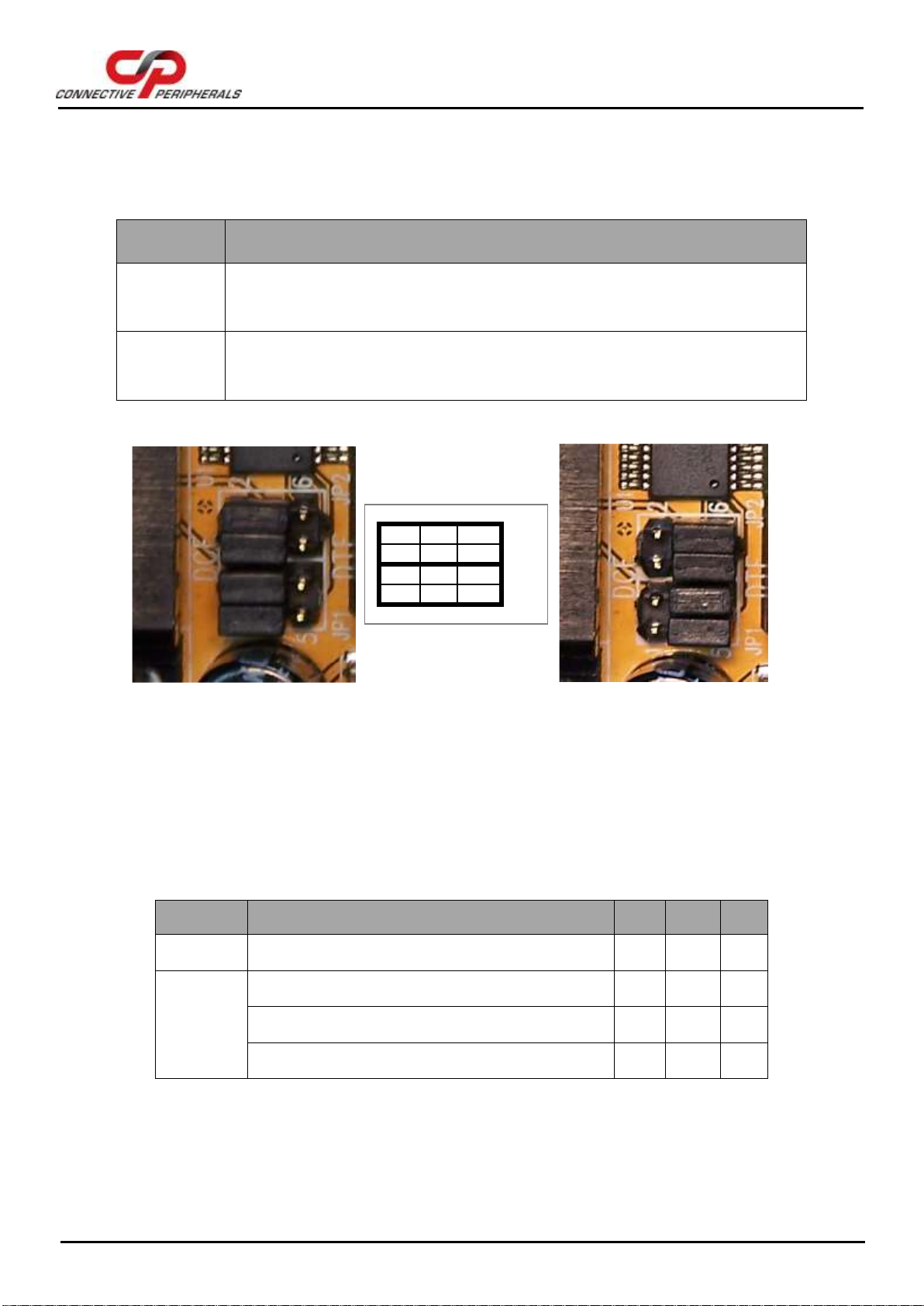
RS-232 port can be selected to DCE or DTE pin assignment
Data rate: 300 bps to 1M bps
RS-232 connector: One DB-9 female connector
RS-422 / RS-485 connector: One DB-9 male connector and one 5-pin terminal block
Auto transmit/receive control for 2-wire RS-485 half-duplex operation
Termination and bias resistors installed on-board and selectable by jumpers
RS-422 data signals : TX-, TX+, RX+, RX-, GND, RTS-, RTS+, CTS+, CTS-
RS-485 data signals (full-duplex) : TX-, TX+, RX+, RX-, GND
RS-485 data signals (half-duplex) : Data-, Data+, GND
LEDs indicate TxD and RxD
Wide input power range : 9V DC to 48V DC
Operating temperature range : –200C to 600C
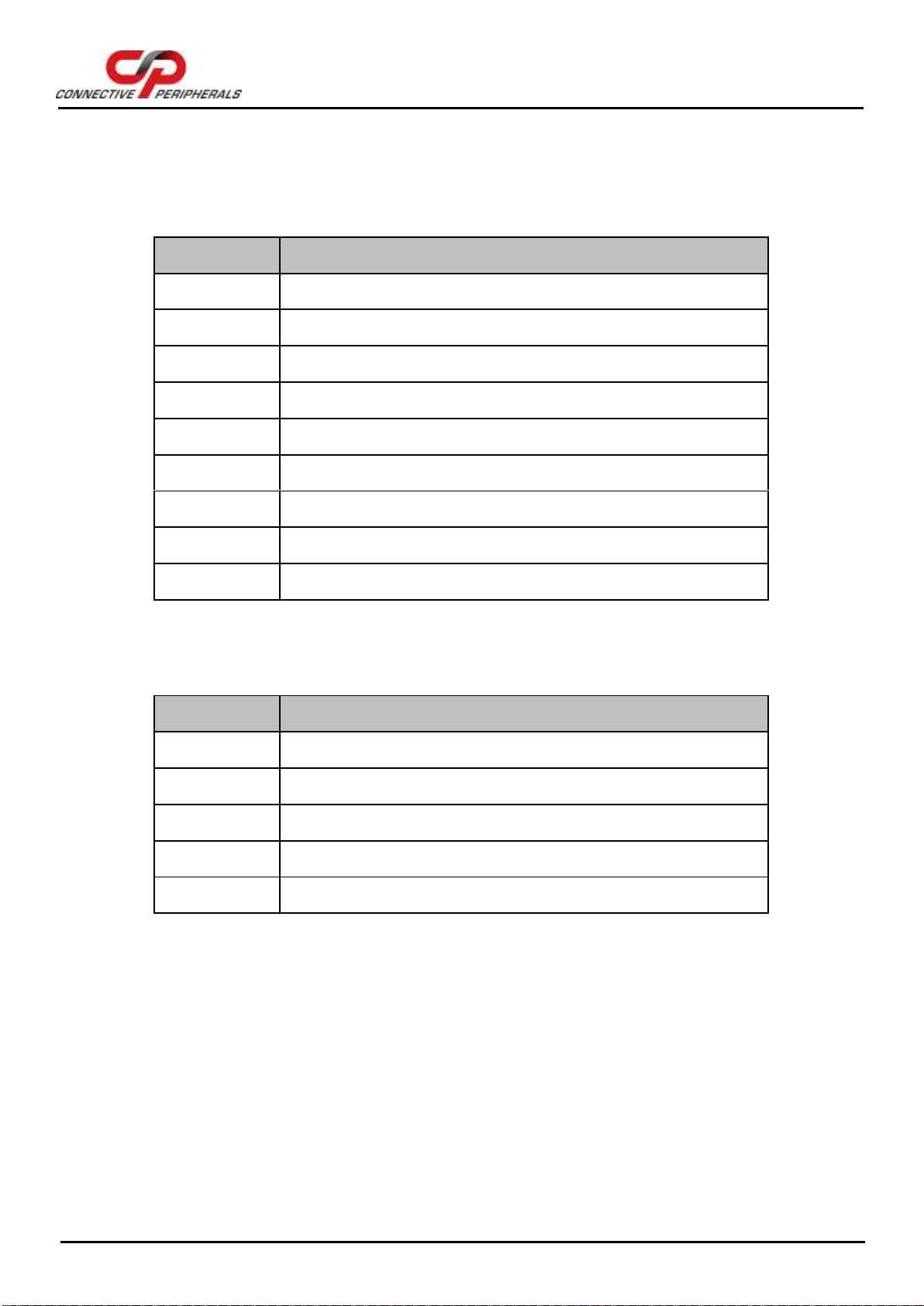
Opto-isolated RS-232 to RS-422/RS-485 Converter (ES-R-2101B-M)
Converts RS-232 port to high speed RS-422 / RS-485 port
RS-232 port can be selected to DCE or DTE pin assignment
RS-422/RS-485 port is optically isolated with 2000 Volt DC optical isolation
RS-422/RS-485 port is surge protected on all signal lines to withstand electrostatic discharge
and power surges up to 25KV ESD
Data rate: 300 bps to 1M bps
RS-232 connector: One DB-9 female connector
RS-422 / RS-485 connector: One DB-9 male connector and one 5-pin terminal block
Auto transmit/receive control for 2-wire RS-485 half-duplex operation
Termination and bias resistors installed on-board and selectable by jumpers
RS-422 data signals : TX-, TX+, RX+, RX-, GND, RTS-, RTS+, CTS+, CTS-
RS-485 data signals (full-duplex) : TX-, TX+, RX+, RX-, GND
RS-485 data signals (half-duplex) : Data-, Data+, GND
LEDs indicate TxD and RxD
Wide input power range : 9V DC to 48V DC
Operating temperature range : –200C to 600C