Conotec CNT-2003SV User manual

1. Cautions for safety
Be sure to read cautions before use for correct use.
* The specifications and exterior sizes described in this manual may be subject to change for
improving product capacity.
1. This product was not manufactured as a safety device. Therefore, in case of using it as a
controller such as for a device that may cause casualty, serious damage to peripheral
devices, and tremendous loss of property, be sure to attach double safety devices.
2. Do not do wiring or inspect or repair while power is on.
3. In case of supplying power, be sure to check a terminal number for connection.
4. This device should not be dissembled, processed, improved, or repaired.
Before the installation of this device, understand fully how to use, safety regulations or
warnings, and be sure to use within specified related specifications or related capacities.
Do not do wiring or install it for a motor or solenoid with great inductive load.
During the extension of a sensor, use a shielding wire, and do not make it unnecessarily
longer.

Do not use the same power supply or any part that generates arc during closing or
opening directly near the power supply.
A power line should be far apart from a high-tension wire, and the device should not be
installed in a place containing much water, oil, or dust.
Do not install it in a place under direct light or exposed to rain.
Do not install it in a place with strong magnetism or noise or vibration or impact.
Put it far apart from a place that may release strongly alkaline or strongly acidic
substance, and use an independent pipe.
Do not spray water directly on it for cleaning in case of installing it in the kitchen.
Do not install it in a place where temperature/humidity exceeds rating.
Take caution not to break a sensor wire or make any scratch.
A sensor wire should be away from a signal line, power, and load line, and use an
independent pipe.
In case of dissembling or modifying this product voluntarily, it may not be applied with
warranty service.
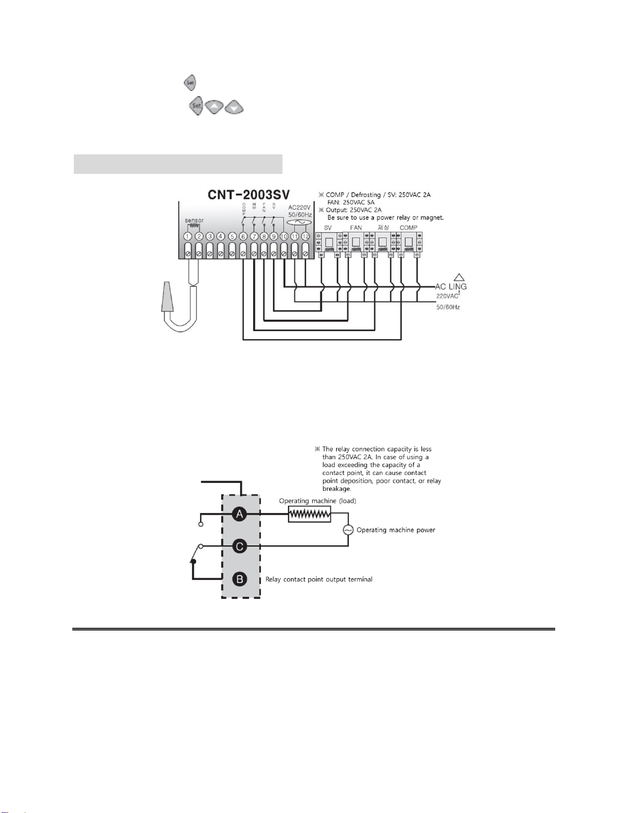
A mark on the terminal circuit diagram is a safety mark as warning or caution.
Do not use it near any device (harmonics welder, harmonics, harmonics radio, and large
capacity SCR controller) that generates strong harmonics noise.
In case of using it with any other method than one designated by a manufacturer, injury
or loss of properties may occur.
As it is not a toy, keep out of the reach of children.
Installation must be done by a relevant professional or a qualified person.
Our company shall not be responsible for any damage caused by failing to observe the
contents specified in the above warnings or cautions or by the fault of a consumer.
Caution, danger regarding electric impact
Electric impact –Do not connect it to an AC terminal during a current flow. It may
experience any electric impact.

During the check of input power, be sure to cut off input power.
2. Model configuration
Model
Sensor
Control output
Temperature scope
Function
CNT-2003SV
(exclusively for
cooling)
NTC
Relay contact
point
Celsius:
-55.0℃~ +99.9℃
Solenoid valve,
COMP,
defrosting, Fan
control
3. Part name
Product exterior and each part name
1. Heater/LTS (low temperature
prevention) indication
2. Solenoid valve output indication
3. Eva fan (에바휀) output indication
4. Defrosting output indication
5. COMP output indication
6. Defrosting switch
7. Increase switch
8. Function change switch
9. Decrease switch
User mode change (temperature setup)
Set temperature change of main output
If pressing key, a setup value will flicker on the screen.
The setup value can be increased or decreased by key or key.
Setter mode function setup

If pressing key for over 5 seconds, it will turn into a setter mode, and change it in
the order of .
4. Terminal circuit diagram
Example of relay connection
※The relay connection capacity is less than 250VAC 2A. In case of using a load exceeding
the capacity of a contact point, it can cause contact point deposition, poor contact, or relay
breakage.

5. Order of set value change
========================================================================

6. Detailed explanation of functions
: Deviation temperature setup
For ON/OFF control, a certain gap between ON and OFF is required (ON/OFF gap
setup)
If ON and OFF operates too often, a relay or other output contact point may be damaged
quickly or hunting (power generation, chattering) may occur by outside noise.
To prevent these phenomena, deviation temperature setup for use functions to protect a
contact point of a device or others.
Setup/cancellatio
n
(Cooling operation)
(Heating operation)
Plus deviation
direction setup
Bilateral deviation
direction setup
: Delayed time for output operation
Use when a problem occurs by frequent repetition of ON/OFF operations of a target to
control (including a cooler and a compressor)
Protects machine in operation during momentary power outage or power resupply

Ex) When will the output be ON when set
temperature is 25.0℃, set value is
1.30, and set value is 1.0℃?
The current temperature increases, and
when it exceeds 26.0℃at B position, the
relay is on at C position after 1 minute and
30 seconds, a set time of . The reason
why the output delayed time is applied not
from A position but from B position is
because hysteresis (deviation) gap
is set as 1.0℃.
: COMP operation form setup
: Electronic valve COMP simultaneous operation according to temperature
: An electronic valve is OFF according to temperature and COMP is OFF after COMP
stop delayed time.
: COMP OFF delayed time
COM is OFF after an electronic valve is OFF and after a set time
Ex: : when it is 10 seconds
: current temperature correction
Despite no problem of a product, it corrects an error occurring with a sensor entered
outside as well as a temperature when the temperature is different from a standard
temperature (ex, a mercury thermometer or currently used thermometer and thermostat)

Ex: Actual temperature: 25.0℃
Display screen: 28.0℃
When there is more than 3℃difference from actual temperature
If is corrected from 0.0 -> -3.0, it is displayed as 25.0℃on the screen.
: defrosting stop time
If the setup range is 0~250 hours of defrosting cycle, it begins defrosting.
* Defrosting is stopped when it is set as 0.
: defrosting time
If the setup range is 0~250 hours of defrosting cycle, it begins defrosting.
Defrosting operation is repeated for 10 minutes every 4 hours.
* Defrosting is stopped when it is set as 0.
: FAN On delayed time after defrosting
Setup range 0.00~9.59 (minute, second)
Ex) : 0.30 (30 seconds)

: Temperature for low temperature prevention
If setup temperature is 0, a low temperature prevention function is OFF.
If the current temperature is below (set value –), FAN is ON
(During the operation of function, defrosting and FAN are output immediately
regardless of the setup of fan below)
: See to a table for the program setup of FAN setup (F1~F4)
※Table
COMP ON
COMP OFF
Defrosting
FAN
operation
F1
ON
OFF
OFF
F2
ON
ON
ON
F3
ON
OFF
ON
F4
ON
ON
OFF
Manual defrosting setup method
1. Manual defrosting ON: If pressing a key for more than 3 seconds, K2 LED is lit and
manual defrosting begins. On the display screen, and remaining defrosting time are
displayed alternatively.
2. Manual defrosting OFF: If pressing a key again for more than 3 seconds while
manual defrosting is ON, it is IFF. Or it is completed automatically after time
: COMP accumulated time defrosting selection on: Defrosting by accumulated COMP
oFF: cycle defrosting
* If COMP accumulated time is over (defrosting time) set time, defrosting begins.
: If pressing key on reset setup mode and pressing after selecting with
a key, it is initialized. Then, a product model name is displayed and a current
temperature is displayed afterwards.
Caution: since all set values except for are initialized, use after double-check.
========================================================================

7. Setup range and set values during delivery
Display
Function
Scope
Set value
during
delivery
Remarks
Temperature setup
Deviation temperature
setup
Hysterie (deviation)
temperature setup
Output operation
delayed time setup
Minute, second
Operation method setup
COMP OFF delayed
time
Minute, second
Temperature correction
Difference correction
between displayed
temperature and
actual temperature
Defrosting stop time
Time
Defrosting time
Minute
FAN setup
See to the table
FAN ON delayed time
setup after defrosting
Minute, second
Temperature for low
temperature prevention
COMP operation
accumulated defrosting
start setup time
RESET
Maintenance of
setup/Reset after
initialization

8. Product exterior size and panel processed measurement
Example of thermostat use
What is a set value when a cooler is off at 0.0℃, is re-operated at 5.0℃, and defrosting output
begins for 10 minutes every 4 hours, a fan is ON during COMP output, and COMP is OFF and a
fan is off during defrosting?
<Defrosting setup>
: (defrosting stop time: 4 hours)
: (defrosting time: 10 minutes)
<Fan setup>
COMP ON: Fan output on
COMPU OFF/during defrosting; fan output off

9. Simple tips to discover any error
When ERROR is displayed during the use of the product
In case of , a memory element of various types of data inside is damaged by receiving a
strong noise from outside during the use of the product.
In this case, ask our company for warranty service
This controller has a solution for outside noise. However, it does not mean it can stand
unlimited noises.
If noise (2KV) abnormality is introduced, the inside may be damaged.
When (open error) or (short error) is displayed, a sensor has a problem. Check the
sensor.
※The above product specifications may be subject to change without prior notice for
improvement of performance. Understand fully the contents of cautions during the
handling of the product and be sure to observe them.
※Regarding the English-language manual, please download it at our homepage.
□Address: CONOTEC , Inc. Yunsanno 26, Geumjeong-gu, Busan
CONOTEC, Inc. Bugok-dong 232-28, Geumjeong-gu, Busan
Warranty service: 070-7815-8266
Customer center: 051-819-0425 -0427
Website: www.conotec.co.kr
E-mail: conotec@conotec.co.kr
□Major products and development
- Digital thermostat, humidistat
- Digital timer, current/voltage meta
- Other product development
Table of contents
Other Conotec Controllers manuals
Popular Controllers manuals by other brands

CIMCON Lighting
CIMCON Lighting iSLC3100-7P-N Installation and Commissioning Procedure

Epever
Epever LS1024B user manual

Digikeijs
Digikeijs DR5052 DIGITURN instruction manual

Burkert
Burkert 8718 operating instructions

ModelCraft
ModelCraft VR18T Important information

Milesight
Milesight UC50 Series user guide