CONQUEST MR85 User manual

CONQUEST
MR85 FLOOR SCRUBBER
OPERATOR MANUAL
T: 1800 826 789
E: support@conquestequipment.com.au
W: conquestequipment.com.au
FIMR85-OM-V01

The descriptions contained in this document are not binding.
The company therefore reserves the right to make any modifications at any time to
elements, details, or accessory supply, as considered necessary for reasons of
improvement or manufacturing/commercial requirements.
The reproduction, even partial, of the text and drawings contained in this document is
prohibited by law.
The company reserves the right to make any technical and/or supply modifications.
The images are for reference purposes only, and are not binding in terms of design
and supply.
Symbols used in the manual
Open book symbol with an "i"
Indicates the need to consult the instruction manual
Open book symbol
Used to tell the operator to read the manual before using the
machine
Warning symbol
Carefully read the sections marked with this symbol and observe
the indications, for the safety of the operator and the machine
Warning symbol
Indicatesdangerofgasexhalationand leakageof corrosive liquids
Warning symbol
Indicates the danger of fire.
Do not go near with free flames
Warning symbol
Indicates that the packed product should be handled with
suitable lifting means that comply with the legal requirements
Disposal symbol
Carefully read the sections marked with this symbol, for machine
disposal

3
CONTENTS
ON CONSIGNMENT OF THE MACHINE................................................................................................................................5
INTRODUCTORY COMMENT..............................................................................................................................................5
INTENDED USE................................................................................................................................................................5
SERIAL NUMBER PLATE...................................................................................................................................................5
TECHNICAL DESCRIPTION................................................................................................................................................6
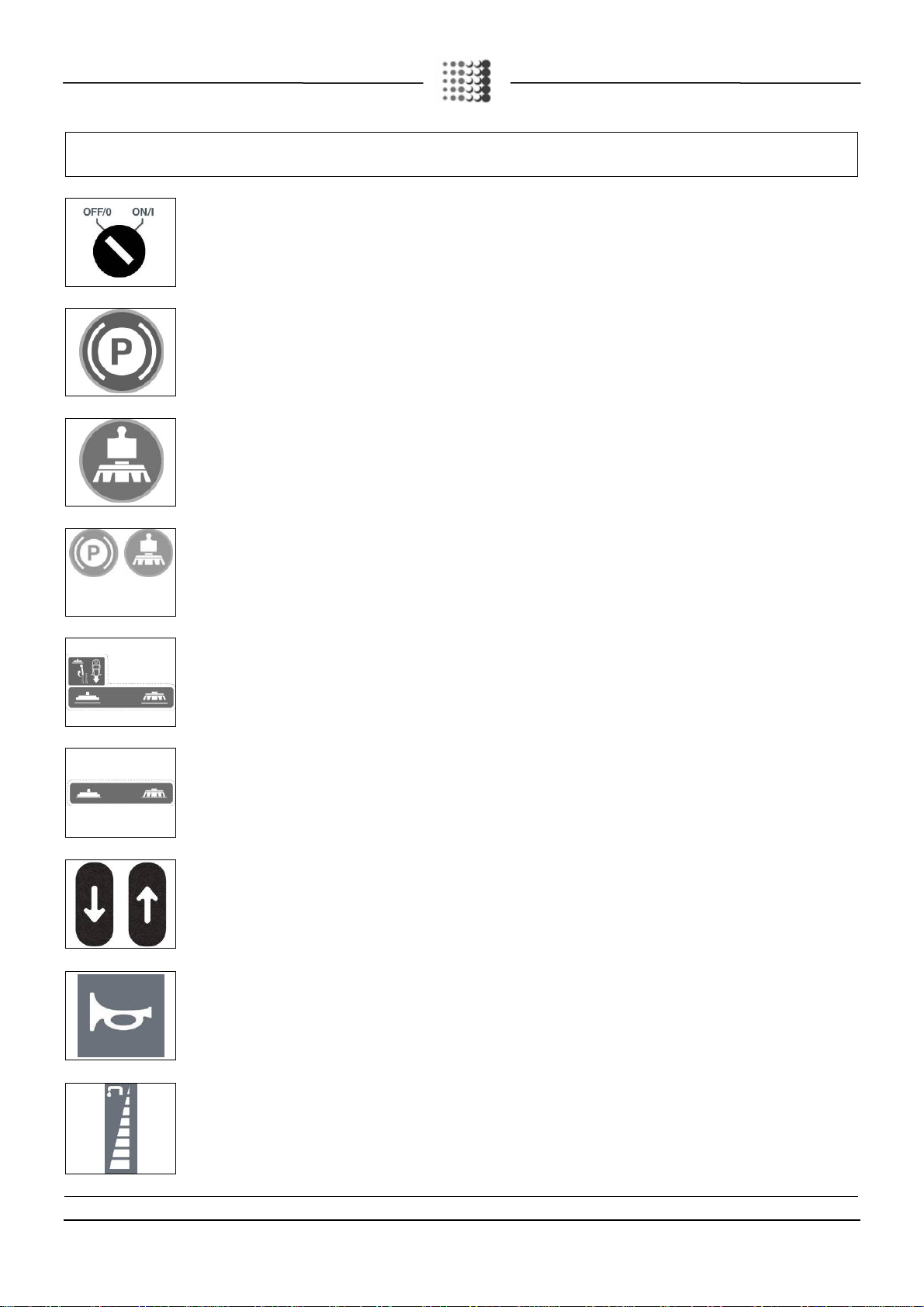
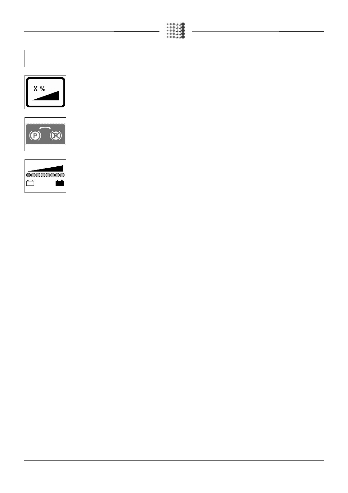
SYMBOLS USED ON THE MACHINE....................................................................................................................................7
GENERAL SAFETY REGULATIONS.....................................................................................................................................9
MACHINE PREPARATION................................................................................................................................................10
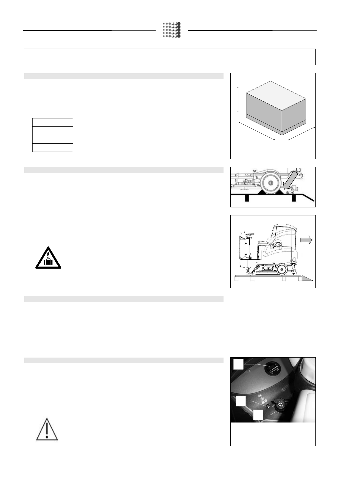
1. HANDLING OF THE PACKED MACHINE........................................................................................................................................10
2. HOW TO UNPACK THE MACHINE................................................................................................................................................10
3. HOW TO MOVE THE MACHINE ...................................................................................................................................................10
4. INSTRUMENT PANEL COMPONENTS ..........................................................................................................................................10
5. STEERING COLUMN COMPONENTS ...........................................................................................................................................11
6. FOOTBOARD FRONT-RIGHT COMPONENTS ................................................................................................................................11
7. FOOTBOARD FRONT-LEFT COMPONENTS ..................................................................................................................................11
8. FOOTBOARD REAR COMPONENTS ............................................................................................................................................11
9. MACHINE'S SIDE COMPONENTS ................................................................................................................................................12
10. MACHINE'S REAR COMPONENTS.............................................................................................................................................12
11. TYPE OF BATTERY.................................................................................................................................................................12
12. BATTERY MAINTENANCE AND DISPOSAL..................................................................................................................................12
13. FITTING THE BATTERIES INTO THE MACHINE............................................................................................................................13
14. BATTERY CONNECTION AND BATTERY CONNECTORS...............................................................................................................13
15. BATTERY CHARGER CONNECTION (VERSIONS WITHOUT BC).....................................................................................................14
16. BATTERY CHARGER CONNECTION (VERSIONS WITH CB) ...........................................................................................................15
17. BATTERY CHARGE LEVEL INDICATOR......................................................................................................................................16
18. WORKING FORWARD SPEED...................................................................................................................................................16
19. REVERSE FUNCTION..............................................................................................................................................................16
20. RECOVERY TANK...................................................................................................................................................................17
21. SOLUTION TANK....................................................................................................................................................................17
22. FILLING THE SOLUTION TANK..................................................................................................................................................17
23. DETERGENT SOLUTION..........................................................................................................................................................18
24. REGULATING THE DETERGENT...............................................................................................................................................18
25. ASSEMBLING THE SQUEEGEE.................................................................................................................................................18
26. SQUEEGEE INCLINATION........................................................................................................................................................19
27. ADJUSTING THE SQUEEGEE SUPPORT HEIGHT ........................................................................................................................19
28. BRUSH ASSEMBLY (MR60 B VERSIONS)....................................................................................................................................19
29. WASHING BRUSH HEAD CASING ASSEMBLY (MR 65-75-85-100 B VERSIONS)................................................................................19
30. DISC BRUSH ASSEMBLY (MR 65-75-85-100 B VERSIONS).............................................................................................................20
31. SERVICE BRAKE AND PARKING BRAKE ....................................................................................................................................20
32. BLINKING LIGHT (OPTIONAL)...................................................................................................................................................20
33. EMPTY SOLUTION TANK DEVICE..............................................................................................................................................21
34. WATER MANAGEMENT KIT (OPTIONAL) ....................................................................................................................................21
35. BASE EXTRA PRESSER (VERSIONS B)......................................................................................................................................21
WORK...........................................................................................................................................................................22
36. PREPARING TO WORK............................................................................................................................................................22
37. OVERFLOW DEVICE ...............................................................................................................................................................22
AT THE END OF THE WORK ............................................................................................................................................23
DAILY MAINTENANCE ....................................................................................................................................................24
38. CLEANING THE RECOVERY TANK............................................................................................................................................24
39. CLEANING THE SUCTION MOTOR FILTER .................................................................................................................................24
40. CLEANING THE SQUEEGEE.....................................................................................................................................................25
41. CLEANING THE SOLUTION TANK AND FILTER............................................................................................................................25
42. DISC BRUSH DISASSEMBLY (MR60 B VERSIONS).......................................................................................................................26
43. DISC BRUSH DISASSEMBLY (MR 65-75-85-100 B VERSIONS)........................................................................................................26

4
WEEKLY MAINTENANCE.................................................................................................................................................27
44. CLEANING THE SUCTION TUBE ...............................................................................................................................................27
EXTRAORDINARY MAINTENANCE ...................................................................................................................................28
45. REPLACING THE FRONT SQUEEGEE RUBBER...........................................................................................................................28
46. REPLACING THE REAR SQUEEGEE RUBBER.............................................................................................................................28
47. REPLACEMENT OF THE BRUSH HEAD CASING..........................................................................................................................28
TROUBLESHOOTING......................................................................................................................................................29
48. INSUFFICIENT WATER ON THE BRUSHES .................................................................................................................................29
49. THE SQUEEGEE DOES NOT DRY PERFECTLY ...........................................................................................................................29
50. THE MACHINE DOES NOT CLEAN WELL....................................................................................................................................29
51. EXCESSIVE FOAM PRODUCTION .............................................................................................................................................29
52. THE SUCTION MOTOR DOES NOT FUNCTION............................................................................................................................29
53. THE BRUSH MOTOR DOES NOT WORK.....................................................................................................................................30
54. THE MACHINE DOES NOT START.............................................................................................................................................30
55. ELECTRIC FUSES AND THERMAL CUT-OUTS.............................................................................................................................30
56. THE MACHINE DOES NOT REVERSE.........................................................................................................................................30
57. THE MACHINE DOES NOT MOVE FORWARD..............................................................................................................................30
DISPOSAL.....................................................................................................................................................................31
CHOOSING AND USING THE BRUSHES ............................................................................................................................32
EC DECLARATION OF CONFORMITY................................................................................................................................33

5
On consignment of the machine
When the machine is consigned to the customer, an immediate check
must be performed to ensure all the material mentioned in the shipping
documents has been received, and also to check the machine has not
suffered damage during transportation. If this is the case, the carrier
must ascertain the extent of the damage at once, informing our
customer service office. It is only by prompt action of this type that the
missing material can be obtained, and compensation for damage
successfully claimed.
Introductory comment
MR is a scrubbing machine that is able to clean a wide variety of types
of flooring and types of dirt by using the mechanical action of two disc or
cylindrical brushes, depending on the model, and the chemical action of
a water-detergent solution. As it advances, it also collects the dirt
removed and the detergent solution not absorbed by the floor.
The machine must be used only for this purpose. Even the best
machines will only work well if used correctly and kept in good working order.
We therefore suggest you to read this instruction booklet carefully and re-
read it whenever difficulties arise while using the machine. If necessary,
remember that our assistance service (organised in collaboration with our
dealers) is alwaysavailable foradvice ordirect intervention.
Intended use
The scrubbing machine is exclusively designed for the professional
cleaning of surfaces and floors in industrial, commercial and public
environments. The machine is only suitable for use in closed (or at least
covered) places.
The machine is not suitable for use in the rain, or under water jets. It is
FORBIDDEN to use the machine for picking up dangerous dusts or
inflammable liquids within places with a potentially explosive
atmosphere. In addition, it is not suitable as a means of transport for
people or objects.
Serial number plate

6
TECHNICAL DESCRIPTION UM MR60 B MR65 B MR75 B MR85 B MR100 B
Working width mm 610 650 750 850 1010
Squeegee width mm 780 970 970 1085 1085
Working capacity, up to m2/h 3660 3900 4500 5100 6000
Disk brush No. /
Ø mm
1 / 610 2 / 340 2 / 390 2 / 430 2 / 510
Brush rotations rpm. 170 170 170 170 120
Brush motor V/W 24 / 450 24 / 450 24 / 450 24 / 450 24 / 600
Pressure on the brushes kg 30 30 – 60 30 – 60 30 – 60 30
Traction motor V/W 24 / 400 24 / 400 24 / 400 24 / 400 24 / 400
Traction wheel Ø mm 220 220 220 220 220
Forward speed km/h 0¸6 0¸6 0¸6 0¸6 0¸6
Maximum gradient with full load % 10 10 10 10 10
Suction motor V/W 24 / 310 24 / 310 24 / 310 24 / 310 24 / 310
Suction vacuum mbar 160 160 160 160 160
Rear elastic wheels Ø mm 300x70 300x70 300x70 300x70 300x70
Solution tank l 110 110 110 110 110
Recovery tank l 125 125 125 125 125
Detergent tank (CDS version only) l -
5 5 5 5
Steering diameter mm 1910 1910 1910 1910 1910
Machine length mm 1495 1495 1495 1495 1495
Machine height mm 1320 1320 1320 1320 1320
Machine width (without squeegee) mm 680 680 680 680 1035
Battery compartment (l x L x h) mm 384x520x340
Rated battery voltage V 24 24 24 24 24
Battery weight (max) kg 136 136 136 136 136
Machine weight (empty and without batteries) kg 210 213 213 213 230
Machine weight in running order (machine + batteries +
water + operator) kg 530 535 535 535 555
Sound pressure level (ISO 11201) dB (A) - - - - -
Hand vibration level (ISO 5349) m/s2- - - - -
Body vibration level (ISO 2631) m/s2- - - - -

7
SYMBOLS USED ON THE MACHINE
Main switch symbol (key switch)
Used on the instrument panel, to indicate the key switch for machine operation on (I) or off (O)
Parking brake symbol
Used on the instrument panel to indicate the red warning light showing parking brake on
Symbol denoting pressure applied to the brushes
Used to indicate the green warning light that shows that the brush pressure increase has been engaged
Parking brake and brush pressure symbol
Used on the instrument panel to indicate the yellow warning light showing that the parking brake and pressure increase on the
brushes have been engaged
Brush head / squeegee motion symbol (idle position)
Used to indicate the movement levers of the brush head and squeegee
Brush head / squeegee motion symbol (working position)
Used to indicate the movement levers of the brush head and squeegee
Pedal labels that indicate the forward and reverse direction of the machine
Used to indicate the direction of the machine
Symbol denoting acoustic alarm
Used to indicate the acoustic alarm button
Water quantity adjustment symbol
Used on the steering column to indicate the knob for adjusting the quantity of water distributed on the brushes

8
SYMBOLS USED ON THE MACHINE
Indicates the maximum gradient
Parking brake symbol
Used on the machine to indicate the parking brake control lever
Symbol denoting battery electric charging

9
GENERAL SAFETY REGULATIONS
The regulations below must be carefully followed in order to avoid harm to the operator and damage to the machine.
Read the labels on the machine carefully. Do not cover them for any reason and replace them immediately if they become damaged.
The machine must be exclusively used by authorised, trained personnel.
The machine is designed for dry use only and should not be used or kept outdoors in wet conditions.
Disconnect from the mains/battery before performing cleaning or maintenance operations on the machine.
If the machine is used where there is a risk of falling objects, the machine must be equipped with protection devices against falling objects.
During the working of the machine, pay attention to other people and especially to children.
The machine is not suitable for cleaning carpets.
Do not mix different types of detergent as this may produce harmful gases.
Do not place any liquid containers on the machine.
The storage temperature must be between -25C and +55C; do not store outdoors in damp conditions.
Conditions of use: room temperature between 0°C and 40°C with relative humidity between 30 and 95%.
Do not use the machine in an explosive atmosphere.
Do not use the machine as a means of transport.
Do not use acid solutions that could damage the machine and/or harm people.
Do not vacuum inflammable liquids.
Do not use the device to collect dangerous powders.
In the event of a fire, use a powder extinguisher. Do not use water.
Do not knock against shelving or scaffolding, where there is a danger of falling objects. Use protective devices (helmet).
Adapt the speed to the adhesion conditions.
Do not use the machine on surfaces with an inclination greater than the one shown on the plate.
When the machine is in parking mode, remove the key and insert the parking brake.
If you notice any damage to the battery charger cable, contact a FIMAP technical assistance centre immediately.
The machine is designed to simultaneously carry out the washing and drying operations. Different operations should only be carried out in areas where
the passage of unauthorised persons is prohibited. Signal the presence of damp floors with suitable signs.
If the machine does not work properly, check this is not caused by failure to carry out routine maintenance. Otherwise, request the intervention of the
FIMAP technical assistance centre.
If you need to replace any components, request the ORIGINAL spare parts from a FIMAP dealer and/or Authorised Retailer.
Use original FIMAP brushes only indicated in the paragraph “CHOOSING AND USING THE BRUSHES".
In the event of danger, activate the emergency lever (connector placed under the operator's seat) immediately.
Before carrying out any maintenance work, switch off the machine and disconnect the battery connector.
Restore all electrical connections after any maintenance interventions.
Do not remove any protection devices which require the use of tools in order to be removed.
Do not wash the machine with direct water jets or with pressurised water, nor with corrosive substances.
Have the machine checked by a FIMAP assistance centre after at least every 200 hours of operation.
To prevent scaling in the solution tank filter, do not fill the tank with detergent solution many hours before using the machine.
Before using the machine, check that all the hatches and covers are positioned as shown in this Use and Maintenance Manual.
Make sure the recovery tank is empty before lifting.
When disposing of consumption materials, comply with currently effective laws and regulations.
The machine does not cause harmful vibrations.
When your FIMAP machine has reached the end of its long working life, dispose of the materials it contains (especially oils, batteries and electronic
components) in an appropriate manner, and bearing in mind that the machine itself was constructed using 100% recyclable materials.
The batteries must be removed from the machine before its disposal.
The batteries must be disposed of in a safe manner, fully observing the laws and regulations in force.
The machine is not suitable for use by children and persons with reduced physical, mental and sensory capabilities, or people who lack experience and
knowledge.
Children must be supervised to ensure they do not play with the device.
When the machine if left unattended, engage the parking brake for safety against unintentional movements.

10
MACHINE PREPARATION
1. HANDLING OF THE PACKED MACHINE
The machine is contained in specific packaging with a pallet for the handling with fork trucks. The
packages cannot be placed on top of each other.
The total mass of the machine with packaging is 240 kg (without batteries)
The dimensions of the packaging is as follows:
MR
A: 1610mm
B: 730mm
C: 1600mm
A
CB
2. HOW TO UNPACK THE MACHINE
1. Remove the outer packaging
2. The machine is fixed to the pallet with wedges which block the wheels
3. Remove the wedges
4. Use a chute to get the machine down from the pallet, pushing it backwards. Do not assemble the rear
squeegee before unloading the machine, and avoid violently jolting the brush head. To assemble the
squeegee, read the “ASSEMBLING THE SQUEEGEE” paragraph.
5. Keep the pallet for any future transport needs
WARNING: if the product is delivered in cardboard containers, handle the
packed product with suitable lifting means that comply with the legal
requirements
3. HOW TO MOVE THE MACHINE
1. Make sure the recovery tank and the solution tank are empty
2. Check that the base and squeegee are lifted off the ground
3. Place it on a pallet using a chute
4. Check that the key switch is on OFF and remove the key
5. Engage the parking brake
6. Secure the machine to the pallet using wooden wedges
4. INSTRUMENT PANEL COMPONENTS
The instrument panel components are identified as follows:
1) Battery level / hour-counter display
2) Main key switch
3) Indicator light that can light up with:
Red: Parking brake engaged
Green: increase of pressure on the brush head unit engaged
Yellow: parking brake and increased pressure on the brush head unit engaged
WARNING: If you try to leave with the parking brake engaged and the pedal for
increasing pressure on the brush head engaged, the machine will not move and a
yellow indicator light on the instrument panel will come on, disengage both to move off.
1
3
2

11
MACHINE PREPARATION
5. STEERING COLUMN COMPONENTS
The steering column components are identified as follows:
4) Squeegee body lifting lever
5) Brush head body lifting lever
6) Horn button
7) Detergent solution adjustment lever
6. FOOTBOARD FRONT-RIGHT COMPONENTS
The components at the front right of the footboard are identified as follows:
8) Accelerator pedal, forward
9) Accelerator pedal, reverse
WARNING: Only by simultaneously pressing the pedals is the reverse made
7. FOOTBOARD FRONT-LEFT COMPONENTS
The components at the front left of the footboard are identified as follows:
10) Brake pedal
11) Parking brake lever
8. FOOTBOARD REAR COMPONENTS
The components at the rear of the footboard are identified as follows:
12) Detergent solution level tube
13) Base extra pressure pedal (see paragraph BASE EXTRA-PRESSURE)
7
6
5
4
9
8
10 11
12
13

12
MACHINE PREPARATION
9. MACHINE'S SIDE COMPONENTS
The side components of the machine are identified as follows:
14) Water-detergent filler cap
15) Water filler cap
16) Water-detergent drainage cap
10. MACHINE'S REAR COMPONENTS
The rear components of the machine are identified as follows:
17) Recovery tank discharge cap
11. TYPE OF BATTER
Y
To power the machine it is necessary to use:
liquidelectrolyte lead traction batteries;
sealed traction batteries with gas recombination or gel technology.
OTHER TYPES MUST NOT BE USED.
The batteries must meet the requirements laid out in the norms: CEI EN 60254-1:2005-12 (CEI 21-5) +
CEI EN 60254-2:2008-06 (CEI 21-7)
The battery compartment can house four 6V or two 12V batteries
For a good operating performance, we suggest the use of four 6V/210 Ah C5 batteries
12. BATTERY MAINTENANCE AND DISPOSAL
For maintenance and recharging, comply with the instructions provided by the battery manufacturer.
Particular attention must be paid when choosing the battery charger, if not supplied, since there are
different kinds according to the type and capacity of the battery.
When the battery reaches the end of its working life, it must be disconnected by expert, trained personnel,
then lifted (using the grips and suitable lifting devices) to remove it from the battery compartment. DEAD
BATTERIES ARE CLASSIFIED AS DANGEROUS WASTE AND MUST BE DELIVERED TO THE
AUTHORISED BODIES FOR CORRECT DISPOSAL.
16
14
15
17

13
MACHINE PREPARATION
WARNING: You are advised to always wear protective gloves, to avoid the risk
of serious injury to your hands.
WARNING: You are advised to only lift and move the batteries with lifting and
transportation means suitable for the specific weight and size
13. FITTING THE BATTERIES INTO THE MACHINE
The batteries must be housed in the special compartment beneath the recovery tank. They should be
handled using lifting equipment that is suitable in terms of both weight and hook-up system. They must
also satisfy the requirements of Standard CEI 21-5. The dimensions of the battery compartment are: 384 x
520 x H340 mm.
WARNING: For battery maintenance and daily recharging, you must fully respect
the indications provided by the manufacturer or retailer. All installation and
maintenance operations must be carried out by specialised personnel.
To insert the batteries you must:
1. Lock the machine engaging the brake lever
2. Make sure that the key switch is in the “OFF” position
3. Make sure the recovery tank is empty, otherwise empty it completely
4. Grip the handle under the seat to open the recovery tank
5. Lift the recovery tank until it hooks to the end of the safety clamp
6. house the batteries in the compartment, positioning the poles “+” and “-“ opposite each other
WARNING: you are advised to use airtight batteries only, to avoid the leakage
of acids!
ATTENTION: you are advised to always wear protective gloves, to avoid the
risk of serious injury to your hands.
ATTENTION: You are advised to only lift and move the batteries with lifting
and transportation means suitable for the specific weight and size
14. BATTERY CONNECTION AND BATTERY CONNECTORS
1. connect the batteries in series - using the jumper cables supplied (3) - to the poles “+” and “-“
2. Connect the battery connector cable (1) to the terminal poles “+” and “-“ to obtain a voltage of 24V on
the clamps
3. Connect the battery connector (1) to the machine connector (2).
3
1 2

14
MACHINE PREPARATION
WARNING: you are advised to have the electric connections made by a
qualified, FIMAP trained technician
WARNING: you are advised to always wear protective gloves in order to avoid
the risk of serious injury to your hands.
15. BATTERY CHARGER CONNECTION (VERSIONS WITHOUT BC)
In order not to cause permanent damage to the batteries it is essential to avoid their complete discharge:
arrange the recharge within a few minutes of the switching on of the flashing "discharged batteries" signal.
ATTENTION: never leave the batteries completely discharged, even if the
machine is not being used. Check the battery charger is suitable for the
batteries installed, in terms of both capacity and type.
To connect the batteries you must:
1. Make sure the recovery tank is empty, otherwise empty it completely
2. Move the machine near to the battery charger
3. Engage the parking brake
4. Put the key switch to the “OFF” position
5. Grip the handle under the seat to open the recovery tank
6. Lift the recovery tank until it hooks to the end of the safety clamp
7. Disconnect the electrical connector from the battery connector (1) from the machine connector (2)
8. Connect the battery charger cable connector
9. Close the recovery tank until the prop is hooked in the first point of the safety stop
The coupling connector of the battery charger is consigned inside the bag containing this instruction
booklet, and must be assembled on the cables of the battery charger as indicated in the instructions.
ATTENTION: this process must be carried out by qualified personnel. An
incorrect connection of the connector may cause problems with machine
functioning.
10. Connect the recently wired cable to the external battery charger
ATTENTION: Carefully read the use and maintenance instructions of the
battery charger that is used for charging.
ATTENTION: Keep the recovery tank open for the duration of the battery
recharging cycle to allow gas fumes to escape
11. After recharging the batteries completely, the battery connector (1) must be connected to the
machine connector (2)
3

15
MACHINE PREPARATION
ATTENTION: danger of exhalation of gas and leakage of corrosive liquids.
ATTENTION: danger of fire: do not go near with free flames
16. BATTERY CHARGER CONNECTION (VERSIONS WITH CB)
In order not to cause permanent damage to the batteries it is essential to avoid their complete discharge:
arrange the recharge within a few minutes of the switching on of the flashing "discharged batteries" signal.
ATTENTION: never leave the batteries completely discharged, even if the
machine is not being used. Check the battery charger is suitable for the
batteries installed, in terms of both capacity and type.
To connect the batteries you must:
1. Make sure the recovery tank is empty, otherwise empty it completely
2. Move the machine near to the battery charger
3. Engage the parking brake
4. Put the key switch to the “OFF” position
5. Grip the handle under the seat to open the recovery tank
6. Lift the recovery tank until it hooks to the end of the safety clamp
7. Connect the battery charger cable to the socket (1) on the charger itself
8. Close the recovery tank until the prop is hooked in the first point of the safety stop
9. Plug the battery charger cable into the mains socket.
The charger power cable is delivered inside the bag containing this instruction booklet.
ATTENTION: this process must be carried out by qualified personnel. An
incorrect connection of the connector may cause problems with machine
functioning.
WARNING: Carefully read the use and maintenance manual of the charger
that is delivered inside the bag containing this instruction booklet.
WARNING: Before inserting the charger power cable into the socket, verify
that there is no condensate or other forms of liquids.
1

16
MACHINE PREPARATION
ATTENTION: the machine is equipped with an automatic system that
disconnects the power supply from the electrical system while the batteries are
being recharged
ATTENTION: in order not to cause permanent damage to the batteries it is
essential to avoid their complete discharge: arrange the recharge within a few
minutes of the switching on of the flashing "discharged batteries" signal.
ATTENTION: never leave the batteries completely discharged, even if the
machine is not being used.
ATTENTION: for the daily recharging of the batteries, you must fully respect
the indications provided by the manufacturer or retailer. All installation and
maintenance operations must be carried out by specialised personnel.
ATTENTION: Always make sure the green LED of the battery charger is on
before using the machine again
ATTENTION: danger of exhalation of gas and leakage of corrosive liquids.
ATTENTION: danger of fire: do not go near with free flames
17. BATTERY CHARGE LEVEL INDICATO
R
The battery indicator uses LEDs and has 8 positions (7 yellow - charged batteries, and 1 red - run down
batteries).
WARNING: A few seconds after the red indicator light comes on, the brush
motor switches off automatically. With the remaining charge it is still possible,
however, to complete the drying process before recharging
18. WORKING FORWARD SPEED
This machine is equipped with electronic traction control.
To move the machine, after having turned the key in the ON position, push the drive pedal (6) adjusting
the speed by pressing and releasing the pedal. The machine will then start moving.
19. REVERSE FUNCTION
To make a reversing manoeuvre, press both pedals (6 and 7) the machine will then start moving
backwards. During reverse motion, the machine emits an acoustic signal.
6
7

17
MACHINE PREPARATION
20. RECOVERY TANK
Make sure the recovery tank is empty, otherwise empty it completely.
Check the cap of the drainage tube (10) (on the rear of the machine) is correctly closed.
21. SOLUTION TANK
The recovery tank must be completely empty each time the solution tank is filled.
Remove the front inlet cap and check the solution filter is correctly fitted.
Check that thesolution filtercap (1), underthe solution tank inthe front right of themachine, is properlyclosed.
22. FILLING THE SOLUTION TANK
The solution tank can be filled in three different ways:
1. Unscrew the filler cap (1) and fill using a hose.
2. Using the rubber cap (2), this supports the water hose on its own, be sure to unscrew the cap to allow
the proper vent of air.
3. Using on request (optional) a tank clean water refilling system via a quick coupling (3), FFF with float
to control the overflow.
1
1
2
3

18
MACHINE PREPARATION
23. DETERGENT SOLUTION
Remove the filler cap (1) and check the solution filter is correctly assembled.
Check that the filter cap, under the solution tank in the front right of the machine, is properly closed.
Fill it with clean water at a temperature not exceeding 50C. The amount inside the tank can be seen by
means of the level pipe on the front left of the seat. The solution tank has a maximum capacity of about
110 litres. Add the liquid detergent to the tank in the concentration and manner indicated on the detergent
manufacturer's label. The formation of excess foam could damage the suction motor, so use only the
minimum amount of detergent that is necessary.
WARNING: Always use detergents whose manufacturer's label indicates their
suitability for scrubbing machines. Do not use acid or alkaline products or
solvents without this indication.
ATTENTION: Protective gloves should always be worn before handling
detergents or acidic or alkaline solutions to avoid serious injury to hands.
ATTENTION: always use low foam detergent. To avoid the production of
foam, before starting to clean, put a minimum quantity of antifoam liquid into
the recovery tank. Do not use pure acids.
24. REGULATING THE DETERGENT
Firstly, fully open the outflow of the tap, by means of the lever (3) on the steering column. During the first
few meters, check that the amount of solution to wet the floor is sufficient, but not too much that it exits the
splash-guard, the adjustment of the detergent application is made by means of lever (3) (shifting it
downwards increases the flow, shifting it upwards decreases it). Bear in mind that the correct amount of
solution is always depends on the nature of the floor, the degree of dirt and the forward speed.
25. ASSEMBLING THE SQUEEGEE
For packaging reasons, the squeegee is supplied disassembled from the machine, and must be
assembled as shown in the figure.
Raise the squeegee connection by means of the left lever (1) turning it clockwise into the vertical position.
Make sure the parking brake is engaged and that the main switch is OFF. First thread left pin (2) of the
squeegee into the left slot on the arm and then right pin (3) into the right slot, being careful to keep the
spring and the washer above the arm’s flat bar. This can be simplified by first loosening the handwheel on
the pin. Then re-tighten the handwheel to block the squeegee in place.
Insert the squeegee tube in the appropriate sleeve (4).
1

19
MACHINE PREPARATION
26. SQUEEGEE INCLINATION
During working operation, the rear rubber is slightly tilted backwards (by about 5mm) in a uniform way for
its whole length.
If it is necessary to increase the bend of the rubber in the central part, you must tilt the squeegee
backwards, rotating the adjuster screw (1) clockwise.
27. ADJUSTING THE SQUEEGEE SUPPORT HEIGHT
The height of the squeegee must be adjusted on the basis of the state of wear and tear of the rubber.
Carry out the following operations for adjustment:
1. unscrew the locking nut
2. raise or lower the wheels (1) by sliding them on the slot of the support
3. block it by tightening the locking nut once the required height is reached.
NB: to facilitate the operation, completely lower the squeegee and put a spacer of a few millimetres (2 to 4 mm
dependingon thetype of rubber) under the wheel.
28. BRUSH ASSEMBLY (MR60 B VERSIONS)
1. Make sure the parking brake is engaged and that the main switch is OFF
2. Raise the brush head by turning the righthand lever (1) for the counter-clockwise movement of the
brush head.
WARNING: during this operation, verify that there are no people or objects
near the brush.
3. With the brush head in a high position put the brushes in the housing of the plate under the brush
head, turning them until the three buttons go into the niches of the plate itself; turn the brush
clockwise until the pin is pushed towards the coupling spring and is locked into place.
WARNING: You are advised to always wear protective gloves, to avoid the risk
of serious injury to your hands.
29. WASHING BRUSH HEAD CASING ASSEMBLY (MR 65-75-85-100 B VERSIONS)
Make sure the parking brake is engaged and that the main switch is OFF. Raise the brush head by turning
the righthand lever for the counter-clockwise movement of the brush head. The casing of the washing base
that for reasons of packaging are supplied disassembled from the machine, must be mounted as shown.

20
MACHINE PREPARATION
30. DISC BRUSH ASSEMBLY (MR 65-75-85-100 B VERSIONS)
1. Make sure the parking brake is engaged and that the main switch is OFF
2. Raise the brush head by turning the righthand lever (1) for the counter-clockwise movement of the
brush head.
WARNING: During this operation, check there are no people or objects near
the brush.
3. With the base up, insert the brushes in the plate housing beneath the base, turning them until the
three pins enter the niches in the plate itself; turn until the pin is pushed towards the coupling spring
and is locked into place. The photo shows the rotation direction to hook up the right-hand brush; for
the left-hand one, rotate in the opposite direction.
ATTENTION: You are advised to always wear protective gloves, to avoid the risk
of serious injury to your hands.
You are advised to invert the right and left-hand brushes every day. If the brushes are not new however,
and have deformed bristles, it is better to reassemble them in the same position (the right-hand one on the
right, and the left-hand one on the left), to prevent the different inclination of the bristles producing an
overload on the brush motor as well as excessive vibrations.
31. SERVICE BRAKE AND PARKING BRAKE
The machine has an electronic braking system. To brake, in normal conditions, just remove your foot from
the accelerator pedal. If this service brake is working badly, or if necessary, activate the brake pedal (13)
pushing it downwards. To engage the parking brake, press the brake pedal (13) and lock it by pulling the
lever (14) to the left. The red indicator light on the instrument panel will switch on.
WARNING: If you try to leave with the parking brake on, the machine will not move;
always disengage the parking brake before starting to work or moving
32. BLINKING LIGHT (OPTIONAL)
The machine can be equipped with a blinking light that turns on automatically when the key in the main
switch is turned on.
This manual suits for next models
5
Table of contents
Other CONQUEST Scrubber manuals
Popular Scrubber manuals by other brands

Lincoln Electric
Lincoln Electric PRISM CIRCULATOR 4000 Operator's manual

Nautilus
Nautilus HYDRO-FORCE MX200M operating manual

Tennant
Tennant 5400 Operator and parts manual

Fox
Fox F50-843 Assembly and operating instructions

HAKO
HAKO Scrubmaster B260 R Service booklet

Lavorwash
Lavorwash Clean Track NANOscrub Evo 50 cbt instructions

Xtreme Polishing Systems
Xtreme Polishing Systems Genie Magic 2 manual

Kärcher
Kärcher BD 43/40 C Ep manual

Parkside
Parkside 291645 Translation of the original instructions

Black & Decker
Black & Decker SB450 ScumBuster instruction manual

Nelson-Jameson
Nelson-Jameson Clean Logix BLX-600 user manual

CDA
CDA CCA51 Installation, use and maintenance