CONQUEST MY530B User manual

CONQUEST
MY530BFLOOR SCRUBBER
OPERATOR MANUAL
T: 1800 826 789
E: support@conquestequipment.com.au
W: conquestequipment.com.au
FIMY530-OM-V01

The descriptions contained in this document are not binding.
The company therefore reserves the right to make any modifications at any time to elements,
details, or accessory supply, as considered necessary for reasons of improvement or
manufacturing/commercial requirements.
The reproduction, even partial, of the text and drawings contained in this document is prohibited
by law.
The company reserves the right to make any technical and/or supply modifications. The images
are for reference purposes only, and are not binding in terms of design and supply.
Symbols used in the manual
Open book symbol with an "i"
Indicates the need to consult the instruction manual
Open book symbol
Used to tell the operator to read the manual before using the machine
Warning symbol
Carefully read the sections marked with this symbol and comply with the
specifications for the safety of the operator and the machine
Disposal symbol:
Carefully read the sections marked with this symbol for disposal of the
machine or parts of it
Warning symbol
Indicates danger of gas exhalation and leakage of corrosive liquids
Warning symbol
Indicates the danger of fire
Do not go near with free flames
Warning symbol
Indicates that the packed product should be handled with suitable lifting
means that comply with the legal requirements

3
CONTENTS
ON CONSIGNMENT OF THE MACHINE..........................................................................................................................................................................................................................4
SERIAL NUMBER PLATE.................................................................................................................................................................................................................................................4
INTRODUCTION..............................................................................................................................................................................................................................................................4
INTENDED USE........................................................................................................................................................................................ERRORE. IL SEGNALIBRO NON È DEFINITO.
TECHNICAL DESCRIPTION ............................................................................................................................................................................................................................................5
GENERAL SAFETY REGULATIONS................................................................................................................................................................................................................................8
MACHINE PREPARATION...............................................................................................................................................................................................................................................9
1. INTENDED USE....................................................................................................................................................................................................................................................................9
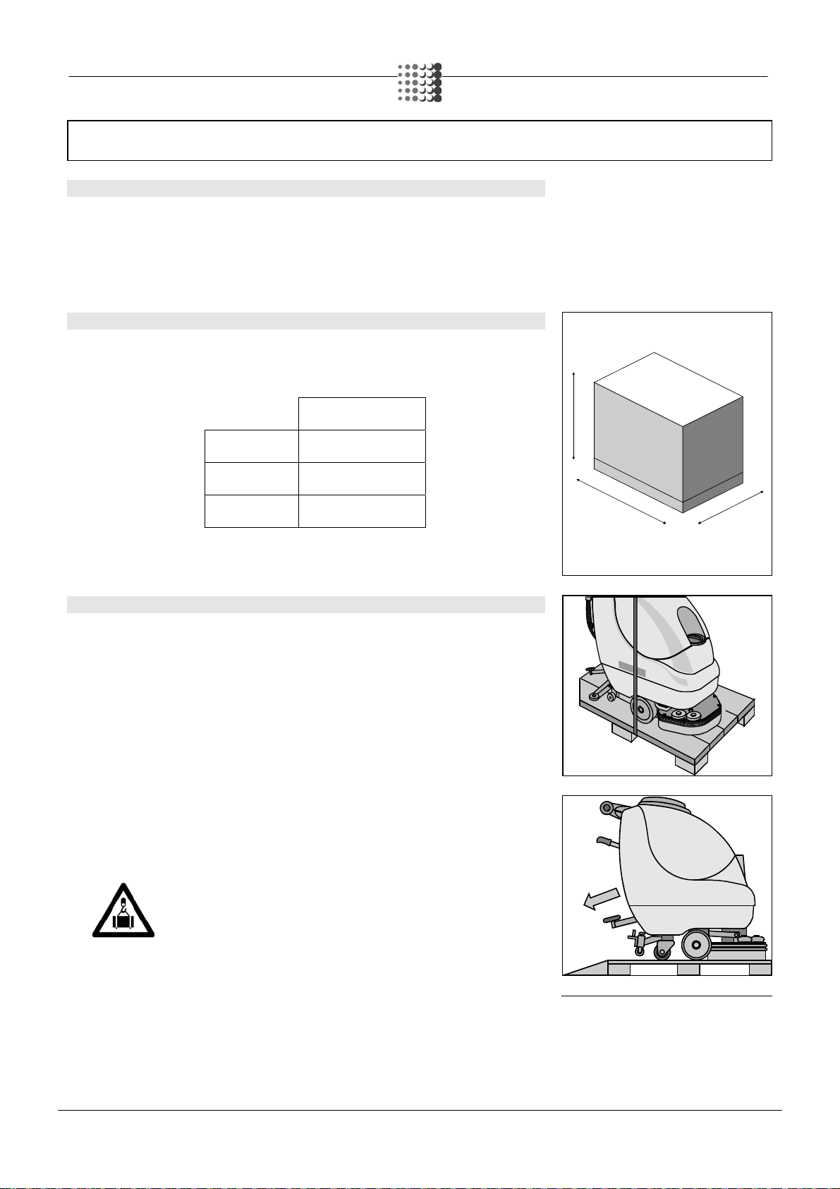
2. HANDLING THE PACKAGED MACHINE..............................................................................................................................................................................................................................9
3. HOW TO UNPACK THE MACHINE......................................................................................................................................................................................................................................9
MACHINE PREPARATION.............................................................................................................................................................................................................................................10
4. HOW TO MOVE THE MACHINE.........................................................................................................................................................................................................................................10
5. TYPE OF BATTERY (FOR B SYSTEM ONLY)................................................................................................................................................................................................................... 10
6. BATTERY MAINTENANCE AND DISPOSAL (FOR B SYSTEM ONLY)..............................................................................................................................................................................10
MACHINE PREPARATION.............................................................................................................................................................................................................................................11
7. FITTING/CONNECTION OF THE BATTERY (FOR SYSTEM B ONLY)..............................................................................................................................................................................11
MACHINE PREPARATION.............................................................................................................................................................................................................................................12
8. BATTERY CHARGER (FOR SYSTEM B ONLY).................................................................................................................................................................................................................12
MACHINE PREPARATION.............................................................................................................................................................................................................................................13
9. CONNECTION OF THE ELECTRICAL POWER SUPPLY CONNECTOR (FOR SYSTEM B ONLY).................................................................................................................................13
10. CHARGING THE BATTERY WITH BUILT-IN BATTERY CHARGER (OPTIONAL SYSTEM B ).......................................................................................................................................13
MACHINE PREPARATION.............................................................................................................................................................................................................................................14
11. BATTERY CHARGE LEVEL INDICATOR (SYSTEM B)....................................................................................................................................................................................................14
MACHINE PREPARATION.............................................................................................................................................................................................................................................15
12. HOUR COUNTER INDICATOR (OPTIONAL SYSTEM B).................................................................................................................................................................................................15
13. SOLENOID VALVE CONTROL SWITCH (OPTIONAL SYSTEM E).................................................................................................................................................................................. 15
14. INSTRUMENT PANEL COMPONENTS............................................................................................................................................................................................................................ 15
15. REAR COMPONENTS......................................................................................................................................................................................................................................................15
16. FRONT COMPONENTS....................................................................................................................................................................................................................................................16
17. ASSEMBLING THE SQUEEGEE...................................................................................................................................................................................................................................... 16
18. ADJUSTING THE SQUEEGEE INCLINATION..................................................................................................................................................................................................................16
MACHINE PREPARATION.............................................................................................................................................................................................................................................17
19. ADJUSTING THE SQUEEGEE HEIGHT...........................................................................................................................................................................................................................17
20. RECOVERY TANK............................................................................................................................................................................................................................................................ 17
MACHINE PREPARATION.............................................................................................................................................................................................................................................18
21. SOLUTION TANK / DETERGENT SOLUTION.................................................................................................................................................................................................................. 18
22. BASE SPLASH GUARD RUBBER ASSEMBLY (SINGLE BRUSH VERSION)................................................................................................................................................................. 18
MACHINE PREPARATION.............................................................................................................................................................................................................................................19
23. BASE SPLASH GUARD RUBBER ASSEMBLY (DUAL BRUSH VERSION)..................................................................................................................................................................... 19
24. BRUSH ASSEMBLY (SINGLE BRUSH VERSION).......................................................................................................................................................................................................... 19
25. BRUSH ASSEMBLY (DUAL BRUSH VERSION)..............................................................................................................................................................................................................20
26. REGULATING THE SOLUTION........................................................................................................................................................................................................................................20
MACHINE PREPARATION.............................................................................................................................................................................................................................................21
WORK............................................................................................................................................................................................................................................................................22
1.PREPARATION FOR WORK (SYSTEM B)..........................................................................................................................................................................................................................22
WORK............................................................................................................................................................................................................................................................................23
2.PREPARATION FOR WORK (SYSTEM E)..........................................................................................................................................................................................................................23
WORK............................................................................................................................................................................................................................................................................24
2. FORWARD MOVEMENTS..................................................................................................................................................................................................................................................24
3. OVERFLOW DEVICE..........................................................................................................................................................................................................................................................24
AT THE END OF THE WORK.........................................................................................................................................................................................................................................25
1. AT THE END OF THE WORK.............................................................................................................................................................................................................................................25
DAILY MAINTENANCE...................................................................................................................................................................................................................................................26
1. CLEANING THE RECOVERY TANK...................................................................................................................................................................................................................................26
2. CLEANING THE SUCTION FILTER....................................................................................................................................................................................................................................26
3. DISASSEMBLING AND CLEANING THE SQUEEGEE.......................................................................................................................................................................................................27
4. DISASSEMBLING THE BRUSH (SINGLE BRUSH BASE).................................................................................................................................................................................................. 27
4. DISASSEMBLING THE BRUSH (DUAL BRUSH BASE))....................................................................................................................................................................................................28
5. CLEANING OF THE SOLUTION DISCHARGE FILTER......................................................................................................................................................................................................28
WEEKLY MAINTENANCE..............................................................................................................................................................................................................................................29
1.CLEANING THE SQUEEGEE TUBE....................................................................................................................................................................................................................................29
2. CLEANING THE SOLUTION TANK ....................................................................................................................................................................................................................................29
3. REPLACING THE SQUEEGEE RUBBERS.........................................................................................................................................................................................................................30
TROUBLESHOOTING....................................................................................................................................................................................................................................................31
1. INSUFFICIENT WATER ON THEBRUSH..........................................................................................................................................................................................................................31
2. THE MACHINE DOES NOT CLEAN WELL......................................................................................................................................................................................................................... 31
3. THE SQUEEGEE DOES NOT DRY PERFECTLY...............................................................................................................................................................................................................31
4. EXCESSIVE FOAM PRODUCTION....................................................................................................................................................................................................................................31
6. ELECTRICAL FUSES AND THERMAL PROTECTIONS (SYSTEM E)...............................................................................................................................................................................31
DISPOSAL......................................................................................................................................................................................................................................................................32
CHOOSING AND USING THE BRUSHES......................................................................................................................................................................................................................33
EC DECLARATION OF CONFORMITY..........................................................................................................................................................................................................................34
EC DECLARATION OF CONFORMITY..........................................................................................................................................................................................................................35

4
On consignment of the machine
When the machine is delivered to the customer, an immediate check must
be performed to ensure all the material mentioned in the shipping
documents has been received, and also to check the machine has not
been damaged during transportation. If this is the case, the carrier must
ascertain the extent of the damage at once, informing our customer
service office. It is only by prompt action of this type that the missing
material can be obtained, and compensation for damage successfully
claimed.
Introduction
Minny is a floor scrubbing machine which, via the mechanical action of the
rotating brush and the chemical action of a water/detergent solution, can
clean any type of flooring. As it advances, it also collects the dirt removed
and the detergent solution not absorbed by the floor.
The machine must only be used for this purpose. Even the best
machines will only work well if used correctly and kept in good working
order. We therefore suggest you read this instruction booklet carefully and
read it again whenever difficulties arise while using the machine. If
necessary, remember that our customer assistance service (organised in
collaboration with our dealers) is always available for advice or direct
intervention.
Serial number plate

5
TECHNICAL DESCRIPTION UM Minny 420B Minny 430B Minny 520B Minny 530B
Rated power W 770 770 770 770
Power supply voltage V 24 24 24 24
Frequency Hz - - - -
Working width mm 420 430 510 510
Width of rear squeegee mm 660 660 660 755
Work capacity m2/h 1200 1350 1350 1750
Brush diameter ∅mm 210 (x2) 420 (x1) 255 (x2) 510 (x1)
Brush rotations rpm 340 140 275 140
Pressure on the brushes kg 20 20 22 20
Brush motor V / W 24/400 24/400 24/400 24/400
Forward speed type Semi-aut. Semi-aut. Semi-aut. Semi-aut.
Maximum gradient % 2% 2% 2% 2%
Forward speed km/h 3.5 3.5 3.5 3.5
Suction motor W 370 370 370 370
Suction vacuum mbar 100 100 100 100
Traction motor V / W - - - -
Solution tank PE l 36 36 36 36
Recovery tank PE l 40 40 40 40
Gross weight of the machine ready for use kg 112 112 115 115
Batteries V / AhC5 24/50 - 70 24/50 - 70 24/50 - 70 24/50 – 70
Battery weight kg 42 42 42 42
Battery compartment dimensions (Length / Height / Width) mm / mm / mm 360x330x250
Machine dimensions (Length / Height / Width) mm / mm / mm 1060x960x455 1060x960x455 1060x960x565 1060x960x555
Noise level (in compliance with IEC 704/1) dB (A) 67 67 67 67
Vibration level m/s21.00 1.00 1.00 1.00
TECHNICAL DESCRIPTION UM Minny 430E Minny 500E Minny 530E
Rated power W 900 1200 900
Power supply voltage V 230 230 230
Frequency Hz 50 50 50
Working width mm 420 510 500
Width of rear squeegee mm 660 660 660
Work capacity m2/h 1200 1350 1350
Brush diameter ∅mm 420 (x1) 510 (x1) 510 (x1)
Brush rotations rpm 140 240 140
Pressure on the brushes kg 20 20 20
Brush motor V / W 230/450 230/750 230/450
Type of advance Semi-aut. Semi-aut. Semi-aut.
Maximum gradient % 2% 2% 2%
Forward speed km/h 3.5 3.5 3.5
Suction motor W 450 450 450
Suction vacuum mbar 100 100 100
Traction motor V / W - - -
Solution tank PE l 36 36 36
Recovery tank PE l 40 40 40
Gross weight of the machine ready for use kg 112 115 115
Batteries V / AhC5 - - -
Battery weight kg - - -
Battery compartment dimensions (Length / Height / Width) mm / mm / mm - - -
Machine dimensions (Length / Height / Width) mm / mm / mm 1060x960x455 1060x960x555 1060x960x555
Noise level (in compliance with IEC 704/1) dB (A) 67 67 67
Vibration level m/s21.00 1.00 1.00

6
SYMBOLS USED ON THE MACHINE
Solution tap symbol.
Used on the control panel to indicate that the solution tap is open (version B).
Suction motor symbol.
Used on the control panel to indicate the suction motor switch.
Brush motor symbol.
Used on the control panel to indicate the brush motor switch - master switch.
Battery charge level indicator
Also indicates the position of the tap (off = tap closed, on = tap open)
Base raise-lower symbol.
Used on the rear casing to indicate the base raise-lower lever.
Indicates the maximum gradient
Squeegee raise-lower symbol.
Used on the rear casing to indicate the squeegee raise-lower lever.
Indicates the maximum temperature of the detergent solution
Located near the solution tank inlet
Indicates the recovery tank drainage tube

7
SYMBOLS USED ON THE MACHINE
Indicates that there are electrical components nearby that can accumulate residual voltage (E version only)
Represents the voltage indicator light (version E).
Solution tap symbol. Used on the control panel to indicate that the solution tap is open (version E).
Indicates the control switch in versions with solenoid valve (optional)
Indicates the machines electrical earthing point (E version only)

8
GENERAL SAFETY REGULATIONS
The regulations below must be carefully followed in order to avoid harm to the operator and damage to the machine.
•Read the labels on the machine carefully. Do not cover them for any reason and replace them immediately if they become damaged.
•The machine must be exclusively used by authorised, trained personnel.
•During the working of the machine, pay attention to other people and especially to children.
•The machine is not suitable for cleaning carpets.
•The socket for the battery charger cable must have a prescribed earth connection.
•Avoid damaging the battery charger cable by crushing or bending it, or by applying stress.
•Do not let the power cable come into contact with the rotating brush.
•If the power supply cable is damaged, do not use the machine and contact a FIMAP service centre immediately.
•If you notice any damage to the battery charger cable, contact a FIMAP technical assistance centre immediately.
•Do not mix different types of detergent as this may produce harmful gases.
•Do not place any liquid containers on the machine.
•The machine is designed for dry use only and should not be used or kept outdoors in damp conditions.
•The storage temperature must be between -25°C and +55°C; do not store outdoors in damp conditions.
•Conditions of use: room temperature between 0°C and 40°C with relative humidity between 30 and 95%.
•Do not use the machine in an explosive atmosphere.
•Do not use the machine as a means of transport.
•Do not use acid solutions which may damage the machine.
•Avoid working with the brushes when the machine is standing still, so as not to damage the floor.
•Do not vacuum inflammable liquids.
•Do not use the device to collect dangerous powders.
•In the event of a fire, use a powder extinguisher. Do not use water.
•Do not knock against shelving or scaffolding, where there is a danger of falling objects.
•If you use the machine where there is a risk of falling objects, the machine must be equipped with protection devices against falling objects.
•Do not use the machine on surfaces with an inclination greater than the one shown on the plate.
•The machine is designed to simultaneously carry out the washing and drying operations. Different operations should only be carried out in
areas where the passage of unauthorised persons is prohibited. Signal the presence of damp floors with suitable signs.
•If the machine does not work properly, verify that this is not caused by failure to carry out routine maintenance. Otherwise, request the
intervention of the FIMAP technical assistance centre.
•If you need to replace any components, request the ORIGINAL spare parts from a FIMAP dealer and/or Authorised Retailer.
•For all maintenance interventions, switch off the machine and disconnect the battery connector or the power supply cable.
•Do not remove any protection devices which require the use of tools in order to be removed.
•Do not wash the machine with direct water jets or with pressurised water, nor with corrosive substances.
•Send the machine to a FIMAP technical assistance centre for servicing at least once a year.
•To prevent scaling in the solution tank filter, do not fill the tank with detergent solution many hours before using the machine.
•Before using the machine, check that all the hatches and covers are positioned as shown in this Manual.
•When disposing of consumption materials, comply with currently effective laws and regulations.
•When your FIMAP machine has reached the end of its long working life, dispose of the materials it contains in an appropriate manner, and
bearing in mind that the machine itself was constructed using 100% recyclable materials.
•Only use the brushes supplied with the device, or those specified in the Use and Maintenance Manual (page 29). The use of other brushes
could compromise safety levels.
•The device must be disconnected from the power supply before removing the battery.
•The battery must be removed from the device before this is disposed of.
•The battery and battery charger must be disposed of in a safe manner by scrupulously comply with currently effective laws.
•The machine is not suitable for use by children or people with reduced physical, mental and sensorial capacities, or people lacking
experience and knowledge, unless supervised and instructed in the use of the machine by a person responsible for their safety.
•Children must be supervised to ensure they do not play with the device.
•The machine must be used mainly in closed environments, and never left outside, in damp areas.
•Check all covers and tanks are correctly fixed on the machine.
•The elements of the batteries used must have a cell voltage no greater than 2.7V.
•Whenever the machine is not being used, apply the emergency brake and turn off the main switch.

9
MACHINE PREPARATION
1. INTENDED USE
The scrubbing machine is designed exclusively for the professional cleaning of surfaces and floors in
industrial, commercial and public environments. In addition, only use the machine in closed (or at least
covered) places.
2. HANDLING THE PACKAGED MACHINE
The machine is contained within specific packaging.
It is not possible to place more than two packages on top of each other.
The overall dimensions of the package are:
DIMENSIONS
A 1120
B 600
C 1320
A
CB
3. HOW TO UNPACK THE MACHINE
1. Remove the outer packaging.
2. The machine is fixed to the pallet with a strap, remove it.
3. Use a chute to get the machine down from the pallet, pushing it backwards. Do not mount the rear
squeegee before unloading the machine and avoid violent blows to the brush base. To assemble
the squeegee, read the “ASSEMBLING THE SQUEEGEE” paragraph.
4. Keep the pallet for any future transport needs.
ATTENTION: if the product is delivered in cardboard containers, handle the
packed product with suitable lifting means that comply with the legal
requirements.

10
MACHINE PREPARATION
4. HOW TO MOVE THE MACHINE
1. To move the car safely the pallet should preferably be used to support the machine, fixing wooden
wedges to the wheels.
2. Lower the squeegee (1) by means of the lever
3. Lower the base (2) by resting the brushes, by means of the lever
4. Secure the machine by using the wheel blocking wedges (3), as shown in the figure.
5. TYPE OF BATTERY (FOR B SYSTEM ONLY)
To power the machine it is necessary to use:
•liquidelectrolyte lead traction batteries;
•sealed traction batteries with gasrecombination or gel technology.
The maximum dimensions of each battery are:
•width 195mm
•length 360mm
•height 250mm
OTHER TYPES MUST NOT BE USED.
The batteries used should be monoblock with a voltage of 12V each and with an electrical capacity of
65 Ah
6. BATTERY MAINTENANCE AND DISPOSAL (FOR B SYSTEM ONLY)
For maintenance and recharging, comply with the instructions provided by the battery manufacturer.
Particular attention must be paid when choosing the battery charger, if not supplied, since there are
different kinds according to the type and capacity of the battery.
When the battery reaches the end of its working life, it must be disconnected by expert, trained
personnel, then lifted (using the grips and suitable lifting devices) to remove it from the battery
compartment. DEAD BATTERIES ARE CLASSIFIED AS DANGEROUS WASTE AND MUST BE
DELIVERED TO THE AUTHORISED BODIES FOR CORRECT DISPOSAL.
1
2
3

11
MACHINE PREPARATION
WARNING: you are advised to always wear protective gloves, to avoid the risk
of serious injury to your hands
WARNING: You are advised to only lift and move the batteries with lifting and
transportation means suitable for the specific weight and size
7. FITTING/CONNECTION OF THE BATTERY (FOR SYSTEM B ONLY)
The machine can be equipped with integrated battery charger (optional) and batteries included.
When using batteries other than those supplied with the machine, have the configuration of the battery
charger (optional) and the control board verified by an engineer certified and trained by the FIMAP
service centre.
Perform a battery charging cycle before using the machine.
The batteries must be housed in the special compartment beneath the recovery tank.
To insert the batteries you must:
1. Check the recovery tank is empty, otherwise empty it completely.
2. Open the recovery tank cover, bringing it forwards.
3. detach the squeegee tube (1) from the recovery tank
4. unthread the suction cap (2) by rotating it anticlockwise
5. detach the “recovery tank” drainage tube from its hook
6. remove the recovery tank
21
7. Lift the batteries by means of the grips on the upper part
8. house the batteries in the compartment, positioning the poles “+” and “-“ opposite each other
9. Connect the batteries in series to the "+" and "-" poles using the supplied jumper cable
10.Connect the battery connector cable to the "+" and "-" poles in order to obtain the terminal
voltage of 24V.

12
MACHINE PREPARATION
ATTENTION: you are advised to use airtight batteries only, to avoid the
leakage of acids!
ATTENTION: you are advised to have the electric connections made by a
qualified, FIMAP trained technician
WARNING: you are advised to always wear protective gloves in order to avoid
the risk of serious injury to your hands
WARNING: You are advised to only lift and move the batteries with lifting and
transportation means suitable for the specific weight and size
8. BATTERY CHARGER (FOR SYSTEM B ONLY)
In order not to cause permanent damage to the batteries it is essential to avoid their complete
discharge: arrange the recharge within a few minutes of the switching on of the flashing "discharged
batteries" signal.
NOTES: never leave the batteries completely discharged, even if the machine
is not being used. While recharging, keep the recovery tank raised, supporting
it with the cable, as shown in the figure. Check the battery charger is suitable
for the batteries installed, in terms of both capacity and type.
Check the battery charger is suitable for the batteries installed, in terms of both capacity and type
(lead/acid or GEL and equivalents).
ATTENTION: never charge a GEL battery with an unsuitable battery charger.
Follow the instructions given by the battery/battery charger manufacturer with
the utmost attention.
Beneath the recovery tank cover there is the battery connector (2), in which the battery charger
connector must be inserted. The coupling connector of the battery charger is consigned inside the bag
containing this instruction booklet, and must be assembled on the cables of the battery charger as
indicated in the instructions.
WARNING! This process must be carried out by qualified personnel. The
incorrect or imperfect connection of the cables to the connector can cause
serious harm to people and damage to objects.
2

13
MACHINE PREPARATION
9. CONNECTION OF THE ELECTRICAL POWER SUPPLY CONNECTOR (FOR SYSTEM B
ONLY)
The following is required to insert the electrical power supply connector:
1. Check the recovery tank is empty, otherwise empty it completely.
2. Open the recovery tank cover, bringing it forwards.
3. detach the squeegee tube (1) from the recovery tank
4. unthread the suction cap (2) by rotating it anticlockwise
5. detach the “recovery tank” drainage tube from its hook
6. remove the recovery tank
21
7. Connect the battery connector (2) to the machine connector (1).
8. reassemble all the elements
ATTENTION: this is done only once for machines with built-in battery charger,
with the exception of maintenance
operations
2
1
10. CHARGING THE BATTERY WITH BUILT-IN BATTERY CHARGER
(OPTIONAL SYSTEM B)
The machine does not have a built-in battery charger, an optional kit is subsequently assembled,
connect the battery connector to the machine connector (see previous paragraph).
To charge the battery proceed as follows:
1. Lift the battery charger socket guard (1) on the back of the machine.
2. Plug the battery charger cable into the electrical system of the machine.
3. Plug the power supply cable of the charger into the mains socket.
When replacing the battery, be sure to use batteries suitable for the battery charger installed.
ATTENTION: the machine is equipped with an automatic system that
disconnects the power supply from the electrical system while the batteries are
being recharged

14
MACHINE PREPARATION
ATTENTION: in order not to cause permanent damage to the batteries it is
essential to avoid their complete discharge: arrange the recharge within a few
minutes of the switching on of the flashing "discharged batteries" signal
ATTENTION: never leave the batteries completely discharged, even if the
machine is not being used
WARNING: for the daily recharging of the batteries, you must fully respect the
indications provided by the manufacturer or retailer. All installation and
maintenance operations must be carried out by expert personnel, trained at the
FIMAP assistance centre
WARNING Make sure that the battery charger green LED is on before using
the machine again
ATTENTION: danger of exhalation of gas and leakage of corrosive liquids
ATTENTION: danger of fire: do not go near with free flames
11. BATTERY CHARGE LEVEL INDICATOR (SYSTEM B)
The battery indicator is digital, with 4 fixed positions and a flashing one. The numbers which appear on
the display show the approximate charge level.
4 = maximum charge, 3 = 3/4 charge, 2 = 2/4 charge, 1 = 1/4 charge,
0 = discharged batteries (flashing)
WARNING! A few seconds after the appearance of the flashing “0”, the brush
motor switches off automatically. With the remaining charge it is possible to
complete the drying process before starting the recharge.

15
MACHINE PREPARATION
12. HOUR COUNTER INDICATOR (OPTIONAL SYSTEM B)
The machine does not have a built-in hour counter, an optional kit is subsequently assembled.
The hour counter indicates the total operating time, the line that appears indicates the hours and
minutes of operation. The flashing “:” symbol indicates that the hour-counter is counting the machine
functioning time.
13. SOLENOID VALVE CONTROL SWITCH (OPTIONAL SYSTEM E)
The machine does not have a built-in solenoid valve, an optional kit is subsequently
assembled. The switch (1) is used to provide power to the solenoid valve, which emits the solution
onto the brushes only when consent is given by the man present switch.
14. INSTRUMENT PANEL COMPONENTS
The instrument panel components are identified as follows:
1. Brushes operation lever (man present switch)
2. Switch with green light, used to control the suction motor.
3. Battery level display (version B), green light signal (version E) used to identify that the system is
live
4. Switch with green light (version B), is used to control the brushes motor, hole plug (version E).
Solenoid valve control switch (optional version E)
15. REAR COMPONENTS
The rear components are identified as follows:
5. Tap control stem
6. Squeegee lifting lever
7. Brush lifting pedal
8. Discharge pipe with recovery tank cap
9. Thermal circuit breaker (system E)
10.Solution tank discharge cap – solution filter
1 432
5
6
7
8
1
9
10

16
MACHINE PREPARATION
16. FRONT COMPONENTS
The front components are identified as follows:
11.Solution water filler cap
12.Suction unit casing
17. ASSEMBLING THE SQUEEGEE
For packaging reasons, the squeegee is supplied disassembled from the machine, and must be
assembled on the machine connection. The squeegee connector must be lifted by means of the lever
at the rear of the machine and perform the procedures outlined below:
1. Check that the main switch of the machine is turned off, and verify that power plug is unplugged
from the mains for the electric versions
2. Raise the squeegee and insert the small right-hand column (1) in the connection hole
3. Insert the retaining clip (2)
4. Raise the squeegee and insert the small left-hand column (3) in the connection hole
5. insert the retaining clip (2)
6. Insert the suction tube in the appropriate squeegee sleeve (4), ensuring that the tube lies to the
right of the lifting cable
ATTENTION: these operations must be carried out using protective gloves to
avoid any possible contact with the edges or tips of metal objects
18. ADJUSTING THE SQUEEGEE INCLINATION
During movement, the rear rubber should be slightly tilted backwards in a uniform manner at an angle
of about 45 degrees to the floor along its entire length of about 5mm.
12
11
1
2
2
3
4

17
MACHINE PREPARATION
If it is necessary to increase the bend of the rubber in the central part, you must tilt the squeegee
backwards, rotating the adjuster (1) anticlockwise. To increase the bend of the rubber at the sides of
the squeegee, rotate the set screw clockwise.
19. ADJUSTING THE SQUEEGEE HEIGHT
The height of the squeegee must be adjusted on the basis of the state of wear and tear of the rubber.
To do this, turn the knob (2) anticlockwise to raise the squeegee, and clockwise to lower it.
Remarks: the right and left wheels must be adjusted to the same level, so the squeegee can work
parallel to the floor.
20. RECOVERY TANK
Check the recovery tank is empty, otherwise empty it completely.
Open the cover and check the suction cap (2) is correctly blocked (insert the notches in their housings,
rotating the cap clockwise) and correctly connected to the tube leading to the suction motor.
In addition, check the squeegee tube (1) is correctly inserted in its housing, and that the drainage tube
cap (in the rear part of the machine) is closed.
12
Check the cap of the drainage tube (on the rear of the machine) is correctly closed.
ATTENTION: To avoid foam production, put a minimum quantity of antifoam
liquid in the recovery tank before starting to clean
2
1

18
MACHINE PREPARATION
21. SOLUTION TANK / DETERGENT SOLUTION
Completely empty the recovery tank each time the solution tank is filled.
For electrical machines, check that the power supply cable is unplugged from the mains. Remove the
front inlet cap and check the solution filter (1) is correctly assembled.
Check the filter cover (2) beneath the solution tank is correctly closed.
Fill it with clean water at a temperature not exceeding 50°C.
Add the liquid detergent to the tank in the concentration and manner indicated on the detergent
manufacturer's label. The formation of excess foam could damage the suction motor, so use only the
minimum amount of detergent necessary.
ATTENTION: always use detergents whose manufacturer's label indicates
their suitability for scrubbing machines. Do not use acid or alkaline products or
solvents without this indication.
In addition, you are advised to always use low foam detergents.
Do not use pure acids
Acidic or alkaline maintenance detergents can be used with pH values
between 4 and 10 and that are free of: oxidising agents, chlorine or bromine,
formaldehyde, mineral solvents.
ATTENTION: you are advised to always wear protective gloves, to avoid the
risk of serious injury to your hands
22. BASE SPLASH GUARD RUBBER ASSEMBLY (SINGLE BRUSH VERSION)
For packaging reasons, the splash guard rubbers are supplied disassembled from the machine.
Remove the hook (1) of the spring from the connector screw on the right side of the base, wrap the
rubber all around the base and position it so that it is symmetrical to the brush. Replace the previously
removed strip securing the hook (1) of the spring in the screw connector.
1
2
1

19
MACHINE PREPARATION
23. BASE SPLASH GUARD RUBBER ASSEMBLY (DUAL BRUSH VERSION)
For packaging reasons, the splash guard rubbers are supplied with the machine. Remove the rubber
retaining strips by removing the hook of the spring (1) from the connecting screw. Wrap the rubber
around the base inserting the base fixing screw in the centre hole. Reattach the rubber retaining strips
starting from the centre of the base, attach the spring (1) of the connecting screw
24. BRUSH ASSEMBLY (SINGLE BRUSH VERSION)
1. For the electric version, make sure that the power cable of the machine is plugged into the mains
socket
2. Activate the main switch of the machine
3. Raise the base by means of the appropriate pedal.
4. With the base up, position the brush in line with the coupling on the machine.
5. Lower the base by means of the pedal.
6. Using the "man present" lever (6), the brush is automatically hooked up.
ATTENTION: during this operation, check there are no people or objects
near the brushes
ATTENTION: Check that the power supply voltage and the mains
frequency is appropriate with that of the machine (version E).
ATTENTION: You are advised to always wear protective gloves, to avoid
the risk of serious injury to your hands
6
7. To alter the machine forwards speed, use the knob shown in the figure.
1

20
MACHINE PREPARATION
25. BRUSH ASSEMBLY (DUAL BRUSH VERSION)
Proceed as follows to assemble the brushes:
1. Check that the main switch of the machine is turned off, and verify that the power cable is
unplugged from the mains (electric versions)
2. Raise the base by means of the appropriate pedal
3. With the base up, place the brushes into the plate housing beneath the base, turning the brushes
until the three pins enter the niches in the plate itself; turn until the pin is pushed towards the
coupling spring and is locked into place.
The figure shows the rotation direction for coupling the right-hand brush; for the left-hand one, rotate in
the opposite direction.
ATTENTION: during this operation, check there are no people or objects near the
brush.
ATTENTION: Make sure the brushes are correctly connected. If this is not the
case, the machine could move in an irregular, sudden manner.
ATTENTION: you are advised to always wear protective gloves, to avoid the risk
of serious injury to your hands
4. You are advised to invert the right and left-hand brushes every day. If the brushes are not new
however, and have deformed bristles, it is better to reassemble them in the same position (the
right-hand one on the right, and the left-hand one on the left), to prevent the different inclination of
the bristles producing an overload on the brush motor as well as excessive vibrations.
26. REGULATING THE SOLUTION
Adjust the amount of water through the tap lever on the back of the machine (1), by pressing the man
present levers the brushes are activated and the machine starts moving. During the first few meters
check that the amount of solution is sufficient to wet the floor, but not excessive to exit the splash
guard. Bear in mind that the correct amount of solution is always depends on the nature of the floor,
the degree of dirt and the forward speed.
1
This manual suits for next models
7
Table of contents
Other CONQUEST Scrubber manuals
Popular Scrubber manuals by other brands

RBCBioscience
RBCBioscience MagCore HF48 Maintenance manual

Taski
Taski combimat 1400 Instructions of use

Crescent
Crescent SC250 troubleshooting guide

HAKO
HAKO PowerBoss Nautilus user manual

Elicent
Elicent AXM Series Installation, operation and maintenance instructions

Tennant
Tennant IRIS T300 installation instructions