manuals.online logo
Brands
  1. Home
  2. •
  3. Brands
  4. •
  5. Contec
  6. •
  7. PCI Card
  8. •
  9. Contec AD12-64(PCI) User manual

Contec AD12-64(PCI) User manual

AD12-64(PCI)Ver.3.00
1
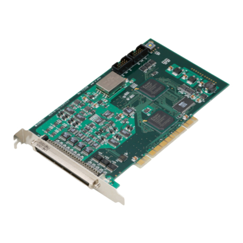
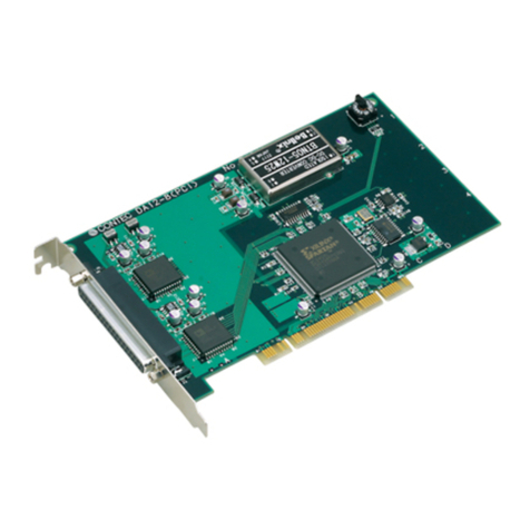
PCI-bus Analog Input Board
AD12-64(PCI)
Thisboard isinterface board ofthePCIbusconformity
whichinputsanalogsignaland performsconversion (AD
translation)to adigitalsignal.
Conversion speed:10µsec/ch, resolution:AD translation is
madein 12bits.
By usingattached APIfunction library API-PAC(W32), the
application softwareforWindowscan becreatedby the
variousprogramminglanguageswhicharesupporting
Win32APIfunctions, such asVisualBasic, and VisualC/
C++.
Features
-Multi-channelanaloginputcapability
64 single-ended analoginputsor32 differentialanalog
inputs. Single-ended ordifferentialinputisselected by
software.
-Multi-channelanaloginput
Analoginputofasingleand 64 inputs, and 32 differential
inputsispossible.
Selection ofasingleand input, and adifferentialinputcan
besetup by software.
-Inputrangesetup by software
Inputrangecan bechosen fromthefollowingrangesfor
everychannel, and can besetup by software.
±10V, ±5V, ±2.5V, ±1.25V, 0-+10V,0-+5V, 0-+2.5V,
0-+1.25V
-Inputrangesetup by software
Asamplingto thearbitrarytimingby softwareorthe
periodicsamplingwhich synchronized with thesampling
clock can beperformed.
Theselection ofexternalsamplingclocksignalwhich uses
thedigitalsignalinputted fromtheinternalsampling clock
whichusestheclock generatorofboardloading, and the
outsideispossibleforasamplingclock.
-DigitalI/Ofunction
IthasfourdigitalinputsofTTLlevel,and fourdigital
outputs, and themonitorofexternalapparatusand control
can beperformed.
-Option apparatus
Byusingoption apparatus,connection can beperformed
easily.
Pleasereferto"cableconnector"and "accessories"aboutan
option.
Cable & Connector (Option)
Cable (option)
96pinhalf96pin shield cable:PCB96PS-1.5
96pinhalf96pin flatcable:PCA96P-1.5
96pinhalf96pin shield cable:PCA96PS-1.5
Connector (Option)
96pin halfpitch (female)connector5piece set:
CN5-H96F
Accessories (Option)
Solderless relay terminalunit :EPD-96 *
* Option cablePCB96PS-1.5 isrequired separately.
Packing List
- Board [AD12-64(PCI)] - 1
- User's Guide - 1
- CD-ROM [API-PAC(W32)] - 1
Ver.3.00AD12-64(PCI)
2
Specification
Item AD12-64(PCI)
Analog input
Number of input
channels
64 single-ended input channels or 32 differential input channels
(specified by software)
Input range
Non-insulated bipolar ±10V, ±5V, ±2.5V, ±1.25V
or Non-insulated unipolar 0~10V, 0~5V, 0~2.5V, 0~1.25V
(specifiable by software for each channel)
Maximum input voltage
±15V
Input impedance
1M Ohm or higher
Resolution
12bit
Non-1inear error *1
±2LSB (±10V, ±5V, 0~10V. 0~5V range)
±4LSB (±2.5V, ±1.25V, 0~2.5V range)
±8LSB (0~1.25V range)
Conversion rate
10µsec/ch at Max.
Conversion start trigger
Software/sampling clock
Sampling clock
Internal sampling clock : 10,000~1,073,741,824,000nsec
(specified in steps of 250nsec)
External sampling clock : TTL-level falling edge
Digital input/output
Number of output points
Non-insulated 4 output points (TTL-level active high)
Number of input points
Non-insulated 4 input points (TTL-level active high)
Programmable timer
Specifiable cycles
500~1,073,741,824,000nsec (specifiable in steps of 250nsec)
Status
Count-up, count-up overrun
Timer output signal
TTL-level 250nesc low pulse, low output current IOL = 24mA
External trigger input
External trigger input signal
Non-insulated one point input (TTL-level rising edge)
Status
Trigger input, trigger input overrun
Interrupt
Interrupt level
1point
Interrupt source
8types
Interface connector
CN1
PCR-E96LMD (product of HONDA TUSUSHIN KOGYO Co.,
LTD.) or equivalent
General
I/O addresses
32ports occupied
Operating conditions
0~50°C, 20~90% (No condensation)
Current consumption *2
DC+5V 700mA (Max.)
Dimensions (mm)
176.4(L) x 107.0(H)
Weight
150g
*1
The nonlinearity error can be 0.1% of the maximum range at an ambient temperature of 0 or
50°C Celsius. The error can
be minimized by calibrating the board at the temperature equalto
the temperature of the operating environment.
*2
2 Current consumption increases if power (+5V) is supplied to an external device from
connector.
176.4
107.0
[mm]
Board size
AD12-64(PCI)Ver.3.00
3
External Connection
Connection method with a connector
by the interf ace connector on board (CN1).
The example of connection of option
Support Software
Attached support software
API Function Library API-PAC(W32)
It is the library software which offers the command to the
hardware of our company in standard Win32API function (DLL)
form for Windows.
By the various programming languages which are supporting
Win32API functions, such as Visual Basic, and Visual C/C++,
the high-speed application software which harnessed the spe-
cial feature of the hardware of our company can be created.
Moreover, it can use also for the check of hardware of opera-
tion by the installed diagnostic program.
For details, please refer to Help or the homepage of our com-
pany in appending CD-ROM.
Environment of operation
Main correspondence OS Windows 2000, NT, Me, 98, etc
Main adaptation languages Visual C++, Borland C++, Visual
Basic, etc.
Others The hard disk which has 20MB empty domain for ev-
ery library software is required.
The newest driver and download service (http://www.contec.
co.jp/apipac/) of difference file are also offered.
Optional Support Software
Collection for measurement systems development of ActiveX
components
ACX-PAC(W32)BP
It is the convenient measurement systems development tool
for Windows in which the collection of examples which can be
used immediately, and the collection (collection of software
parts) of components which can program easily only by com-
bining were mentioned.
Component for control of the input-and-output board (card) of
our company is made the one package. Analog I/O, digital I/O,
control of each interface of GPIB communication and X-Y graph
display, and file preservation are possible.
Collection for measurement systems development of ActiveX
components
ACX-PAC(W32)AP
In addition to the function of ACX-PAC(W32)BP, components,
such as display systems, such as various graph, switch, and
lamp, and operation / analysis, serve as a package.
DDE server DDE SERVER(W32)
It is the software which transmits to DDE client by the cycle
which specified the data from the hardware of our company, or
setup. Data collection / analysis system can be easily created
combining DDE client software, such as Excel97, and
Wonderware InTouch, Visual Basic.
Ver.3.00AD12-64(PCI)
4
Interface Connector
AD12-64(PCI) CN1Pin Assignmentsto Signals
Analog Input59/27[-]
Analog Input51/27[+]
Analog Input58/26[-]
Analog Input50/26[+]
Analog Input57/25[-]
Analog Input49/25[+]
Analog Input56/24[-]
Analog Input48/24[+]
Analog Ground
Analog Ground
Analog Input43/19[-]
Analog Input35/19[+]
Analog Input42/18[-]
Analog Input34/18[+]
Analog Input41/17[-]
Analog Input33/17[+]
Analog Input40/16[-]
Analog Input32/16[+]
Analog Ground
Analog Ground
Analog Input27/11[-]
Analog Input19/11[+]
Analog Input26/10[-]
Analog Input18/10[+]
Analog Input25/9[-]
Analog Input17/9[+]
Analog Input24/8[-]
Analog Input16/8[+]
Analog Ground
Analog Ground
Analog Input11/3[-]
Analog Input3/3[+]
Analog Input10/2[-]
Analog Input2/2[+]
Analog Input9/1[-]
Analog Input1/1[+]
Analog Input8/0[-]
Analog Input0/0[+]
Analog Ground
Analog Ground
Ext.Sampling ClockInput
Digit alGrou nd
Ext.TriggerInput
Digit alGrou nd
Digit alInput3
Digit alInput2
Digit alInput1
Digit alInput0
[49][1]
[96] [48]
B48
B47
B46
B45
B44
B43
B42
B41
B40
B39
B38
B37
B36
B35
B34
B33
B32
B31
B30
B29
B28
B27
B26
B25
B24
B23
B22
B21
B20
B19
B18
B17
B16
B15
B14
B13
B12
B11
B10
B09
B08
B07
B06
B05
B04
B03
B02
B01
A48
A47
A46
A45
A44
A43
A42
A41
A40
A39
A38
A37
A36
A35
A34
A33
A32
A31
A30
A29
A28
A27
A26
A25
A24
A23
A22
A21
A20
A19
A18
A17
A16
A15
A14
A13
A12
A11
A10
A09
A08
A07
A06
A05
A04
A03
A02
A01
Analog Input63/31[-]
Analog Input55/31[+]
Analog Input62/30[-]
Analog Input54/30[+]
Analog Input61/29[-]
Analog Input53/29[+]
Analog Input60/28[-]
Analog Input52/28[+]
Analog Grou nd
Analog Grou nd
Analog Input47/23[-]
Analog Input39/23[+]
Analog Input46/22[-]
Analog Input38/22[+]
Analog Input45/21[-]
Analog Input37/21[+]
Analog Input44/20[-]
Analog Input36/20[+]
Analog Grou nd
Analog Grou nd
Analog Input31/15[-]
Analog Input23/15[+]
Analog Input30/14[-]
Analog Input22/14[+]
Analog Input29/13[-]
Analog Input21/13[+]
Analog Input28/12[-]
Analog Input20/12[+]
Analog Grou nd
Analog Grou nd
Analog Input15/7[-]
Analog Input7/7[+]
Analog Input14/6[-]
Analog Input6/6[+]
Analog Input13/5[-]
Aanalog Input5/5[+]
Analog Input12/4[-]
Analog Input4/4[+]
Analog Grou nd
Analog Grou nd
+5VDCfromPC
+5VDCfromPC
Sampling Busy
TimerOutpu t
DigitalOutpu t3
DigitalOutpu t2
DigitalOutpu t1
DigitalOutpu t0
*Pinnu mbersinparentheses"[]"complywit hthosedefinedby
HONDATSUSHINKOGYO CO., LTD.
Analog Input 0
to Analog Input 63 Analog input signals in single-ended input mode.
The numbers correspond to channel numbers.
Analog Input 0 [+]
to Analog Input 31 [+] Analog input signals in differential inputs.
The numbers correspond to channel numbers.
Analog Input 0 [-]
to Analog Input 31 [-]Analog input signals in differential inputs.
The numbers correspond to channel numbers.
Analog Ground Analog ground common to analog I/O signals.
Digital Input 0 to Digital Input 3 Digital input signal.
Digital Output 0 to Digital Output 3
Digital output signal.
External Trigger Input External trigger input signal.
External Sampling Clock Input External sampling clock input signal.
Timer Output Timer output signal
Sampling Busy output Sampling busy output signal
+5V DC from PC Supplies 1 ampere of current at +5 volts.
Digital Ground Digital ground common to "Simultaneous Hold
Output" and "+5V DC from PC".
Notes!
-Do notconnectanyoftheoutputsand poweroutputsto theanalog ordigitalground.
-Neitherconnectoutputsto each other.
-Doing eithercan result in a fault.
AD12-64(PCI)Ver.3.00
5
AD12-16(PCI) CN1Pin Assignmentsto Signals
N.C.
N.C.
N.C.
N.C.
N.C.
N.C.
N.C.
N.C.
Analog Ground
Analog Ground
N.C.
N.C.
N.C.
N.C.
N.C.
N.C.
N.C.
N.C.
Analog Ground
Analog Ground
N.C.
N.C.
N.C.
N.C.
N.C.
N.C.
N.C.
N.C.
Analog Ground
Analog Ground
Analog Input11/3[-]
Analog Input3/3[+]
Analog Input10/2[-]
Analog Input2/2[+]
Analog Input9/1[-]
Analog Input1/1[+]
Analog Input8/0[-]
Analog Input0/0[+]
Analog Ground
Analog Ground
Ext.Sampling ClockInput
DigitalGround
Ext.TriggerInput
DigitalGround
DigitalInput3
DigitalInput2
DigitalInput1
DigitalInput0
[49] [1]
[96] [48]
B48
B47
B46
B45
B44
B43
B42
B41
B40
B39
B38
B37
B36
B35
B34
B33
B32
B31
B30
B29
B28
B27
B26
B25
B24
B23
B22
B21
B20
B19
B18
B17
B16
B15
B14
B13
B12
B11
B10
B09
B08
B07
B06
B05
B04
B03
B02
B01
A48
A47
A46
A45
A44
A43
A42
A41
A40
A39
A38
A37
A36
A35
A34
A33
A32
A31
A30
A29
A28
A27
A26
A25
A24
A23
A22
A21
A20
A19
A18
A17
A16
A15
A14
A13
A12
A11
A10
A09
A08
A07
A06
A05
A04
A03
A02
A01
N.C.
N.C.
N.C.
N.C.
N.C.
N.C.
N.C.
N.C.
Analog Ground
Analog Ground
N.C.
N.C.
N.C.
N.C.
N.C.
N.C.
N.C.
N.C.
Analog Grou nd
Analog Grou nd
N.C.
N.C.
N.C.
N.C.
N.C.
N.C.
N.C.
N.C.
Analog Grou nd
Analog Grou nd
Analog Input15/7[-]
Analog Input7/7[+]
Analog Input14/6[-]
Analog Input6/6[+]
Analog Input13/5[-]
Analog Input5/5[+]
Analog Input12/4[-]
Analog Input4/4[+]
Analog Grou nd
Analog Grou nd
+5VDCfromPC
+5VDCfromPC
Sampling Busy
TimerOutput
Digit alOutpu t3
Digit alOutpu t2
Digit alOutpu t1
Digit alOutpu t0
*Pinnumbersinparentheses"[]"complywiththosedefinedby
HONDATSUSHINKOGYO CO., LTD.
Analog Input 0
to Analog Input 15 Analog input signals in single-ended input mode.
The numbers correspond to channel numbers.
Analog Input 0 [+]
to Analog Input 7 [+] Analog input signals in differential inputs.
The numbers correspond to channel numbers.
Analog Input 0 [-]
to Analog Input 7 [-]Analog input signals in differential inputs.
The numbers correspond to channel numbers.
Analog Ground Analog ground common to analog I/O signals.
Digital Input 0
to Digital Input 3 Digital input signal.
Digital Output 0
to Digital Output 3 Digital output signal.
External Trigger Input External trigger input signal.
External Sampling Clock Input External sampling clock input signal.
Timer Output Timer output signal
Sampling Busy output Sampling busy output signal
+5V DC from PC Supplies 1 ampere of current at +5 volts.
Digital Ground
Digital ground common to "Simultaneous Hold Output"
and "+5V DC from PC".
N.C. No connection to this pin.
Notes!
-Do notconnectanyoftheoutputsand poweroutputsto theanalog ordigitalground.
-Neitherconnectoutputsto each other.
-Doing eithercan result in a fault.
Ver.3.00AD12-64(PCI)
6
Analog Input Connection
Theinputformofanalogsignalhasasingleand input, and differentialinput,and theconnection methodswithasignaldiffer,
respectively. Here, theexamplein thecaseofconnecting usingaflatcableorashieldcableisshown.
Single-ended Input
Itisan exampleofconnection when usingaflatcable.
Thesource ofasignaland aground areconnected to 1 to 1 to each analog inputchannelofCN1.
Analog Input0...63
Analog Ground V
BOARDCN1 Cable Signal Source
*1
*1 0...15 on theAD12-16 (PCI) board
Itistheexampleofconnection which used theshield cable. Whenthedistance ofthesource ofasignaland aboardislong,please
useit to enlargenoise-proofnature. To eachanaloginputchannelofCN1, wirelineisconnectedto signallineand thegroup edited
by theshield isconnected to aground.
Analog Ground
Shieldcable
Analog Input0...63
BOARDCN1SignalSource
V
*1
*1 0...15 on theAD12-16 (PCI) board
Notes!
-Frequency componentshigherthan 1MHzcontained in a signalmaycausecrosstalkacross channels.
- When a frequency ingredient1MHzormoreiscontained in thesource ofsignal, thecross talkbetween channelsmayoccur.
- When a board and thesource ofa signalareinfluenced ofa noise, orwhen thedistance ofa board and thesource ofa signalis
long, it maybeunableto inputin exactdata bytheconnection method.
-Analog signalto inputmustnotexceed themaximuminputvoltageon thebasisoftheanalog ground ofa board. Aboard may
bedamaged when it exceeds.
-Conversion data isunknown when inputterminalisnotconnected. Pleaseconnectwith analog ground too hastilytheinput
terminalofa channelwhich isnotconnected to thesource ofa signal.
Differential input mode
Itisan exampleofconnection when usingaflatcable.
[+]inputofeachanaloginputchannelofCN1 isconnected to asignal,and [-] inputisconnected to theground ofthesourceofa
signal. Furthermore, theanalogground ofaboard and theground ofthesource ofasignalareconnected.
Analog Input0[+]...31[+]
Analog Ground
BOARDCableSignalSource
Analog Input0[-]...31[-]
CN1
V
*2
*2 0[+]...7[+]and 0[-]...7[-] arerespectivelyapplicabletoAD12-16(PCI).
Itistheexampleofconnection which used 2 heartshield cableetc. When thedistance ofthesource ofasignaland aboard islong,
pleaseuseit toenlargenoise-proofnature. [+]inputofeach analoginputchannelofCN1 isconnected toasignal,and [-] inputis
connected to theground ofthesourceofasignal. Furthermore, theanalog ground ofaboard and theground ofthesource ofasignal
areconnected in thegroup editedby theshield.
Analog Input0[+]...31[+]
Analog Ground
V
BOARDSignal Source
Analog Input0[-]...31[-]
CN1Shield cable
*2
*2 0[+]...7[+]and 0[-]...7[-]arerespectively applicableto AD12-16(PCI).
Notes!
- When a frequency ingredient1MHzormoreiscontained in thesource ofsignal, thecross talkbetween channelsmayoccur.
-Conversion data becomesunfixed when analog ground isnotconnected.
- When a board and thesource ofa signalareinfluenced ofa noise, orwhen thedistance ofa board and thesource ofa signalis
long, it maybeunableto inputin exactdata bytheconnection method.
-Analog signalinputted into [+]inputand [-]inputmustnotexceed themaximuminputvoltageon thebasisofanalog ground of
a board. Aboard maybedamaged when it exceeds.
-Conversion data when having notconnected terminalof[+]inputor[-]inputisunfixed. Both should connectwith an analog
ground too hastilytheterminalof[+]inputofthechannelwhich doesnotconnectwith thesource ofa signal, and [-]input.
AD12-64(PCI)Ver.3.00
7
Connection of Digital and control signal
Theexamplein thecaseofconnectingadigitalI/Osignaland controlsignals(externalsamplingclock inputsignal, "SamplingBusy
Output", etc.)usingaflatcableisshown.
CN1 and externalapparatusareconnected using optionalflatcable(PCA96P-1.5)etc.
All ofthesedigitalI/Osignalsand acontrolsignalarethesignalsofTTL level.
Connecting the Control Signal Inputs
DigitalGround
TargetCableCN1
Input
10kΩ
BOARDALS 540 orequivalent
Connecting the Control Signal Outputs
DigitalGround
TargetCableCN1Output
IOL=24mA
BOARDALS540 orequivalent
Notes!
-Pleaseconnecteach outputneitherwith analog ground nora digitalground too hastily. Itbecomesthecauseoffailure.
Block Diagram
64/16 single-end /
32/8 differential
Analog Inputs
4Digital Input /4Digital Output
External Sampling Clock Input /
External Trigger Input
Timer Output /Sampling Busy Output
PCIbus
CN1
FPGA
Multiplexer
DC/DC
converter
Instrument
Amplifre
A/D
Converter

Other manuals for AD12-64(PCI)

2

Other Contec PCI Card manuals

Contec COM-4(PCI)H User manual

Contec

Contec COM-4(PCI)H User manual

Contec GPIB-F-LPE User manual

Contec

Contec GPIB-F-LPE User manual

Contec PC-HELPER Series User manual

Contec

Contec PC-HELPER Series User manual

Contec DIO-48D-LPE User manual

Contec

Contec DIO-48D-LPE User manual

Contec DI-64T2-PCI User manual

Contec

Contec DI-64T2-PCI User manual
Contec CNT24-4(PCI) User manual

Contec

Contec CNT24-4(PCI) User manual

Contec IPC SERIES User manual

Contec

Contec IPC SERIES User manual

Contec AD12-64(PCI) User manual

Contec

Contec AD12-64(PCI) User manual

Contec FX-DS540-MPCI6 User manual

Contec

Contec FX-DS540-MPCI6 User manual

Contec IPC SERIES User manual

Contec

Contec IPC SERIES User manual

Contec ADI12-16(PCI) User manual

Contec

Contec ADI12-16(PCI) User manual

Contec COM-1(LPCI)H User manual

Contec

Contec COM-1(LPCI)H User manual

Contec SMC-8DL-PCI User manual

Contec

Contec SMC-8DL-PCI User manual

Contec CNT24-4D(PCI)H User manual

Contec

Contec CNT24-4D(PCI)H User manual

Contec CNT24-4 User manual

Contec

Contec CNT24-4 User manual

Contec AI-1216B-RB1-PCI User manual

Contec

Contec AI-1216B-RB1-PCI User manual

Contec DIO-96D-LPE User manual

Contec

Contec DIO-96D-LPE User manual

Contec CFast CFS-32GBM-A User manual

Contec

Contec CFast CFS-32GBM-A User manual

Contec DIO-32DM2-PE User manual

Contec

Contec DIO-32DM2-PE User manual

Contec PIO-16/16RL(PCI)H User manual

Contec

Contec PIO-16/16RL(PCI)H User manual

Contec DIO-3232LX-USB User manual

Contec

Contec DIO-3232LX-USB User manual

Contec AD16-64(LPCI)LA User manual

Contec

Contec AD16-64(LPCI)LA User manual

Contec DIO-1616T-LPE User manual

Contec

Contec DIO-1616T-LPE User manual
Contec DIO-1616B-LPE User manual

Contec

Contec DIO-1616B-LPE User manual

Popular PCI Card manuals by other brands

Advantech B+B SmartWorx McPC/Giga-MediaLinX user manual

Advantech

Advantech B+B SmartWorx McPC/Giga-MediaLinX user manual

DeLOCK 89015 user manual

DeLOCK

DeLOCK 89015 user manual

Lindy 51245 user manual

Lindy

Lindy 51245 user manual

SMC Networks 2512W-B FICHE user guide

SMC Networks

SMC Networks 2512W-B FICHE user guide

RSA 4 Series installation guide

RSA

RSA 4 Series installation guide

Aceex ISDN-PCI/N datasheet

Aceex

Aceex ISDN-PCI/N datasheet

IOGear GICe720S3W6 installation guide

IOGear

IOGear GICe720S3W6 installation guide

Broadcom BCM94321COEX2 user guide

Broadcom

Broadcom BCM94321COEX2 user guide

TRENDnet TEW-443PI datasheet

TRENDnet

TRENDnet TEW-443PI datasheet

Panasonic KX-TDA0174 Service manual

Panasonic

Panasonic KX-TDA0174 Service manual

AMD ATI TV Wonder 650 PCIe user guide

AMD

AMD ATI TV Wonder 650 PCIe user guide

Exsys EX-42062 user manual

Exsys

Exsys EX-42062 user manual

ADLINK Technology cPCI-6210 Series user manual

ADLINK Technology

ADLINK Technology cPCI-6210 Series user manual

Measurement Computing PCI-QUAD04 user manual

Measurement Computing

Measurement Computing PCI-QUAD04 user manual

Rosewill RC302 user manual

Rosewill

Rosewill RC302 user manual

Buffalo WLI2-PCI-G54S Quick setup guide

Buffalo

Buffalo WLI2-PCI-G54S Quick setup guide

KTI Networks Gigabit Ethernet PCI Adapter KG-502T Specifications

KTI Networks

KTI Networks Gigabit Ethernet PCI Adapter KG-502T Specifications

Kvaser Mini PCI Express HS user guide

Kvaser

Kvaser Mini PCI Express HS user guide

manuals.online logo
manuals.online logoBrands
  • About & Mission
  • Contact us
  • Privacy Policy
  • Terms and Conditions

Copyright 2025 Manuals.Online. All Rights Reserved.