manuals.online logo
Brands
  1. Home
  2. •
  3. Brands
  4. •
  5. Contec
  6. •
  7. PCI Card
  8. •
  9. Contec AO-1604CI3-PCI User manual

Contec AO-1604CI3-PCI User manual

Ver.1.02
AO-1604CI3-PCI 1
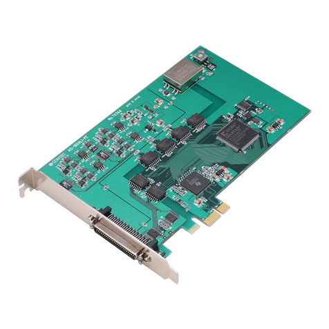
Isolated Analog Output Board for PCI
AO-1604CI3-PCI
* Specifications, color and design of the products are subject to change
without notice.
This product is a PCI bus supported board that extends the analog signal
output functions of a PC. Equipped with four channels of 16-bit analog
output, the product is an individual isolation model using a D/A
converter for each channel to provide isolation for the bus line with PC
and between channels. The voltage/current output range (voltage :
±10V, 0 - +10V; current : 0 - 20mA) can be set by jumper for each
channel. This product can generate signals that are synchronized with
the internal timer or an external clock. Windows/Linux driver is bundled
with this product.
Using the dedicated library VI-DAQ makes it possible to create each
application for LabVIEW.
Features
Analog output 4ch, 16bit-resolution, conversion speed 20µsec
This product has the Analog output (4ch, 16bit, 20µsec).
Additionally, the voltage/current output range (voltage : ±10V, 0 - +10V,
current : 0 - 20mA) can be set by jumper for each channel.
PC bus line, opto-coupler isolation between channels
The opto-couplers mounted for each channel provide electric isolation
between channels as well as between the inside of the board (PC) and
output pins.
Simultaneous output of voltage to a specified channel or all channels
This product can generate output voltage either for a specified channel
only or for all of the channels simultaneously. This can be selected or set
by software.
Windows/Linux compatible driver libraries are attached.
Using the attached driver library API-PAC(W32) makes it possible to
create applications of Windows/Linux. In addition, a diagnostic
program by which the operations of hardware can be checked is
provided.
Control of sampling start/stop can be selected by an external trigger
or other factor
Control of sampling start can be selected by software or an external
trigger. Control of sampling start and control of sampling stop are
independent from each other; therefore, they can be set separately.
Control of sampling stop can be selected by completion of a specified
number of sessions or an external trigger. In addition, when an error
occurs, sampling is stopped, regardless of the settings for sampling stop
conditions.
A sampling cycle can be selected from the internal clock (high precision
timer mounted on the board) or an external clock (control signal entered
from outside).
Relay provided to control output voltage
The mounted relay prevents unstable output voltage from being
generated upon power-up. This protects the connected devices from
damage and malfunction, as the output voltage for all the channels is
generated via the relay.
LabVIEW is supported by a plug-in of dedicated library VI-DAQ
Using the dedicated library VI-DAQ makes it possible to create each
application for LabVIEW.
Specifications
Item Specification
Analog Output
Isolated specification
Isolated independently
Number of output channels
4ch
Output range
Bipolar ±10V, Unipolar 0 - +10V
0 - 20mA (Jumper setting by channel)
Absolute max. output
current
±5mA (Voltage output) ±10V, 0 - +10V
Load register (Max.)
500 (Current output)
Output impedance
10  or less (Voltage output)
Resolution
16bit
Non-Linearity error *1
±5LSB (±10V, 0 - +10V), ±15LSB (0 - 20mA)
Conversion speed
20 sec (Max.)
Voltage output control relay
AQY221N2SX (Matsushita Electric Works, Ltd.) or equivalent to it
Sampling clock
Internal sampling clock : 20,000 - 1,073,741,824,000nsec (Can be set in 250n sec
units)
External sampling clock : opto-coupler isolated input
(corresponding to current sink output)
Programmable timer
Setting frequency
500 - 1,073,741,824,000nsec (Can be set in 250n sec units)
Timer output signal
Opto-coupler isolated open collector output (current sink type)
External trigger input
External trigger input signal
Opto-coupler isolated input (corresponding to sink output)
Status
Trigger input, trigger input overrun
I/O address
32 ports boundary
Interrupt level
1 point
Isolation voltage
500Vrms
Power consumption
+5VDC 2400mA (Max.)
Operating condition
0 - 50ºC, 10 - 90%RH (No condensation)
Bus specification
PCI (32bit, 33MHz, Universal key shapes supported *2)
External dimensions (mm)
176.41(L) x 105.68(H)
Used connector
37-pin D-SUB connector [F(Male) type]
DCLC-J37SAF-20L9E [mfd.by JAE] equivalent to it
Weight
160g
Standard
VCCI Class A, CE Marking (EMC Directive Class A, RoHS Directive)
*1 When the environment temperature is near 0ºC or 50ºC, the non-linearity error may become larger.
The error can be reduced by calibrating under the actual temperature conditions.
*2 The board requires +5V power supply from the expansion slot (it does not work in a +3.3V environment).
Board Dimensions
[mm]
176.4 1(L)
105.68(H)
The standa rd outside dimension (L) is the distance from the end
of t he board to t he outer surfa ce of the slot cover.
Ver.1.02
AO-1604CI3-PCI 2
Support Software
Windows version of digital I/O driver API-AIO(WDM)
[Stored on the bundled disk driver library API-PAC(W32)]
The API-AIO(WDM) is the Windows version driver library software that
provides products in the form of Win32 API functions (DLL). Various
sample programs such as Visual Basic and Visual C++, etc and diagnostic
program useful for checking operation is provided.
For more details on the supported OS, applicable language and new
information, please visit the CONTEC’s Web site.
Linux version of digital I/O driver API-AIO(LNX)
[Stored on the bundled disk driver library API-PAC(W32)]
The API-AIO(LNX) is the Linux version driver software which provides
device drivers (modules) by shared library and kernel version. Various
sample programs of gcc are provided.
For more details on the supported OS, applicable language and new
information, please visit the CONTEC’s Web site.
Data acquisition VI library for LabVIEW VI-DAQ
(Available for downloading (free of charge) from the CONTEC web
site.)
This is a VI library to use in National Instruments LabVIEW. VI-DAQ is
created with a function form similar to that of LabVIEW's Data Acquisition
VI, allowing you to use various devices without complicated settings.
For more details on the library and download of VI-DAQ, please visit the
CONTEC’s Web site.
Cable & Connector
Cable (Option)
Shielded Cable with Two 37-pin D- SUB Connectors
: PCB37PS-0.5P (0.5m), PCB37PS-1.5P (1.5m)
Flat Cable with Two 37-pin D- SUB Connectors
: PCB37P-1.5 (1.5m)
Shielded Cable with One 37-pin D- SUB Connector
: PCA37PS-0.5P (0.5m), PCA37PS-1.5P (1.5m)
Flat Cable with One 37-pin D- SUB Connector
: PCA37P-1.5 (1.5m)
Accessories
Accessories (Option)
Screw Terminal (M3 x 37P) : EPD-37A *1*2
Screw Terminal (M3.5 x 37P) : EPD-37 *1
General Purpose Terminal (M3 x 37P) : DTP-3C *1
Screw Terminal (M2.5 x 37P) : DTP-4C *1
*1 PCB37PS -*P optional cable is required separately (0.5m is recommended.).
*2 "Spring-up" type terminal is used to prevent terminal screws from falling off.
Packing List
Board [AO-1604CI3-PCI] …1
First step guide … 1
Disk *1 [API-PAC(W32)] …1
Warranty Certificate …1
Serial number label …1
*1 The bundled disk contains the driver software and User’s Guide
Connector Pin Assignment
Voltage Output 0
- Voltage Output3
Analog voltage output signal.
The numbers correspond to channel numbers.
Current Output 0
- Current Output 3
Analog current output signal.
The numbers correspond to channel numbers.
Analog Ground 0
- Analog Ground 3
Analog grounds for identically numbered output signals.
External Trigger Input
External trigger input signal
External Sampling Clock
Input
External sampling clock input signal.
Timer Output
Output signal of programmable timer
Settling Busy Output
Output signal indicating that the board is performing DA conversion.
Plus Common
Connect the plus side of external device.
Common for each "External Trigger Input", "External Sampling Clock Input", "Timer
Out", "Settling Busy Output" signal.
Minus Common
Connect the minus side of external device.
Common for each "Timer Out", "Settling Busy Output" signal.
N.C.
No connection to this pin.
▼CAUTION
Do not connect any of the outputs and power outputs to the analog or digital ground.
Neither connect outputs to each other. Doing either can result in a fault.
Analog Output Signal Connection
The sections below describe how to connect the signals using flat cable
and shielded cable.
Connecting example of voltage output
The following figure shows an example of optional flat cable (PCA37P)
connection. Connect the CN1 analog output channels and ground to the
external device's input and ground.
Connection of voltage output (Flat Cable)
The following example connects a signal source to the board using a
shielded cable. Use shielded cable if the distance between the board
and loading is long or if you want to provide better protection from
noise. Use the core of the shielded cable to connect the analog output
of CN1 to the input of the external device and use the shield braid to
connect the CN1's analog ground to the external device's ground.
Analog Output Connection (Shield Cable)
▼CAUTION
- If the board and the target receive noise or the distance between the board and the signal source is too long,
data may not be input properly.
- The maximum output current-carrying capacity of the analog output signal is ±5 mA. Check the
specifications of the target before connecting the board to it.
CN1
19
18
17
16
15
14
13
12
11
10
9
8
7
6
5
4
3
2
1
Settling Busy Output
Timer Output
Minus Common
N.C.
N.C.
Analog Ground 3
N.C.
N.C.
N.C.
Analog Ground 2
N.C.
N.C.
N.C.
Analog Ground 1
N.C.
N.C.
N.C.
Analog Ground 0
37
36
35
34
33
32
31
30
29
28
27
26
25
24
23
22
21
20
Plus Common
External Trigger Input
External Sampling Clock Input
N.C.
N.C.
Current Output 3
Voltage Output 3
N.C.
N.C.
Current Output 2
Voltage Output 2
N.C.
N.C.
Current Output 1
Voltage Output 1
N.C.
N.C.
Current Output 0
Voltage Outpu 0
Voltage Output 0...3
Analog Ground 0...3
Target
BOARD Cable
CN1
Digital Multi-Meter etc.
MOSFET Relay
+
-
CN1 Target
Coaxial cable
Voltage Output 0...3
Analog Ground 0...3
BOARD MOSFET Relay
Digital Multi-Meter etc.
+
-
Ver.1.02
AO-1604CI3-PCI 3
- Do not connect any of the outputs and power outputs to the analog or digital ground.
- Do not connect the analog output signal to the other analog output signal and output signal of external
device. Doing so may malfunction.
- Do not plug or unplug the interface connector to or from while the PC or external device power is turned on.
Doing so may malfunction.
- The DA converter may cause glitches as it contains no deglitcher.
Connecting example of current output
The figure below shows an example connection using a flat cable as the
optional one (PCA37P).
The load register is connected. Please adjust the register load RL
connected with the current output of each channel to 500 or less
including the resistance of wiring.
Each current output of CN1 and analog ground is connected to the
resister load RL.
Current output connection (Flat cable)
The following figure shows an example of shielded cable connection.
Use shielded cable if the distance between the loading and board is long
or if you want to provide better protection from noise. Connect the
each current output of CN1 to the register load in the core wire of
shielded cable and connect the each analog ground of CN1 to the
register load in the shielding of shielded cable.
Current output connection (Shielded cable)
▼CAUTION
- Do not short the output signals to analog ground, digital ground, and/or power line. Doing so may damage
the board.
- If connected to each output, a pull-up resistor must be about 10 k to pull up with a 3.3V power source.
- Each input accepts 5V TTL signals.
Control signals Connection
Input signals connection
To the “External Sampling Clock Input” and “External Start Trigger Input”,
connect current driven devices such as a switch and a transistor output
device. Input circuit is as follows. An external power supply is required
to drive the input circuit. The power capacity required at this time is
about 11 mA per input channel at 24 VDC (or about 5.5 mA at 12 VDC).
Input circuit
Connection example with open-collector output (current sink type)
Connection example with mechanical contact point
The relation of the data (internal logic) seen from the input signal and the
PC side as an example of the above figure is shown below.
Relation between the input signal and the data (internal logic) seen
from the PC side
Internal logic
Contact point
Input pin voltage level
0 OFF High
1 ON Low
Output signals connection
To the “Timer Output “ and “Settling Busy Output”, connect a relay
controller or a current driven control device such as a LED. Output circuit
is as follows.
An external power supply is required to drive the output circuit. The rated
output current is up to 50 mA per channel. The output transistor is not
associated with a surge voltage protection circuit. When the output
signal is used to drive the inductive load to a relay or lamp, apply surge
protection to the load side.
Output circuit
▼CAUTION
When the power supply is turned on, all the outputs are turned off.
Current Output 0...3
Analog Ground 0...3
Target
BOARD Cable
CN1
Register load RL
CN1 TargetCoaxial cable
Analog Ground 0...3
Current Output 0...3
BOARD
Register load R
L
+Common
External
Trigger
Input
External
Sampling
Clock
Input
SW
External circuit
Board
External power supply
12V - 24VDC
Vcc
Opto-coupler
HCPL-M452
Vcc
HCPL-M452
Vcc
Vcc
Internal circuit
Opto-coupler
SW
Internal circuit
10kΩ
2.2kΩ
10kΩ
2.2kΩ
Input pin
+Common
Vcc
Vcc
External power supply
+12V - +24VDC
External device
Plus common
Open-collector
output
Minus common
Board
Internal
circuit
+Common
Vcc
Vcc
+12V - +24VDC
Contact point
Board
External power supply
Internal
circuit
Input pin
HCPL-0531
Vcc Vcc
2SD178 2K
2SD178 2K
-Common
Sa mpling
Busy
Output
+Common
Timer
Output
Board Ex terna l circuit
Opt o-coupler
Internal
circuit
Internal
circuit
Loa di ng
L oad in g
Opt o-coupler
100Ω100Ω
15kΩ15kΩ
External power
supply
12V - 24VDC
Ver.1.02
AO-1604CI3-PCI 4
Connection example with current sink corresponding input
Connection example with TTL level input (with pull-up register)
Difference from AO-1604CI2-PCI and
DAI16-4C(PCI)
This product is a successor of the previous model
AO-1604CI2-PCI and DAI16-4C(PCI). So you can use the
same operating procedures as AO-1604CI2-PCI and
DAI16-4C(PCI).
AO-1604CI3-PCI
AO-1604CI2-PCI
DAI16-4C(PCI)
About the
display of the
mounted
board name
DAI16-4C(PCI) *1 DAI16-4C(PCI) *1 DAI16-4C(PCI)
Environmental
support
Product for RoHS instruction Product for RoHS instruction Lead decrease product
Appearance
External
dimensions
(mm)
176.41(L)×105.68(H) 176.41(L)×106.68(H) 176.41(L)×106.68(H)
*1: Even if this product is installed, the displayed board name is “DAI16-4C(PCI)".
There is no problem in operation even if the board name is displayed as “DAI16-4C(PCI)".
-Common
+Common
Vcc External device
+12V - +24VDC
Output pin
External power supply
Plus common
Board
Internal
circuit
Input
Vcc
+12V - +24VDC
+5V
-Common
+Common
TTL level input
Ground
Board
External power supply
External device
Output pin
Internal
circuit

Other manuals for AO-1604CI3-PCI

1

Other Contec PCI Card manuals

Contec AI-1216B-RB1-PCI User manual

Contec

Contec AI-1216B-RB1-PCI User manual

Contec DIO-3232LX-USB User manual

Contec

Contec DIO-3232LX-USB User manual

Contec CNT24-4 User manual

Contec

Contec CNT24-4 User manual

Contec COM-1(LPCI)H User manual

Contec

Contec COM-1(LPCI)H User manual

Contec SMC-4DF-PCI User manual

Contec

Contec SMC-4DF-PCI User manual

Contec DIO-1616T-LPE User manual

Contec

Contec DIO-1616T-LPE User manual

Contec GPIB-F-LPE User manual

Contec

Contec GPIB-F-LPE User manual

Contec FX-DS540-MPCI4W User manual

Contec

Contec FX-DS540-MPCI4W User manual

Contec DIO-1616B-LPE User manual

Contec

Contec DIO-1616B-LPE User manual

Contec PIO-16/16RL(PCI)H User manual

Contec

Contec PIO-16/16RL(PCI)H User manual

Contec AD16-64(LPCI)LA User manual

Contec

Contec AD16-64(LPCI)LA User manual

Contec DA12-8PCI User manual

Contec

Contec DA12-8PCI User manual

Contec FX-DS540-MPCI6 User manual

Contec

Contec FX-DS540-MPCI6 User manual

Contec PIO-64/64L(PCI)H User manual

Contec

Contec PIO-64/64L(PCI)H User manual

Contec DIO-0808L-PCI User manual

Contec

Contec DIO-0808L-PCI User manual

Contec PC-HELPER Series User manual

Contec

Contec PC-HELPER Series User manual

Contec COM-2(PCI)H User manual

Contec

Contec COM-2(PCI)H User manual

Contec ADI12-16(PCI) User manual

Contec

Contec ADI12-16(PCI) User manual

Contec AIO-160802LI-PE User manual

Contec

Contec AIO-160802LI-PE User manual

Contec CFast CFS-32GBM-A User manual

Contec

Contec CFast CFS-32GBM-A User manual

Contec DIO-48D-LPE User manual

Contec

Contec DIO-48D-LPE User manual

Contec PI-64L Series User manual

Contec

Contec PI-64L Series User manual

Contec IPC SERIES User manual

Contec

Contec IPC SERIES User manual

Contec DI-64T2-PCI User manual

Contec

Contec DI-64T2-PCI User manual

Popular PCI Card manuals by other brands

Conrad 46 93 89 operating instructions

Conrad

Conrad 46 93 89 operating instructions

D-Link DGE-528T manual

D-Link

D-Link DGE-528T manual

SIIG LB-US0314-S1 installation guide

SIIG

SIIG LB-US0314-S1 installation guide

Cognex DSMax Frame Grabber Installation and Reference

Cognex

Cognex DSMax Frame Grabber Installation and Reference

National Instruments PCI-6509 user guide

National Instruments

National Instruments PCI-6509 user guide

Linksys RangePlus WMP110 user guide

Linksys

Linksys RangePlus WMP110 user guide

Portwell WADE-8021 user manual

Portwell

Portwell WADE-8021 user manual

DeLOCK 90090 user manual

DeLOCK

DeLOCK 90090 user manual

MEN Mikro Elektronik F602 user manual

MEN Mikro Elektronik

MEN Mikro Elektronik F602 user manual

Datapath VisionLC-HD manual

Datapath

Datapath VisionLC-HD manual

Kontron 0-0096-4514 user guide

Kontron

Kontron 0-0096-4514 user guide

DAQ system PCI-AIO05 user manual

DAQ system

DAQ system PCI-AIO05 user manual

Fluke AirMagnet Read me first

Fluke

Fluke AirMagnet Read me first

GoMax Electronics PCIE-502MJZ user manual

GoMax Electronics

GoMax Electronics PCIE-502MJZ user manual

Avermedia Live Gamer Extreme GC550 quick guide

Avermedia

Avermedia Live Gamer Extreme GC550 quick guide

Matrox Morphis QxT Installation and Hardware Reference

Matrox

Matrox Morphis QxT Installation and Hardware Reference

ICS Advent WDT1000-P product manual

ICS Advent

ICS Advent WDT1000-P product manual

Addi-Data PC104-PLUS1500 Technical description

Addi-Data

Addi-Data PC104-PLUS1500 Technical description

manuals.online logo
manuals.online logoBrands
  • About & Mission
  • Contact us
  • Privacy Policy
  • Terms and Conditions

Copyright 2025 Manuals.Online. All Rights Reserved.