manuals.online logo
Brands
  1. Home
  2. •
  3. Brands
  4. •
  5. Continental Hydraulics
  6. •
  7. Control Unit
  8. •
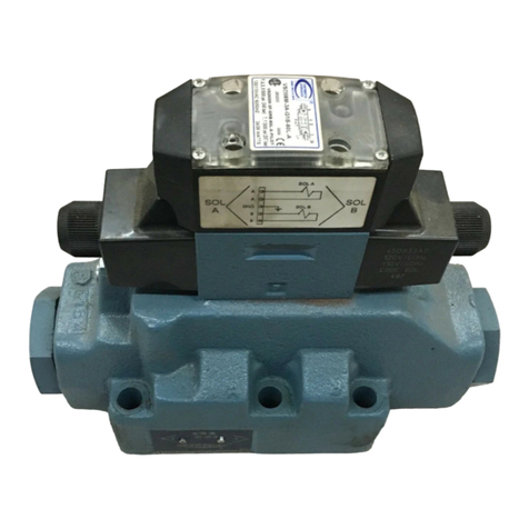
  9. Continental Hydraulics A Design Series User manual

Continental Hydraulics A Design Series User manual

CAUTION – Before performing any service
operation on any Directional Control Valve,
be sure that all pressure has been relieved
from BOTH SIDES of the system.
CAUTION – Before performing any service
operation on any Directional Control Valve,
disconnect or lock off power supply.
CAUTION – Before manually actuating any
Directional Control Valve, be sure that any
resulting machine function will not endanger
persons or equipment.
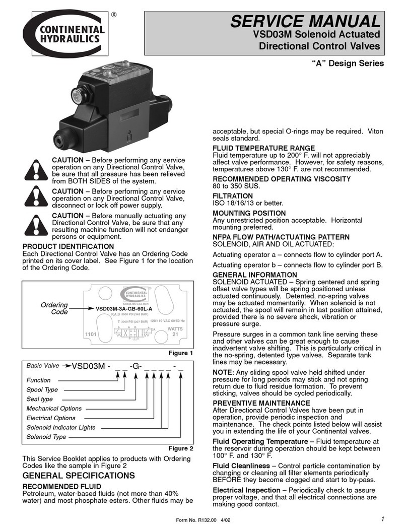
PRODUCT IDENTIFICATION
Each Directional Control Valve has an Ordering Code
stamped on its top label. See Figure 1 for the location
of the Ordering Code.
This Service Booklet applies to products with Ordering
Codes like the sample in Figure 2.
GENERAL SPECIFICATIONS
RECOMMENDED FLUID
Petroleum, water-based fluids (not more than 40%
water) and most phosphate esters. Other fluids may be
acceptable, but special O-rings may be required. Viton
seals standard.
FLUID TEMPERATURE RANGE
Fluid temperature up to 200° F. (93° C.) will not
appreciably affect valve performance. However, for
safety reasons, temperatures above 130° F. (54° C.)
are not recommended.
RECOMMENDED OPERATING VISCOSITY
80 to 350 SUS (16 to 70 cSt).
FILTRATION
ISO 18/16/13 or better.
MOUNTING POSITION
Any unrestricted position acceptable. Horizontal
mounting preferred.
NFPA FLOW PATH/ACTUATING PATTERN
MANUAL:
Push lever – connects flow to cylinder port A.
Pull lever – connects flow to cylinder port B.
The NFPA flow path/actuating pattern is reversed for
Code L Spools
GENERAL INFORMATION
MANUAL ACTUATED – Spring centered and spring
offset valve types will be spring positioned unless
actuated continuously. Detented, no-spring valves
may be actuated momentarily. When solenoid is not
actuated, the spool will remain in last position attained,
provided there is no severe shock, vibration or
pressure surge.
Pressure surges in a common tank line serving these
and other valves can be great enough to cause
inadvertent valve shifting. This is particularly critical in
the no-spring, detented type valves. Separate tank
lines may be necessary.
NOTE: Any sliding spool valve held shifted under
pressure for long periods may stick and not spring
return due to fluid residue formation. To prevent
sticking, valves should be cycled periodically.
PREVENTIVE MAINTENANCE
After Directional Control Valves have been put in
operation, provide periodic inspection and
maintenance. The check points listed below will assist
you in extending the life of your Continental valves.
Fluid Operating Temperature – Fluid temperature at
the reservoir during operation should be kept between
100° F. and 130° F. (38° C. and 54° C.).
Fluid Cleanliness – Control particle contamination by
changing or cleaning all filter elements periodically
BEFORE they become clogged and start to by-pass.
SERVICE MANUAL
VMD03M Manual Actuated
Directional Control Valves
Basic Valve
Function
Spool Type
Seal Type
Mechanical Options
Operator
Design Letter
“A” Design Series
VMD03M - _ _ - G - _ 10 - A
Figure 2
P,A,B
T
SAVAGE, MN. U.S.A. 55378
VMD03M-1A-G-10-A
1101
5000 PSI (345 BAR)
3000 PSI (207 BAR)
ba
PT
AB3A
Ordering
Code
Figure 1
Form No. R133.00 11/03
1
After Extended Shutdowns – Some types of
hydraulic fluids become tacky after long periods of
non-use. Manually actuate valves several times after
extended shutdowns to assure that all components
move freely before powering up.
CAUTION – Before manually actuating any
Directional Control Valve, be sure that any
resulting machine function will not endanger
persons or equipment.
VMD03M VALVE REPAIR PROCEDURES
DISASSEMBLY and REASSEMBLY
GENERAL
Disassembly and reassembly of Directional Control
Valves is a delicate operation. Anyone attempting it
must assume responsibility for the operation of the
valve. Continental valves may be returned to the
factory or to an Authorized Repair Center for repair.
Contact your local Distributor or Continental Hydraulics
for details.
If interchanging spool types or making other
conversions, restamp the escutcheon plate to show the
correct code. Include stops, spool, spring, and detent
orientation. See Figure 2 to serve as a guide to
correct numbering.
Disassembly in the field by other than an Authorized
Repair Center technician, whether for repair or
modification may void warranty.
Before disassembly, study the exploded view below
and note the orientation and location of all parts. Note
that the spring retainers are used only in the
assemblies that are spring centered. Special care
should be taken to avoid damage to the spool and/or
body bore. Even a microscopic nick in a land on the
spool or body may ruin the valve.
All valves can be disassembled and reassembled in a
horizontal-mounted position, provided there is
adequate space and the work area is clean.
Place the spool in a bath of clean oil to coat it with a
protective film, and ease assembly. Inspect o-rings for
nicks, and make sure they are well oiled. It’s a good
idea to replace all seals whenever the valve is
disassembled.
Continental valves are precisely machined to exacting
tolerances. Do not force any parts, or overtighten
threaded fasteners.
PART AND ASSEMBLY IDENTIFICATION
The following illustrations and parts lists may be used
to identify individual parts and assemblies in directional
control valves.
Spring Offset
Code 1, B Port End Spring Centered
Code 3 LSpools Only
Code 4
Detented
Code 2 and 4
33
5
3
23
14 8
18
44
14
7
8
5
33
17 28
19
6
1
24
Form No. R133.00 11/03
2
814 7
65
5
65
58
833 33
6
5
57
13
12 5
ITEM CODE PART # DESCRIPTION QUANTITY
NO. NO. REQUIRED
11& 3 350231 Manual Operator Assembly 1
12 350232 Manual Operator Assembly 1
14 350233 Manual Operator Assmbly 1
3253973 End Plug Asembly. 1
5252260 Drive Pin 2
6450913 A Spool 1
6450915 B Spool 1
6450916 F Spool 1
6450987 F1 Spool 1
6450917 G Spool 1
6351447 L Spool 1
7262296 End Cap Assembly 1
81 160131 Spring, Offset 1
83 253006 Spring, Centering 2
12 Code 4L, 4L-R 263710 Spool Retainer 1
13 Code 4L, 4L-R 122293 O-Ring 1
14 121533 O-Ring 2
17 108295 O-Ring 4
18 262390 Label* 1
19 552412 Valve Body 1
23 308244 Gasket 1
24 263151 Screw 4
28 004223 Roll Pin 1
33 262324 Spring Retainer 2
44 262765 Cap Plug Kit 1
Not Shown:
90 121472 Bolt Kit 1
Form No. R133.00 11/03
3
7
3
4
5
10
6
289
11
See Note at Right
Manual Operator Assembly
VMD03M Directional Control Valve Assembly
ITEM CODE PART # DESCRIPTION QUANTITY
NO. NO. REQUIRED
2507243 Housing Sub-Ass’y. 1
3103908 Knob 1
4300228 Lever 1
5300294 Boot 1
6111479 Shoulder Screw 1
7101195 O-Ring 1
8350222 Push Rod 1
9* 350221 Sleeve 1
10 2 & 4 260424 1/8” Steel Ball 2
11 2 & 4 129938 Spring 1
*NOTE: Specify model code when ordering label.
*NOTE:
Orientation of Item #9 Sleeve shown below is in the 3-position
detent mode (code 4). For 2-position detent mode (code 2), insert
the opposite end first.
Code 4 shown.
This end first
for code 4. This end first
for code 2.
Because Continental Hydraulics is continually improving its products, specifications and appearance
are subject to change without notice.
Form No. R133.00 11/03 © 2003 Continental Hydraulics Printed in U.S.A.
D03 MOUNTING SURFACE
Conforms to ANSI/B93.7-M-1986 ISO 4401 Size 03.
TROUBLESHOOTING GUIDE
DIMENSIONS
inch mm inch mm inch mm
A1.70 43.0 G0.03 .075 N1.30 33.0
B1.25 31.8 H0.50 12.7 O0.25 6.3
C1.22 31.0 J0.85 21.5 P10-24 UNC-2B
D1.02 25.9 K1.19 30.2 Q0.16 4.0
E0.61 15.5 L1.594 40.5 R0.16 4.0
F0.20 5.1 M2.00 51.0
PROBLEM POSSIBLE SOLUTION
Erratic or binding valve spools Drain and flush the system. Disassemble valve and check spool and plug
assemblies for burrs or other damage. Replace parts as necessary.
New valve does not function. Improper installation. See page 1 for valve flow path/actuating patterns.
Confirm that hydraulic fluid type and viscosity meet specifications given on
page 1.
Overhauled valve does not function. Improper reassembly or reinstallation. See page 2 for reassembly
information. See page 1 for valve flow path/actuating patterns.
Confirm that hydraulic fluid type and viscosity meet specifications given
on page 1.
Valve leakage Check for leaking seals. Replace as needed.
Cylinder controlled by valve won’t Confirm that there is no internal leakage in the cylinder, and that there
hold its load. are no fluid leaks in the power system. If no other sources of leakage are
found, disassemble valve and check for wear or scoring on body bore and
spool. Replace defective parts.
PERFORMANCE SPECIFICATIONS
Maximum P, A, B Ports 5000 psi 345 bar
Operating TPort 1000 psi 69 bar
Pressure
NFPA Mounting Surface D03
Weight 3.4 lbs. 1.5 kg
M Min.
L
JK
H
T
B
A
P
FG
P(4) THREAD O DIA.
(4) MAX.
Q DIA. x R DEEP
A
MIN.
E
BCD
N
Continental Hydraulics
12520 Quentin Avenue South
Savage, MN 55378
Phone: (952) 895-6400 Fax: (952) 895-6444
www.continentalhydraulics.com

This manual suits for next models

1

Other Continental Hydraulics Control Unit manuals

Continental Hydraulics CEM-MS-A User manual

Continental Hydraulics

Continental Hydraulics CEM-MS-A User manual

Continental Hydraulics CEM-SD-A User manual

Continental Hydraulics

Continental Hydraulics CEM-SD-A User manual

Continental Hydraulics CEM-SA-B User manual

Continental Hydraulics

Continental Hydraulics CEM-SA-B User manual

Continental Hydraulics VSD08M User manual

Continental Hydraulics

Continental Hydraulics VSD08M User manual

Continental Hydraulics A Series User manual

Continental Hydraulics

Continental Hydraulics A Series User manual

Continental Hydraulics CEM-BPS-B User manual

Continental Hydraulics

Continental Hydraulics CEM-BPS-B User manual

Popular Control Unit manuals by other brands

Blue Technix CM-BF537E Hardware user manual

Blue Technix

Blue Technix CM-BF537E Hardware user manual

SIGMA TEK SCP 011 manual

SIGMA TEK

SIGMA TEK SCP 011 manual

Keyautomation CT102B Instructions and warnings for installation and use

Keyautomation

Keyautomation CT102B Instructions and warnings for installation and use

Ublox C94-M8P user guide

Ublox

Ublox C94-M8P user guide

HIK VISION DS-K2M061 user manual

HIK VISION

HIK VISION DS-K2M061 user manual

Erco&Gener GenPro 22e user guide

Erco&Gener

Erco&Gener GenPro 22e user guide

Alfalaval Unique PMO Plus Series instruction manual

Alfalaval

Alfalaval Unique PMO Plus Series instruction manual

OEM Tools 24525 Operating instructions and parts manual

OEM Tools

OEM Tools 24525 Operating instructions and parts manual

Smart-Bus SB-DN-D0403 instruction manual

Smart-Bus

Smart-Bus SB-DN-D0403 instruction manual

Water Furnace Aurora manual

Water Furnace

Water Furnace Aurora manual

MC Crypt 31 24 81 operating instructions

MC Crypt

MC Crypt 31 24 81 operating instructions

basIP SH-42 user manual

basIP

basIP SH-42 user manual

USR IOT USR-K6 user manual

USR IOT

USR IOT USR-K6 user manual

Paradox IP150 installation manual

Paradox

Paradox IP150 installation manual

Paradox Magellan VG-RTX3 instructions

Paradox

Paradox Magellan VG-RTX3 instructions

Atos DHE FI Series Operating and maintenance information

Atos

Atos DHE FI Series Operating and maintenance information

Tripp Lite SRCOOLNET2LX Installation and quick start guide

Tripp Lite

Tripp Lite SRCOOLNET2LX Installation and quick start guide

Proportion-Air QBS Series Installation & maintenance instructions

Proportion-Air

Proportion-Air QBS Series Installation & maintenance instructions

manuals.online logo
manuals.online logoBrands
  • About & Mission
  • Contact us
  • Privacy Policy
  • Terms and Conditions

Copyright 2025 Manuals.Online. All Rights Reserved.