Continental Hydraulics CEM-SD-A User manual

Continental Hydraulics Installation Manual
Page 1 of 15 CEM-SD-A CHI 1013477 May 2012
CEM-SD-A
Description:
This closed loop position module is designed to quickly and accurately move hydraulic cylinder
loads. Position and velocity commands are from analog sources. Cylinder position feedback is
from a digital (SSI) source, or an analog source.
Stroke dependent deceleration is used to provide quick and repeatable positioning. Internal ramp
and velocity adjustments allow for easy system tuning.
A wide range of analog signals are accepted. User may select either voltage or current input
mode. These inputs are easily scaled to match system requirements.
Forward and Reverse “jog” inputs allow for manual load control. A user definable window for “in
position” triggers an output for communication to the next machine function.
Output is an analog voltage, 0 to +/- 10v, suitable for directly driving a proportional directional
valve with on board electronics.
This module is easily adapted to a variety of system requirements. All variables are user adjusted
with easy to use software on your Microsoft Windows laptop. Control variables are stored in non-
volatile memory internal to the module. All variables can be read by the laptop, and reproduced
exactly on other modules.
Technical Data:
Housing
Module Snaps to 35mm DIN Rail EN 50022
Polyamide PA 6.6
Combustability Class
Protection Class
Material
-20 to +60
UL94
CWorking Temperature
Humidity
Storage Temperature
Emission
C
% 95 (non condensing)
-20 to +70
IP 20
V0
Immunity
Electro Magnetic Compatibility EN 61000-6-2
EN 61000-6-3
Vibration Resistance EIC 60068-2-6
vDC 0 to +10
(Speed Input) Impendance ohm 90k
mA 0 to 20 (typ 4 to 20)
250
Current
Impendance
Resolution
Sample Time mS
%0.01
1.0
(Speed Input) Voltage
ohm
Power Supply
vDC 12 to 30 (including ripple)
<100mA
3 (medium action)
mA
AExternal Fuse
Consumption
Analog Inputs
Digital Inputs
V
V
ohm
Logical 0 = < 2
Logical 1 = > 10
25kImpendance
Electrical Connection
Power and Signal
Programming Port
Ground via DIN Rail
RS-232 3.5mm Stero Jack
8 strips with 4 screw terminals each
Analog Output
vDC 0 to +/- 10
Current 5 (max)
Voltage mA
Resolution %0.024
vDC 0 to + 10
Impendance ohm 33k
Voltage
Digital Outputs
V
VLogical 0 = < 2 (50mA max)
Logical 1 = ~ Power Supply
SSI Feedback
RS-422 150k baud
0 to 10
5 (max)
vDC
mA
Monitor

Continental Hydraulics Installation Manual
Page 2 of 15 CEM-SD-A CHI 1013477 May 2012
Functional Diagram:
15
16
1
Ready
Input
Scaling
Control Program
Command Speed
Hand - (jog)
10
9
8
6
14
11
Profile
Generator Output
Control
+
-
(0 to +10v)
Enable
Ground via DIN rail
Programming Port
RS-232 3.5mm jack
CEM-SD
Analog
Feedback Position
+
-
w
xu
2
In Position (InPos)
7
5
Hand + (jog)
Start (Run)
Active = high
Active = high
Active = high
Active = high
Active = high
Active = high
13
11
Command Position
+
-
ws xd
v
12
Ground
Differential Input on
Control Valve
+
-
3
20
DC
DC
+12 to 24v
0v
19
4
Data -
32
28
0v
26
27
Data +
Clock -
25
Clock +
31
24v supply
SSI Digital
Feedback
Position
SSI
Feedback
Sensor SSI
Analog
Output
17
SSI Analog Position
0 to +10v
0 to +10v or
4 to 20 mA
Wiring Example:
Power
Supply
15
16
Differential
Input on
Control Valve
+
-
3
20
19
4
12
1
2
Ready
In Pos
Gnd
5
SSI Serial
Communication
Start (Run)
Hand + (jog)
6
7
8
Hand - (jog)
SSI Digital
Position Feeback
25-32
(6 pins)
Analog Position Feedback
Analog Command Position
Analog Speed (optional)
(Software select Digital or Analog)
+24v
14/11
13/11
10/9
Gnd
+24v
+24v
Gnd
Valve out +
Enable
Speed
Command
Feedback
Valve out -
Dimensions:
4.5"
3.9" 1.8"

Continental Hydraulics Installation Manual
Page 3 of 15 CEM-SD-A CHI 1013477 May 2012
Steps to install and configure a new application:
1. Mount the module in a suitable location
2. Connect the power supply and valve solenoids
3. Adjust current range to match valve
4. Adjust PWM/Dither to optimize performance of the valve
5. Adjust analog input to voltage or current, and scale input to desired system speed
6. Adjust ramping (if desired)
7. Adjust internal monitor functions (if desired)
6. Adjust customized current to of valve flow gain (if desired)
All parameters are adjusted using VEA-USB programming cable and CHI-PC Microsoft Windows
application:
Module Mounting Location:
This module is to be mounted in a cabinet for protection from the local environment.
Ensure there is adequate free space around the module to allow for cooling air flow.
This module is designed to snap onto an industry standard 35mm DIN rail.
Do not mount near other modules that emit high power electrical interference, such as motor
controllers and high power contactors.
Power Supply:
This module is designed to operate on DC power from a regulated power supply ranging from 12
to 30 volts.
A 3 amp medium action fuse is recommended in the “+” power supply line.
Adjust MODE to STD or EXP:
Simple parameters may be adjusted while in STD mode.
EXP mode allows for more complex parameter adjustments.
MODE parameter valid options are STD and EXP. Default is STD.
TS parameter:
TS sets the sample time of the closed loop control system. Valid settings are from 5 to 30 Units
are msec. Default is 10. It is advised to keep this parameter set to 10.

Continental Hydraulics Installation Manual
Page 4 of 15 CEM-SD-A CHI 1013477 May 2012
Stroke Dependent Deceleration:
The CEM-SD module uses the position control theory of stroke dependant deceleration. When a
new position is commanded, the initial motion profile is ramped and speed controlled in open loop
mode. As the load travels, it soon gets to a preprogrammed point, termed the braking point. At
the braking point, the module converts to closed loop control, constantly adjusting the speed of
the load, homing in on the final stopping point.
100%
0%
Speed
0% Position 100%
Adjustable Top Speed
Adjustable
Acceleration
Ramp
Adjustable Deceleration
Start Point (Braking Point)
"Square Root"
Deceleration
The main parameters used to control this profile include:
STROKE: load distance.
A:A and A:B: ramping times
VELO: internally controlled velocity
D:A and D:B: Deceleration start point
STROKE defines the full motion. Valid options are 10 to 10000. Default is 100. Units are mm.
A:A and A:B parameters are acceleration (ramp) rates. A:A is the direction of the load connected
to the A work port of the proportional directional valve (+voltage out of CEM-SA Pin 15). A:B is
acceleration of the B port. Valid options are 1 to 5000. Default is 100. Units are msec.
All ramp rates are set via software. All ramps are specified in milliseconds, and are actually “time
to ramp for a 0 to 100% signal change.”
Example: A value of 2000 will give a ramp time of 2 seconds for a VELO parameter of
100% (10000). The ramp time will be 1 second for a VELO parameter of 50% (5000).
100%
0123
50%
0% 4
Time (seconds)
VELO
parameter
(A:A = 2000)
D:A and D:B are the deceleration start points(braking points). Valid options are 1 to 10000.
Default is 10. Units are mm.

Continental Hydraulics Installation Manual
Page 5 of 15 CEM-SD-A CHI 1013477 May 2012
Stroke Dependent Deceleration (continued):
System velocity command can be either external or internal.
VS can be set to either INT or EXT. INT is default.
INT requires the speed to be set with the VELO parameter.
VELO valid values are 0 to 10000. Default is 10000(100%). Units are 0.01%
EXT uses the 0 to 10v analog voltage at pins10/9 to command speed.
This speed signal may be ramped with the VRAMP parameter.
VRAMP valid values are 1 to 5000. Default is 50. Units are msec.
Deceleration characteristic is controlled by the CTRL parameter.
CTRL valid options are LIN, SQRT1, and SQRT2. Default is SQRT1.
SQRT1 gives the best performance for most systems. SQRT1 balances quick motion control with
accurate final position holding.
SQRT2 increases the gain at the final position, which may provide more precise load holding.
This higher gain may introduce final position instability.
LIN gives the most stable option, but requires more time to complete the motion profile.
100%
0%
Speed
0% Position 100%
Deceleration
Start Point D:A
LIN
(gain ~1)
SQRT1
(gain ~ 3)
SQRT2
(gain ~ 5)

Continental Hydraulics Installation Manual
Page 6 of 15 CEM-SD-A CHI 1013477 May 2012
Adjust module output to match valve requirements:
The CEM-SD module has a 0 to +/-10v differential output. This output is designed to directly
interface to proportional valves with on board electronics.
This output signal may be configured to more closely match the valve characteristics. The
parameters used to adjust the output signal include:
MAX:A and MAX:B
MIN:A and MIN:B
TRIGGER
MAX:A and MAX:B are set with software as a percentage of the native +10v output. MAX:A and
MAX:B are set at 100% (10000) for a valve that has a 10v input rating. To reduce the maximum
flow from a valve with a spool that is too large, set MAX to a number less than 100%. Valid range
is from 5000 to 10000. Default is 10000. Units are 0.01%
MIN:A and MIN:B are adjusted via software for the purpose of deadband elimination. A valve
with a minimum control point (cracking point) will give best performance if this deadband is
eliminated. Valid range is 0 to 5000. Default is 0. Units are 0.01%.
Example: A directional control valve has an input range of 0 to +/-10v. The valve is
factory calibrated to begin flow at 1v, and max flow is at 10v. Adjust the CEM-SA parameters:
MAX:A = 10000 (100% of +10v)
MIN:A = 900 (9% of 10v = +0.9v)
MAX:B = 10000 (100% of -10v)
MIN:B = 900 (9% of -10v = -0.9v)
Min A =
% of Range
Max A =
% of Range
Voltage Output
+
10v
Trigger = % of Output
Module output +100%
Module output
-
100%
Min B =
% of Range
Max B =
% of Range
Voltage Output
-
10v
TRIGGER and MIN can be used together to optimize valve performance near zero.
When using a proportional valve with an overlap spool, adjust TRIGGER to 200 (2%), and MIN:A
and MIN:B to slightly less than the “crack point” of the valve.

Continental Hydraulics Installation Manual
Page 7 of 15 CEM-SD-A CHI 1013477 May 2012
Adjust module output to match valve requirements (continued):
When using a proportional valve with an underlap spool (“zero” lap), the flow gain in the area of
the underlap is about double that outside the underlap area. Adjusting TRIGGER and MIN:A and
MIN:B as suggested will give more stable results.
Example: Adjust TRIGGER to 200 (2%) and MIN:A and MIN:B to 100 (1%). These
settings reduce the flow gain in the underlap region, and usually allow for a shorter
braking distance (D:A and D:B). This scheme gives quick motion, with stable load
holding.
Min A
Max A
Voltage Output
+
10v
Trigger
Module output +100%
Module output
-
100%
Min B
Max B Voltage Output
-
10v
Choosing between overlap spool and underlap spool proportional valves:
There are performance tradeoffs in choosing an overlap spool valve vs. an underlap
spool valve:
An overlap spool valve will do a better job of holding the load in a static condition. An overlap
valve can be commanded to go to center. In this center condition, the valve port-to-port leakage
is lowest. When trying to hold a load at a fixed position with the control system inactive, the
overlap valve in a centered condition will allow a smaller amount of port-to-port leakage.
A negative feature of a overlap spool valve is the time delay in electronic deadband elimination.
An overlap spool valve needs time to jump back and forth across the deadband during the near
zero flow portion of the motion profile. This time delay will show up as slower response to
external forces moving the load from the commanded position.
Adjusting the deadband elimination feature may be time consuming.
The underlap spool valve does not lose time jumping across the deadband area. The high flow
gain in the underlap region provides small active position holding errors. There is an energy cost
penalty in choosing the underlap spool, due to the port-to-port leakage in the center position.

Continental Hydraulics Installation Manual
Page 8 of 15 CEM-SD-A CHI 1013477 May 2012
Command input with Voltage:
An analog source voltage may be either “differential” or “ground referenced”. The CEM-SA
accepts an analog position command and feedback inputs that are ground referenced. The
optional velocity command input is a differential input. Examples are shown for position
command only, feedback signals are wired to Pin 14(+) and Pin 11 (GND).
13
11
+24v 3
4
Power Supply
Gnd Line
AC
DC
Position Command
Analog Voltage Source
"Ground Referenced Voltage"
(PLC, Digitial Motion
Controller, etc.)
+
-Gnd
An external position command voltage source must be referenced to ground for proper operation.
13
11
+24v 3
4
Power Supply
Gnd Line
AC
DC
(Gnd)
0v
+10v potentiometer
( 5k ohm typical)
Gnd
External
Voltage
Reference Position command
The speed command input accepts differential voltage.
10
9
+24v 3
4
Power Supply
Gnd Line
AC
DC
Speed Command
Analog Voltage Source
"Differential Voltage"
(PLC, Digitial Motion
Controller, etc.)
+
-
Gnd
A ground referenced speed command must be referenced to the CEM-SA ground.
10
9
+24v 3
4
Power Supply
Gnd Line
AC
DC
Speed Command
Analog Voltage Source
"Ground Referenced Voltage"
(PLC, Digitial Motion
Controller, etc.)
+
-Gnd
4

Continental Hydraulics Installation Manual
Page 9 of 15 CEM-SD-A CHI 1013477 May 2012
Command input with Current:
The analog position and feedback inputs may be software set to accept a current command.
Either input can be individually adjusted to accept either voltage or current. When current is
chosen, a 250 ohm resistor is internally inserted across terminals 13 and 11, and/or between
terminals 14 and 11. This resistor converts the current to a voltage. This voltage is measured by
the amplifier to become the system command (13/11) or the system feedback (14/11).
Input current range is 0 to +20 mA, and is typically used at 4 to 20mA. This current is converted
to voltage, and software scale and offset parameters are applied to meet system requirements.
13
11
+24v 3
4
Power Supply
Gnd Line
AC
DC
(Gnd)
4 to 20mA
Transmitter
A
Line AC
DC
Loop Monitor
(optional)
Power Supply
All analog input signal cables must be shielded!
Good analog system design requires that all analog signals in an electrically noisy environment
be shielded. Long wires act like antennas that pick up analog noise. The wire connecting the
analog command source to command this module must be shielded! An unshielded cable can
allow electrical noise to be added to the desired command signal, and can make the system
response erratic.
Shielding a noise sensitive wire is accomplished by wrapping a noise blocking foil or braided
shield around the signal wire. This shield must be grounded at only one end, usually the end that
sends the signal. A control cable may have many individual conductors. The conductors may be
shielded individually, or may be shielded as a group. Short signal wires in electrically quiet
environments may not need to be shielded.
The CEM family of modules all have an internal ground connection to the DIN rail. For this
module ground to be effective, please insure the DIN rail is properly grounded.

Continental Hydraulics Installation Manual
Page 10 of 15 CEM-SD-A CHI 1013477 May 2012
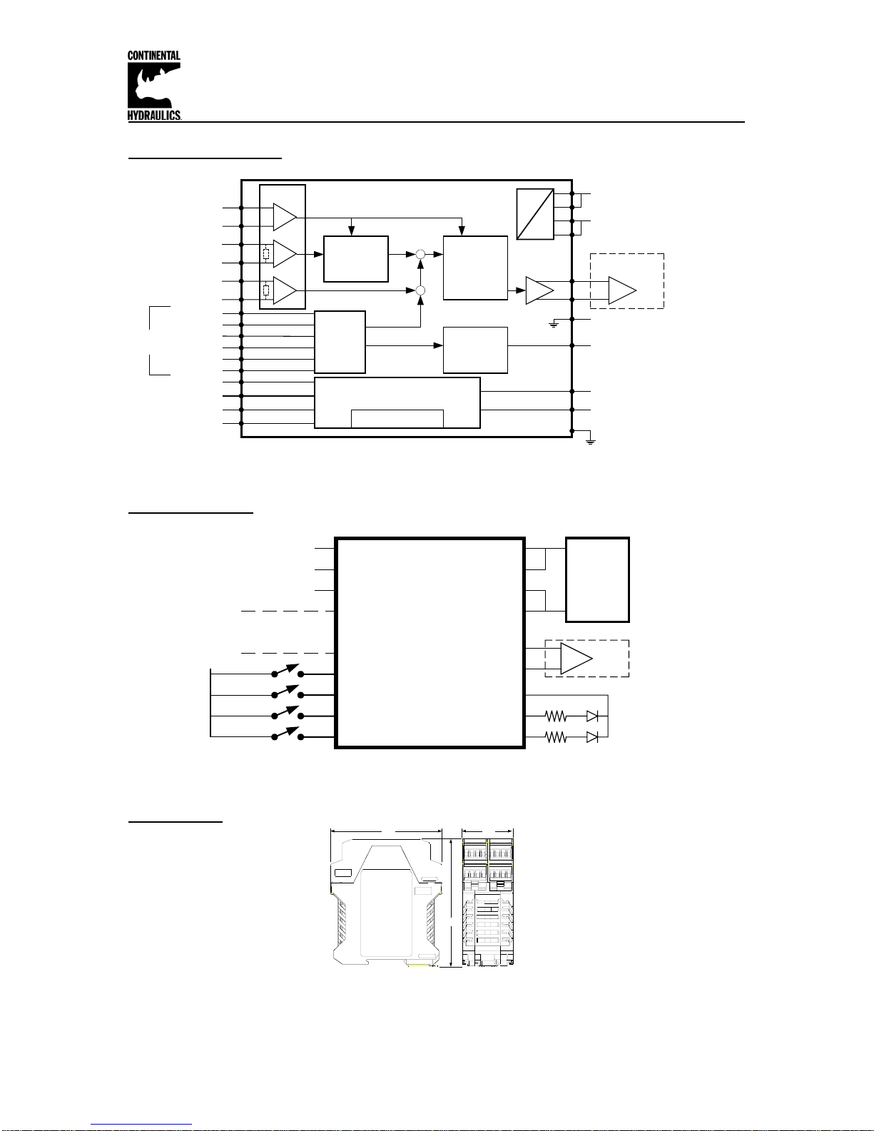
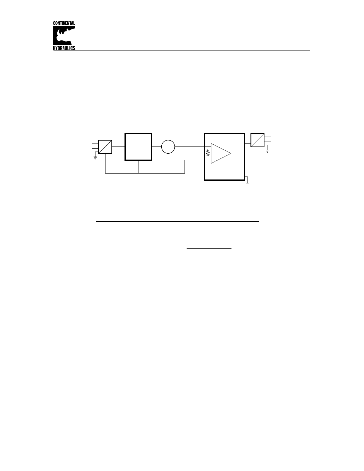
Scaling of analog input:
This module has a native analog voltage input range of 0 to +10v for command and feedback.
These inputs can be scaled and offset with software to allow a wide variety of input voltages. A
few examples are:
0 to +10v, 0 to +5v, +1 to +5v, +0.5 to +4.5v
The AIN:W parameter adjusts command port, and AIN:X parameter adjusts the feedback port.
Each can be independently set for either voltage or current command, and each can be
independently scaled.
Example: AIN:W V will set the command input to voltage. Default range = 0 to +10v
Example: AIN:W C will set the command input to current. Default range = 4 to 20mA
Example: AIN:X V will set the feedback input to voltage. Default range = 0 to +10v
Example: AIN:X C will set the feedback input to current. Default range = 4 to 20mA
Analog voltages or currents are scaled with the following linear equation:
Output = A/B * (Input – C)
“Output” of this scaling equation must always be equal to the module native input range, 0 to
+10v. “Input” can be any voltage within this 10v range.
The ratio of A/B allows for a decimal scaling factor. These two numbers are chosen to provide a
“gain” to the input signal. A and B must be whole numbers. Range is -10000 to 10000.
(Default; A = 1000, B = 1000)
C is an offset, measured as a percentage of range. C has units of 0.01%, and has the range of
–10000 to 10000. (Default; C = 0)
Scaling of voltage inputs:
Example: Typical AIN parameter settings for popular command and feedback voltages:
Command A B C description
0 to +10v 1000 1000 0 100% scale, 0% offset
0 to +10v 1 1 0 100% scale, 0% offset
0 to +10v 10 10 0 100% scale, 0% offset
0 to +5v 10 5 0 200% scale, 0% offset
+1 to +9v 10 8 1000 125% scale, 10% offset
+0.5 to +4.5v 10 4 500 250% scale, 5% offset
0 to 8v 10 8 0 125% scale, 0% offset
Scaling of current inputs:
Example: Typical AIN parameter settings for popular command and feedback currents:
Command A B C description
4 to 20mA 20 16 2000 125% scale, 20% offset
4 to 20mA 1250 1000 2000 125% scale, 20% offset
4 to 20mA 5 4 2000 125% scale, 20% offset
0 to 20mA 20 20 0 100% scale, 0% offset

Continental Hydraulics Installation Manual
Page 11 of 15 CEM-SD-A CHI 1013477 May 2012
Swapping polarity with the POL parameter:
The output drive polarity may be swapped with the POL command.
Valid parameter values are “+” and “-“. (Default = +).
Adjustment of SENS internal monitoring function:
This module has optional input and internal monitoring functions. The module can monitor
command inputs for proper range.
There are three choices for SENS; OFF, ON, and AUTO (default).
OFF disables the internal sensing function.
ON and AUTO enable the internal sensing functions. The difference between ON and AUTO is
how the module handles error correction.
When ON is selected, if the module detects an error, the module will disable.
After the error is corrected, the ENABLE pin must be cycled to reactivate the
module.
When AUTO is selected, if the module detects an error, the module will disable.
When the error is corrected, the module will resume function without cycling
ENABLE.
If the module has been configured to accept current commands, a command value outside of 4 to
20 mA will disable the module, and cause the green READY LED to blink.
HAND+ (jog+) (pin 6) and HAND- (jog-) (pin 5) digital inputs:
HAND:A and HAND:B are digital inputs that are active high.
HAND:A adjusts the speed command to the valve. The valve will move the load in open loop
mode at the rate set by HAND. Once the HAND input is released, the new position command
setpoint is whatever the position was when hand is released. HAND:A and HAND:B have valid
values from –10000 to +10000. Units are 0.01%. Default for HAND:A is 3333(+1/3), and
HAND:B is –3333(-1/3).
START(RUN) takes priority over HAND.
EOUT parameter:
EOUT sets a default module output value. When ENABLE (pin 8) has been removed, or the
module has become disabled, the output may be set to a value other than zero. This allows the
machine to slowly extend or retract in the case of loss of electro hydraulic control.
Parameter valid –10,000 thru +10,000. Default is 0. Units of 0.01%

Continental Hydraulics Installation Manual
Page 12 of 15 CEM-SD-A CHI 1013477 May 2012
OFFSET parameter:
OFFSET is a fixed adjust to the output. OFFSET valid values are from –4000 to +4000. Units
are 0.01%. Default is 0.
ENABLE (pin 8) digital input:
ENABLE is a digital input that is active high.
When the ENABLE input is low, there is no output to the valve. Command input and feedback
input values are ignored. All other inputs are also ignored.
To active the HAND function, ENABLE must be held active.
If ENABLE is removed during an active motion profile, the output to the valve is instantly brought
to zero.
START (RUN) (pin 7) digital input:
START (RUN) is a digital input that is active high.
Bringing pin 7 high (while holding pin 8(ENABLE) high), forces the module into closed loop
position control mode.
If RUN is removed during an active motion profile, the output to the valve is ramped to zero
during the preset emergency stop distance parameter (D:S). Units of D:S are mm. Default is 10.
InPOS pin 2 digital output:
InPOS (pin 2) is a digital output that is normally low. When the module is in active control, this
output will be high, as long as the controller is within INPOS parameter. INPOS parameter is
valid from 2 to 10000. Units are micrometer. Default is 1000.
When the control module is active, but outside of the INPOS parameter, the InPOS output will go
low. The module continues to actively control the valve.

Continental Hydraulics Installation Manual
Page 13 of 15 CEM-SD-A CHI 1013477 May 2012
READY pin 1 digital output:
The READY digital output reports the system status.
Pin 5 will be held “high” (on) when ENABLE is connected, and there are no system errors.
Pin 5 will be pulled “low” (off) under the following conditions:
1. When ENABLE is removed
2. When SENS is turned on and the input is outside the 4 to 20mA range
3. When other internal errors are present
LED function:
Green (Ready) Steady on System OK
Blinking 4 to 20mA current input command is out of range
Blinking internal error sensed
Yellow (Status) Steady on Load is within InPOS tolerance
Off Load is not within InPOS tolerance

Continental Hydraulics Installation Manual
Page 14 of 15 CEM-SD-A CHI 1013477 May 2012
Interface for Digital SSI feedback:
The SSI digital feedback sensor communicates with the CEM-SD over a RS-422 serial interface.
Power and ground to supply the sensor are also provided.
Pin 25 + Clock
Pin 26 -Clock
Pin 27 + Data
Pin 28 -Data
Pin 31 24v power
Pin 32 0v ground
Analog output of digital feedback signal (pin 17):
The SSI digital feedback sensor values are available as an analog voltage. Digital position of 0 to
100% is available as an analog voltage of 0 to +10v. (5mA max)
Parameter adjustments for SSI digital feedback:
INPX parameter:
This parameter allows the selection of either analog feedback input (pins 14/11), or the digital SSI
feedback. Valid parameters are ANA or SSI. Default is ANA.
SSI:OFFSET parameter:
The digital feedback signal may be calibrated with a fixed offset. Valid parameter range is
+1,000,000 to –1,000,000. Units are micrometers.
SSI:POL parameter:
Digital SSI feedback polarity may be swapped from “+” to “-“. Default is “+”.
SSI:RES parameter:
Digital SSI feedback resolution is defined with this parameter. Valid range is 100 to 10000.
Default is 500. Units are nanometers (0.01micrometers).
Example: parameter 100 = 1 micrometer sensor resolution
SSI:BITS parameter:
The number of data bits in the digital sensor serial data stream is defined with this parameter.
Valid values are 8 to 31. Default is 24.

Continental Hydraulics Installation Manual
Page 15 of 15 CEM-SD-A CHI 1013477 May 2012
Parameter adjustments for SSI digital feedback: (continued)
SSI:CODE parameter:
Digital SSI feedback sensors data may be defined as either GRAY scale, or BINary. Default is
GRAY.
Parameter monitoring using software:
The following parameters may be monitored in real time using Windows configuration software.
Parameter Description Unit
WA Command mm
W Command after scale & ramp mm
X Feedback after scaling mm
XD Command – Feedback mm
V Velocity command 0.01%
U Output 0.01%
Table of contents
Other Continental Hydraulics Control Unit manuals

Continental Hydraulics
Continental Hydraulics CEM-MS-A User manual

Continental Hydraulics
Continental Hydraulics CEM-SA-B User manual

Continental Hydraulics
Continental Hydraulics VSD08M User manual

Continental Hydraulics
Continental Hydraulics A Design Series User manual

Continental Hydraulics
Continental Hydraulics A Series User manual

Continental Hydraulics
Continental Hydraulics CEM-BPS-B User manual