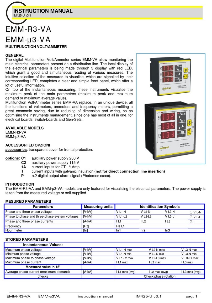
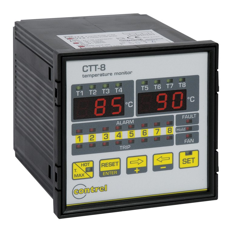
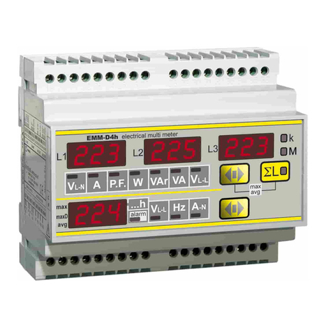
Contrel EMC Series User manual

EMC protocol communication instruction manual IM154-U v0.94 pag. 1 / 12
INSTRUCTION MANUAL
IM154-U v0.94
EMC series ELECTRICAL MULTIFUNCTION METER COMMUNICATION PROTOCOL
EMC h series MULTIMETERS MODBUS-RTU COMMUNICATION PROTOCOL
MODBUS PROTOCOL
Modbus is a master-slave communication protocol able to support up to 247 slaves organized as a bus or as a star
network;
The physical link layer can be RS232 for a point to point connection or RS485 for a network.
The communication is half-duplex.
The network messages can be Query-Response or Broadcast type.
The Query-Response command is transmitted from the Master to an established Slave and generally it is followed by an
answering message.
The Broadcast command is transmitted from the Master to all Slaves and is never followed by an answer.
MODBUS use two modes for transmission.
A) ASCII Mode: uses a limited character set as a whole for the communication.
B) RTU Mode: binary, with time frame synchronization, faster than the ASCII Mode, uses half so long data block than
the ASCII Mode.
EMC analyzers employ RTU mode.
GENERIC MESSAGE STRUCTURE:
START
OF
FRAME
ADDRESS
FIELD FUNCTION
CODE DATA
FIELD ERROR
CHECK
END
OF
FRAME
START OF FRAME = Starting message marker
ADDRESS FIELD = Includes device address in which you need to communicate in Query-Response mode. In case
the message is a Broadcast type it includes 00.
FUNCTION CODE = Includes the operation code that you need to perform.
DATA FIELD = Includes the data field.
ERROR CHECK = Field for the error correction code.
END OF FRAME = End message marker.
Mode RTU communication frame structure:
START OF FRAME = silence on line for time >=4 characters
ADDRES FIELD = 1 character
FUNCTION CODE = 1 character
DATA FIELD = N characters
ERROR CHECK = 16 bit CRC
END OF FRAME = silence on line for time >=4 characters
Wait time for response :
- typical : 150 mS
- worst case : 300 mS.

EMC protocol communication instruction manual IM154-U v0.94 pag. 2 / 12
CRC GENERATION
Example of the CRC-16 generation with "C" language:
static unsigned char auchCRCHi [ ] = {
0x00, 0xC1, 0x81, 0x40, 0x01, 0xC0, 0x80, 0x41, 0x01, 0xC0, 0x80, 0x41, 0x00, 0xC1, 0x81,
0x40, 0x01, 0xC0, 0x80, 0x41, 0x00, 0xC1, 0x81, 0x40, 0x00, 0xC1, 0x81, 0x40, 0x01, 0xC0,
0x80, 0x41, 0x01, 0xC0, 0x80, 0x41, 0x00, 0xC1, 0x81, 0x40, 0x00, 0xC1, 0x81, 0x40, 0x01,
0xC0, 0x80, 0x41, 0x00, 0xC1, 0x81, 0x40, 0x01, 0xC0, 0x80, 0x41, 0x01, 0xC0, 0x80, 0x41,
0x00, 0xC1, 0x81, 0x40, 0x01, 0xC0, 0x80, 0x41, 0x00, 0xC1, 0x81, 0x40, 0x00, 0xC1, 0x81,
0x40, 0x01, 0xC0, 0x80, 0x41, 0x00, 0xC1, 0x81, 0x40, 0x01, 0xC0, 0x80, 0x41, 0x01, 0xC0,
0x80, 0x41, 0x00, 0xC1, 0x81, 0x40, 0x00, 0xC1, 0x81, 0x40, 0x01, 0xC0, 0x80, 0x41, 0x01,
0xC0, 0x80, 0x41, 0x00, 0xC1, 0x81, 0x40, 0x01, 0xC0, 0x80, 0x41, 0x00, 0xC1, 0x81, 0x40,
0x00, 0xC1, 0x81, 0x40, 0x01, 0xC0, 0x80, 0x41, 0x01, 0xC0, 0x80, 0x41, 0x00, 0xC1, 0x81,
0x40, 0x01, 0xC1, 0x81, 0x40, 0x01, 0xC0, 0x80, 0x41, 0x00, 0xC1, 0x81, 0x40, 0x01, 0xC0,
0x80, 0x41, 0x01, 0xC0, 0x80, 0x41, 0x00, 0xC1, 0x81, 0x40, 0x00, 0xC1, 0x81, 0x40, 0x01,
0xC0, 0x80, 0x41, 0x01, 0xC0, 0x80, 0x41, 0x00, 0xC1, 0x81, 0x40, 0x01, 0xC0, 0x80, 0x41,
0x00, 0xC1, 0x81, 0x40, 0x00, 0xC1, 0x81, 0x40, 0x01, 0xC0, 0x80, 0x41, 0x00, 0xC1, 0x81,
0x40, 0x01, 0xC0, 0x80, 0x41, 0x01, 0xC0, 0x80, 0x41, 0x00, 0xC1 0x81, 0x40, 0x01, 0xC0,
0x80, 0x41, 0x00, 0xC1, 0x81, 0x40, 0x00, 0xC1, 0x81, 0x40, 0x01, 0xC0, 0x80, 0x41, 0x01,
0xC0, 0x80, 0x41, 0x00, 0xC1, 0x81, 0x40, 0x00, 0xC1, 0x81, 0x40, 0x01, 0xC0, 0x80, 0x41,
0x00, 0xC1, 0x81, 0x40, 0x01, 0xC0, 0x80, 0x41, 0x01, 0xC0, 0x80, 0x41, 0x00, 0xC1, 0x81,
0x40
} ;
static unsigned char auchCRCLo [ ] = {
0x00, 0xC0, 0xC1, 0x01, 0xC3, 0x03, 0x02, 0xC2, 0xC6, 0x06, 0x07, 0xC7, 0x05, 0xC5, 0xC4,
0x04, 0xCC, 0x0C, 0x0D, 0xCD, 0x0F, 0xCF, 0xCE, 0x0E, 0x0A, 0xCA, 0xCB, 0x0B, 0xC9, 0x09,
0x08, 0xC8, 0xD8, 0x18, 0x19, 0xD9, 0x1B, 0xDB, 0xDA, 0x1A, 0x1E, 0xDE, 0xDF, 0x1F, 0xDD,
0x1D, 0x1C, 0xDC, 0x14, 0xD4, 0xD5, 0x15, 0xD7, 0x17, 0x16, 0xD6, 0xD2, 0x12, 0x13, 0xD3,
0x11, 0xD1, 0xD0, 0x10, 0xF0, 0x30, 0x31, 0xF1, 0x33, 0xF3, 0xF2, 0x32, 0x36, 0xF6, 0xF7,
0x37, 0xF5, 0x35, 0x34, 0xF4, 0x3C, 0xFC, 0xFD, 0x3D, 0xFF, 0x3F, 0x3E, 0xFE, 0xFA, 0x3A,
0x3B, 0xFB, 0x39, 0xF9, 0xF8, 0x38, 0x28, 0xE8, 0xE9, 0x29, 0xEB, 0x2B, 0x2A 0xEA, 0xEE,
0x2E, 0x2F, 0xEF, 0x2D, 0xED, 0xEC, 0X2C, 0xE4, 0x24, 0x25, 0xE5, 0x27, 0xE7, 0xE6, 0x26,
0x22, 0xE2, 0xE3, 0x23, 0xE1, 0x21, 0x20, 0xE0, 0xA0, 0x60, 0x61, 0xA1, 0x63, 0xA3, 0xA2,
0x62, 0x66, 0xA6, 0xA7, 0x67, 0xA5, 0x65, 0x64, 0xA4, 0x6C, 0xAC, 0xAD, 0x6D, 0xAF, 0x6F,
0x6E, 0xAE, 0xAA, 0x6A, 0x6B, 0xAB, 0x69, 0xA9, 0xA8, 0x68, 0x78, 0xB8, 0xB9, 0x79, 0xBB,
0x7B, 0x7A, 0xBA, 0xBE, 0x7E, 0x7F, 0xBF, 0x7D, 0xBD, 0xBC, 0x7C, 0xB4, 0x74, 0x75, 0xB5,
0x77, 0xB7, 0xB6, 0x76, 0x72, 0xB2, 0xB3, 0x73, 0xB1, 0x71, 0x70, 0xB0, 0x50, 0x90, 0x91,
0x51, 0x93, 0x53, 0x52, 0x92, 0x96, 0x56, 0x57, 0x97, 0x55, 0x95, 0x94, 0x54, 0x9C, 0x5C,
0x5D, 0x9D, 0x5F, 0x9F, 0x9E, 0x5E, 0x5A, 0x9A, 0x9B, 0x5B, 0x99, 0x59, 0x58, 0x98, 0x88,
0x48, 0x49, 0x89, 0x4B, 0x8B, 0x8A, 0x4A, 0x4E, 0x8E, 0x8F, 0x4F, 0x8D, 0x4D, 0x4C, 0x8C,
0x44, 0x84, 0x85, 0x45, 0x87, 0x47, 0x46, 0x86, 0x82, 0x42, 0x43, 0x83, 0x41, 0x81, 0x80,
0x40
}
unsigned short CRC16 (ptMsg, usDataLen)
unsigned char *ptMsg; / * message to calculate CRC upon * /
unsigned short usDataLen; / * number of bytes in message * /
{
unsigned char uchCRCHi = 0xFF; / * CRC high byte * /
unsigned char uchCRCLo =0xFF; / * CRC low byte * /
unsigned uIndex;
while (usDataLen--) / * pass through message buffer * /
{
uIndex = uchCRCHi ^*ptMsg++; /.* calculate the CRC * /
uchCRCHi = uchCRCLo ^auchCRCHi [uIndex ];
uchCRCLo = auchCRCLo [uIndex ]
}
return (uchCRCHi «8 |uchCRCLo ) ;
}
Note: The ”Error Check (CRC)” field must be computed referring to the characters from the first of ADDR to the
last of DATA inclusive.
EMC protocol communication instruction manual IM154-U v0.94 pag. 3 / 12
READING OF THE REGISTERS ( Function Code $ 03)
Reads the binary contents of holding registers ( 2X references) in the slave.
Broadcast is not supported.
The Query message specified the starting register and quantity of register to be read.
QUERY:
START
OF
FRAME
ADDRESS
FIELD FUNCTION
CODE START
ADDRESS No. OF
REGISTERS ERROR
CHECK
END
OF
FRAME
START OF FRAME = Starting message marker.
ADDRESS FIELD = EMC device address (01...F7 HEX) (1 byte).
FUNCTION CODE = Operation code (03 HEX) (1 byte).
START ADDRESS = First register address to be read (2 byte).
No. OF REGISTERS = Number of registers (max 32) to be read (4 bytes for 1 measure value).
ERROR CHECK = Check sum.
END OF FRAME = End message marker.
WARNING:
It is possible to read more than one variable at the same time (max 16) only if their addresses are consecutive and the
variables on the same line cannot be divided.
The register data in the response message are packet as two bytes per register, with the binary contents right justified
within each byte.
For each register, the first byte contains the high order bits and the second contains the low order bits.
RESPONSE:
START
OF
FRAME
ADDRESS
FIELD FUNCTION
CODE No. OF
BYTES D0, D1, …, Dn ERROR
CHECK
END
OF
FRAME
START OF FRAME = Starting message marker.
ADDRESS FIELD = EMC device address (01...F7 HEX) (1byte).
FUNCTION CODE = Operation code ( 03 HEX) (1 Byte).
No. OF SEND BYTES= Number of data bytes ( 00...?? HEX) (1 byte). 1 register requires 2 data bytes.
D0, D1, .., Dn = data bytes ( 00...?? HEX) (Nr. of register x 2 = n. byte).
ERROR CHECK = Check sum.
END OF FRAME = End message marker .
See the TABLE OF EMC REGISTERS and the EXAMPLE.

EMC protocol communication instruction manual IM154-U v0.94 pag. 4 / 12
SETUP OF THE EMC PARAMETERS (Function Code $ 10 )
Write values into a sequence of holding registers (2X references).
WARNING: It is possible to write more than one variable at the same time only if their addresses are consecutive and the
variables on the same line cannot be divided. (max of 4 consecutive register on the same message).
QUERY:
START
OF
FRAME
ADDRESS
FIELD FUNCTION
CODE START
ADDRESS No. OF
REGISTERS No. OF
BYTES D0, D1, …, Dn ERROR
CHECK
END
OF
FRAME
START OF FRAME = Starting message marker.
ADDRESS FIELD = EMC device address ( 01...F7 HEX) (1 byte).
FUNCTION CODE = Operation code ( 10 HEX) (1 byte).
START ADDRESS = First register address to be written (2 byte).
No. OF REGISTER = Number of registers to be written (1 to 4,...) (2 byte).
No. OF BYTES = Number of data bytes (HEX) (1 byte): 1register requires 2 data bytes.
D0,D1,..,Dn = Data bytes ( 00...? HEX) (1 byte) (Nr. of register x 2 = n. byte).
ERROR CHECK = Check sum.
END OF FRAME = End message marker.
The normal response returns the slave address, function code, starting address and quantity of register preset.
RESPONSE:
START
OF
FRAME
ADDRESS
FIELD FUNCTION
CODE START
ADDRESS No. OF
REGISTERS ERROR
CHECK
END
OF
FRAME
START OF FRAME = Starting message marker.
ADDRESS FIELD = EMC device address ( 01...F7 HEX) (1 byte).
FUNCTION CODE = Operation code (10 HEX) (1 byte).
START ADDRESS = First register address to be written (2 byte).
No. OF REGISTER = Number of registers to be written (2 byte).
ERROR CHECK = Check sum.
END OF FRAME = End message marker.
See the TABLE OF EMC REGISTERS and the EXAMPLE.

EMC protocol communication instruction manual IM154-U v0.94 pag. 5 / 12
DIAGNOSTIC (Function Code $ 08)
This function provides a test for checking the communication system.
Broadcast is not supported.
The instrument’s protocol has only the sub-function 0 of the diagnostics sub-functions set of the standard modbus
protocol.
The Query and the Response messages are the following:
QUERY:
START
OF
FRAME
ADDRESS
FIELD FUNCTION
CODE SUB
FUNCTION DATA ERROR
CHECK
END
OF
FRAME
START OF FRAME = Starting message marker.
ADDRESS FIELD = EMC device address (01...F7 HEX) (1 byte).
FUNCTION CODE = Operation code ( 08 HEX) (1 byte).
SUB FUNCTION = Sub-function 0 (00 00 hex) (2 byte).
DATA = Max 10 data bytes.
ERROR CHECK = Check sum.
END OF FRAME = End message marker.
RESPONSE:
The response must be the loopback of the same data.
START
OF
FRAME
ADDRESS
FIELD FUNCTION
CODE SUB
FUNCTION DATA ERROR
CHECK
END
OF
FRAME
START OF FRAME = Starting message marker.
ADDRESS FIELD = EMC device address (01...F7 HEX) (1 byte).
FUNCTION CODE = Operation code ( 08 HEX) (1 byte).
SUB FUNCTION = Sub-function 0 (00 00 hex) (2 byte).
DATA = Data bytes.
ERROR CHECK = Check sum.
END OF FRAME = End message marker.
DIAGNOSTIC EXAMPLE
QUERY RESPONSE
Field Name Example (Hex) Field Name Example (Hex)
Slave Address 01 Slave Address 01
Function Code 08 Function Code 08
Sub-function Hi 00 Sub-function Hi 00
Sub-function Lo 00 Sub-function Lo 00
Data Hi F1 Data Hi F1
Data Lo A7 Data Lo A7
Error Check (CRC) ?? Error Check (CRC) ??
?? ??

EMC protocol communication instruction manual IM154-U v0.94 pag. 6 / 12
REPORT SLAVE ID (Function Code $ 11)
This function returns the type of the instrument and the current status of the slave run indicator.
Broadcast is not supported.
The Query and the Response messages are the following:
QUERY:
START
OF
FRAME
ADDRESS
FIELD FUNCTION
CODE ERROR
CHECK
END
OF
FRAME
START OF FRAME = Starting message marker.
ADDRESS FIELD = EMC device address (01...F7 HEX) (1 byte).
FUNCTION CODE = Operation code ( 11 HEX) (1 byte).
ERROR CHECK = Check sum.
END OF FRAME = End message marker.
RESPONSE:
START
OF
FRAME
ADDRESS
FIELD FUNCTION
CODE BYTE
COUNT SLAVE
ID
RUN
INDICATOR
STATUS DATA ERROR
CHECK
END
OF
FRAME
START OF FRAME = Starting message marker.
ADDRESS FIELD = EMC device address (01...F7 HEX) (1 byte).
FUNCTION CODE = Operation code (11 HEX) (1 byte).
BYTE COUNT = Number of data bytes (16 HEX) (1 byte).
SLAVE ID = Slave ID identifier (50 HEX) (1 byte).
RUN INDICATOR STATUS = Run indicator status (FF HEX) (1 byte).
DATA = Data bytes.
ERROR CHECK = Check sum.
END OF FRAME = End message marker.
The normal response has the slave ID identifier (50 HEX) and the run indicator status (FF HEX) plus 20 data bytes (byte
count is 22, 16 Hex). Last four data bytes carry firmware version (bytes 19 ,20 ) and bit-mapped options installed on EMC
(bytes 17,18).
Byte 17 mapped bit (Value = 1: -> option installed):
Bit 0 Pulse output (Energy)
Bit 1 Neutral Current Input
Bit 5 Digital Output for Alarm function.
Bit 7 Double tariff function (Time Bands)
Bit 2,3,4,6 No meaning
Byte 18 mapped bit (Value = 1: -> option installed):
Bit 1 Analog output
Other bits: No meaning
REPORT SLAVE ID EXAMPLE
QUERY RESPONSE
Field Name Example (Hex) Field Name Example ( Hex)
Slave Address 01 Slave Address 01
Function Code 11 Function Code 11
Error Check (CRC) ?? Byte count 02
?? Slave ID 50
Run indicator status FF
Data 20 data bytes
Error Check (CRC) ??
??

EMC protocol communication instruction manual IM154-U v0.94 pag. 7 / 12
ERROR MESSAGE FROM SLAVE TO MASTER
When a slave device receives a not valid query, it does transmit an error message.
RESPONSE:
START
OF
FRAME
ADDRESS
FIELD FUNCTION
CODE ERROR
CODE ERROR
CHECK
END
OF
FRAME
START OF FRAME = Starting message marker.
ADDRESS FIELD = EMC device address ( 01...F7 HEX) (1 byte).
FUNCTION CODE = Operation code with bit 7 high (1 byte).
ERROR CODE = Message containing communication failure (1 byte).
ERROR CHECK = Check sum.
END OF FRAME = End message marker.
ERROR EXAMPLE
QUERY RESPONSE
Field Name Example (Hex) Field Name Example (Hex)
Slave Address 01 Slave Address 01
Function Code 03 Function Code 83 (1)
Starting Address Hi 00 Error Code 02 (2)
Starting Address Lo 00 Error Check (CRC) ??
Number Of Word Hi 00 ??
Number Of Word Lo 05
Error Check (CRC) ?? (1): Function Code transmitted by master with bit 7 high.
?? (2): Error type:
01 = Illegal Function
02 = Illegal data address
03 = Illegal data value

EMC protocol communication instruction manual IM154-U v0.94 pag. 8 / 12
TABLE OF EMC REGISTERS
The following table shown all the EMC registers. All registers are 16-bit integer type (signed or unsigned).
MEASURED VALUES (Function code $ 03)
Register HEX Word Description M. U. Type
$1000 2 3-PHASE SYSTEM VOLTAGE [V] (Unsigned)
$1002 2 PHASE VOLTAGE L1-N [V] (Unsigned)
$1004 2 PHASE VOLTAGE L2-N [V] (Unsigned)
$1006 2 PHASE VOLTAGE L3-N [V] (Unsigned)
$1008 2LINE TO LINE VOLTAGE L1-2 [V] (Unsigned)
$100A 2LINE TO LINE VOLTAGE L2-3 [V] (Unsigned)
$100C 2LINE TO LINE VOLTAGE L3-1 [V] (Unsigned)
$100E 23-PHASE SYSTEM CURRENT [mA] (Unsigned)
$1010 2LINE CURRENT L1[mA] (Unsigned)
$1012 2LINE CURRENT L2[mA] (Unsigned)
$1014 2LINE CURRENT L3[mA] (Unsigned)
$1016 2 3-PHASE SYSTEM POWER FACTOR [-] (Signed)
$1018 2 POWER FACTOR L1[-] (Signed)
$101A 2 POWER FACTOR L2[-] (Signed)
$101C 2 POWER FACTOR L3[-] (Signed)
$101E 2
3-PHASE SYSTEM COS[-] (Signed)
$1020 2
PHASE COS1[-] (Signed)
$1022 2
PHASE COS2[-] (Signed)
$1024 2
PHASE COS3[-] (Signed)
$1026 2 3-PHASE SYSTEM APPARENT POWER [VA] (Unsigned)
$1028 2 APPARENT POWER L1[VA] (Unsigned)
$102A 2 APPARENT POWER L2[VA] (Unsigned)
$102C 2 APPARENT POWER L3[VA] (Unsigned)
$102E 2 3-PHASE SYSTEM ACTIVE POWER [W] (Unsigned)
$1030 2 ACTIVE POWER L1[W] (Unsigned)
$1032 2 ACTIVE POWER L2[W] (Unsigned)
$1034 2 ACTIVE POWER L3[W] (Unsigned)
$1036 2 3-PHASE SYSTEM REACTIVE POWER [VAR(Unsigned)
$1038 2 REACTIVE POWER L1[VAR(Unsigned)
$103A 2 REACTIVE POWER L2[VAR(Unsigned)
$103C 2 REACTIVE POWER L3[VAR(Unsigned)
….
$1046 2 FREQUENCY [mHz] (Unsigned)
$1048 2 NEUTRAL CURRENT [mA] (Unsigned)
….
$1096 2 TEMPERATURE [°C] (Unsigned)
$1098 2 HOURS COUNTER [dh] (Unsigned)
NOTE:
- WHEN THE INSTRUMENT CAN’T MEASURE IT SEND 0000 AS VALUE.
- …. means that there are registers not consecutive

EMC protocol communication instruction manual IM154-U v0.94 pag. 9 / 12
ENERGY COUNTERS
MODBUS DATA REGISTERS FOR ENERGY COUNTERS
Register HEX Word Description M. U. Type
$103E 2 3-PHASE SYS. ACTIVE ENERGY T1 100*Wh(Unsigned)
$1040 2 3-PHASE S. REACTIVE ENERGY T1 [100*VARh
] (Unsigned)
$1042 2 3-PHASE SYS. ACTIVE ENERGY T2 100*Wh(Unsigned)
$1044 2 3-PHASE S. REACTIVE ENERGY T2 [100*VARh
] (Unsigned)
....
$104A 2 3-PHASE S. APPARENT ENERGY T1 [100*VAh] (Unsigned)
$104C 2 3-PHASE S. APPARENT ENERGY T2 [100*VAh] (Unsigned)
NOTE:
The energy counters T1 are TOTAL energy or TIMEBAND 1 depending to the setting of EMC.
The energy counters T2 are PARTIAL energy or TIMEBAND 2 depending to the setting of EMC.
If the EMC doesn’t support the function TOTAL/PARTIAL and TIMEBANDS T1 / T2 the available energy
counters are only T1
VALUES STORED IN EEPROM (Function code $03)
Register HEX Word Description U.M. Type
$1060 2 MAX ISTANT. CURRENT L1 [mA] (Unsigned)
$1062 2 MAX ISTANT. CURRENT L2 [mA] (Unsigned)
$1064 2 MAX ISTANT. CURRENT L3 [mA] (Unsigned)
$1066 2 MAX ISTANT. 3-PHASE ACTIVE POWER [W] (Unsigned)
$1068 2 MAX ISTANT. 3-PHASE APPARENT POWER [VA] (Unsigned)
$106A 2 MAX AVG (max demand) CURRENT L1 [mA] (Unsigned)
$106C 2 MAX AVG (max demand) CURRENT L2 [mA] (Unsigned)
$106E 2 MAX AVG (max demand) CURRENT L3 [mA] (Unsigned)
$1070 2 MAX AVG (max demand) 3-PH. ACTIVE POWER [W] (Unsigned)
$1072 2 MAX ISTANT. VOLTAGE L1 [V] (Unsigned)
$1074 2 MAX ISTANT. VOLTAGE L2 [V] (Unsigned)
$1076 2 MAX ISTANT. VOLTAGE L3 [V] (Unsigned)
$1078 2 MAX ISTANT. 3-PHASE REACTIVE. POWER [VAr] (Unsigned)
$107A 2 MAX AVG (max demand) 3-PH. REACTIVE POWER [VAr] (Unsigned)
$107C 2 MAX AVG (max demand) 3-PH. APPARENT POWER [VA] (Unsigned)
$107E 2 LAST AVERAGE 3-PHASE ACTIVE POWER [W] (Unsigned)
$1080 2 LAST AVERAGE 3-PHASE REACTIVE POWER [VAr] (Unsigned)
$1082 2 LAST AVERAGE 3-PHASE APPARENT POWER [VA] (Unsigned)
$1084 2 MAX ISTANT. CURRENT NEUTRAL [mA] (Unsigned)
$1086 2 MAX AVG (max demand) CURRENT NEUTRAL [mA] (Unsigned)
$1088 2 LAST AVERAGE CURRENT NEUTRAL [mA] (Unsigned)
$108A 2 LAST AVERAGE CURRENT L1 [mA] (Unsigned)
$108C 2 LAST AVERAGE CURRENT L2 [mA] (Unsigned)
$108E 2 LAST AVERAGE CURRENT L3 [mA] (Unsigned)

EMC protocol communication instruction manual IM154-U v0.94 pag. 10 / 12
WRITE EMC PARAMETERS (Function code $10)
RESET
Register HEX Wor
dDescription WRITE Value
MSB word LSB word
$11B0 2 RESET ENERGY COUNTERS $11B0 $55AA
$11B2 2 RESET MAX. ISTANTANEOUS VALUES $11B2 $55AA
$11B4 2 RESET MAX AVG (max demand) VALUES $11B4 $55AA
$11B6 2 RESET ALL VALUES (MAX and counters values) $11B6 $55AA
DIGITAL OUTPUTS MANAGEMENT
Register HEX Word Description Range
$11A8 2 DIGITAL OUTPUT DO1 CONTROL REGISTER
$11A8 DO1 CONTROL:
$0000 = OFF
$0100 = ON
$11A9 ENABLE CODE
$55AA
$11AA 2 DIGITAL OUTPUT DO2 CONTROL REGISTER
$11AA DO2 CONTROL:
$0000 = OFF
$0100 = ON
$11AB ENABLE CODE
$55AA
NOTE:
It is possible to write to these registers only if in the SETUP DO1 (Digital Output 1) or DO2 the digital output is set to
BY_REMOTE
Otherwise attempt to write these register return an ILLEGAL DATA VALUE modbus error (03 code).
Writing registers $11A8-A9 or $11AA-AB MUST BE DONE in a single message giving DO STATE and ENABLE
CODE.
Example:
The follow message set ON the DO1 on EMC address 01 .(Hex byte )
01 10 11 A8 00 02 04 01 00 55 AA CRC16
The follow message set OFF the DO1 and ON the DO2 on EMC address 01 .(Hex byte )
01 10 11 A8 00 04 08 00 00 55 AA 01 00 55 AA CRC16
READ & WRITE EMC SETTINGS (Function code $03 & $10)
Register HEX Word Description Range
$11A0 2 KCT TRANSFORM RATIO IL1-IL2-IL3 1÷2000
$11A2 2 KVT TRANSFORM RATIO * 0.1
1÷4000 (KVT ratio is from 0.1 to 400)
1 = 0.1
… = …
4000 = 400.0
$11A4 2 kWh/kVArh PULSE WEIGHT
1÷4
1 = 0,01 KWh-KVArh / PULSE
2 = 0,1 KWh-KVArh / PULSE
3 = 1 kWh-kVArh / PULSE
4 = 10 kWh-kVArh / PULSE
$11A6 2 KCTN TRANSFORM RATIO I NEUTRAL 1÷2000

EMC protocol communication instruction manual IM154-U v0.94 pag. 11 / 12
READ EMC SETTING AND STATUS (Function code $03)
Register HEX Word Description Range
$109A 1
DIGITAL OUTPUT DO1 SETTINGS.
MSB byte: DO1 function mode
LSB byte: DO1 alarm parameter
MSB BYTE VALUE MEANING:
1 = ACTIVE ENERGY PULSE OUTPUT
2 = 3PHASE ALARM MODE (table A)
3 = MAX/MIN L123 ALARM MODE (table B)
4 = BY_REMOTE CONTROLLED
$109B 1
DIGITAL OUTPUT DO2 SETTINGS
MSB BYTE: DO2 function mode
LSB BYTE: DO2 alarm parameter
MSB BYTE VALUE MEANING:
1 = REACTIVE ENERGY PULSE OUTPUT
2 = 3PHASE ALARM MODE (table A)
3 = MAX/MIN L123 ALARM MODE (table B)
4 = BY_REMOTE CONTROLLED
Table A - 3PHASE ALARM MODE PARAM
INDEX MEASURE DESCRIPTION FOR 3PHASE ALARM MODE
1 3-PHASE SYSTEM LINE TO NEUTRAL VOLTAGE
2 3-PHASE SYSTEM CURRENT
3 NEUTRAL CURRENT
4 3-PHASE SYSTEM POWER FACTOR
5 3-PHASE SYSTEM ACTIVE POWER
6 3-PHASE SYSTEM REACTIVE POWER
7 3-PHASE SYSTEM APPARENT POWER
8 3-PHASE SYSTEM LINE-TO-LINE VOLTAGE
9 FREQUENCY
10 TEMPERATURE
Table B - MAX-MIN ALARM MODE PARAMETER
INDEX MEASURE DESCRIPTION FOR MAX-MIN ALARM MODE
1 MAX-MIN FOR L1-N L2-N L3-N VOLTAGE
2 MAX-MIN FOR L1 L2 L3 CURRENT
3 UNUSED / INVALID
4 MAX-MIN FOR L1 L2 L3 POWER FACTOR
5 MAX-MIN FOR L1 L2 L3 ACTIVE POWER
6 MAX-MIN FOR L1 L2 L3 REACTIVE POWER
7 MAX-MIN FOR L1 L2 L3 APPARENT POWER
8 MAX-MIN FOR L1-L2 L2-L3 L3-L1 VOLTAGE
9 UNUSED / INVALID
10 UNUSED / INVALID
Register HEX Word Description Range
$109C 1 DIGITAL OUTPUT DO1 & DO2 STATUS MSB BYTE : DO1 STATUS
LSB BYTE : DO2 STATUS
$109D 1 DIGITAL INPUT DI STATUS
MSB BYTE : UNUSED/ALWAYS 0
LSB BYTE : DI STATUS
NOTE: when LSB read value is 01 the DI
input it’s not powered, when 0 DI input
is powered
$109E 1
MSB BYTE: SYNC MODE
LSB BYTE: ENERGY MODE
MSB BYTE VALUE MEANINGS
1 = EXTERNAL SYNC
2 = INT SYNC = 50 Hz
3 = INT SYNC = 60 Hz
LSB BYTE VALUE MEANINGS
1 = TIMEBAND MODE
2 = TOTAL / PARTIAL MODE
3 = NORMAL (SINGLE COUNTER)
$109F 1
MSB BYTE: NEUTRAL LINE MODE
LSB BYTE: SINGLE PHASE /
3PHASE MODE
MSB BYTE VALUE MEANINGS
1 = 4-WIRE (WITH NEUTRAL WIRE )
2 = 3-WIRE
LSB BYTE VALUE MEANINGS
1 = 3PHASE UNBALANCED
2 = 3PHASE BALANCED
3 = SINGLE PHASE

EMC protocol communication instruction manual IM154-U v0.94 pag. 12 / 12
READING EXAMPLE
This is an example of transmitted data to EMC at address 01, requesting 16 variables, as follows:
Register HEX Word Description Range Type
$101E 2 3-PHASE SYSTEM POWER FACTOR [-] (Signed)
$1020 2 POWER FACTOR L1 [-] (Signed)
$1022 2 POWER FACTOR L2 [-] (Signed)
$1024 2 POWER FACTOR L3 [-] (Signed)
$1026 2 3-PHASE SYSTEM APPARENT POWER [VA] (Unsigned)
$1028 2 APPARENT POWER L1[VA] (Unsigned)
$102A 2 APPARENT POWER L2[VA] (Unsigned)
$102C 2 APPARENT POWER L3[VA] (Unsigned)
$102E 2 3-PHASE SYSTEM ACTIVE POWER [W] (Unsigned)
$1030 2 ACTIVE POWER L1[W] (Unsigned)
$1032 2 ACTIVE POWER L2[W] (Unsigned)
$1034 2 ACTIVE POWER L3[W] (Unsigned)
$1036 2 3-PHASE SYSTEM REACTIVE POWER [VAR(Unsigned)
$1038 2 REACTIVE POWER L1[VAR(Unsigned)
$103A 2 REACTIVE POWER L2[VAR(Unsigned)
$103C 2 REACTIVE POWER L3[VAR(Unsigned)
EXAMPLE
Stream data send to EMC (H suffix mean hex data format):
01H EMC address
03H Read function
10H Address of 1st register requested (101EH)
1EH
00H Nr of Register requested (2 registers for each variable =32 registers = 0020H)
20H
20H CRC
D4H CRC
Response from EMC:
01H EMC address
03H Read function
40H Nr. of send bytes
… Follow 64 bytes of data
…
…
If all data is zero (00) the CRC is the following
05H CRC
11H CRC
TROUBLESHOOTING
If response from EMC doesn’t happen:
- check connection from EMC and RS232/RS485 converter ;
- check if data outgoing from the RS232 serial port of the PC come in the RS232/485 converter
- try to increase the wait time for response ( 300 mS is good);
- check if the transmitted data stream is EXACTLY as in example, monitoring the data on the RS485 serial line with a
terminal (i.e. Hyperterminal or other emulator);
- if the RS232/485 converter is not our model EMI-1, be sure the turnaround-time is set in range 1 to 2 mS
elettronica srl
Contrel elettronica srl - 26900 LODI - ITALY - via S. Fereolo, 9
Tel. +39 0371 30207/30761/35386 Fax. +39 0371 32819 E-mail: contrel
@contrel.it
www.contrel.it
ISO 9001:2000
CERTIFICATE
N.9105.C035
Table of contents
Other Contrel Measuring Instrument manuals

Contrel
Contrel EMA-D6 User manual

Contrel
Contrel EMA-90N User manual

Contrel
Contrel EMM-m3-VA User manual

Contrel
Contrel EMA-D9 User manual

Contrel
Contrel EMA90 User manual

Contrel
Contrel EMA11 User manual

Contrel
Contrel CTT8 User manual

Contrel
Contrel CTT8 User manual

Contrel
Contrel RI-SM User manual

Contrel
Contrel EMM-D4h User manual
Popular Measuring Instrument manuals by other brands

METER GROUP
METER GROUP AquaLab 4TE DUO quick start

AND
AND AD-4532B instruction manual

Endress+Hauser
Endress+Hauser Proline t-mass B 150 Brief operating instructions

ATAGO
ATAGO PAL-91S instruction manual

ACR Electronics
ACR Electronics Vecta 3 Product support manual

MICRODOS
MICRODOS MP2-HT PULSE Programming instructions