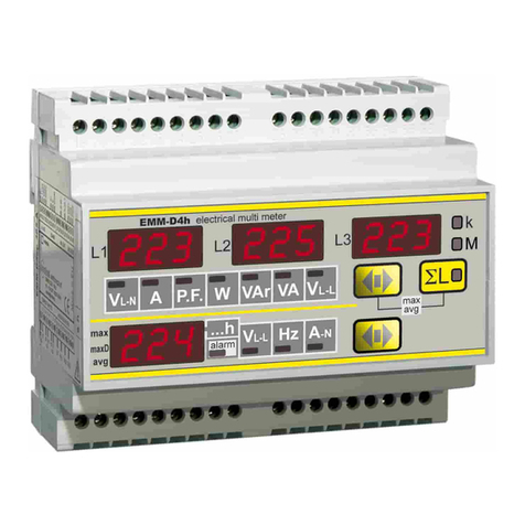
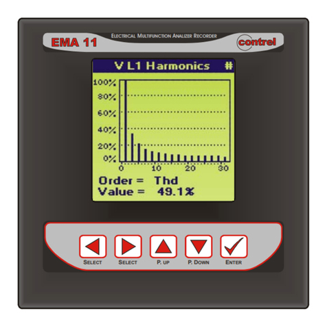
Contrel EMA-90N User manual

EMA‐90N UserManual IM128‐Uv0.74 Pag.1/32
EMA-90N
Electrical Measurement Analyzer
User Manual
IM128-U v0.74

EMA‐90N UserManual IM128‐Uv0.74 Pag.2/32
Index
Description................................................................................................................................................................................................................3
Installation.................................................................................................................................................................................................................4
Auxiliarypowersupply..........................................................................................................................................................................................4
VoltageInputs.......................................................................................................................................................................................................4
CurrentInputs.......................................................................................................................................................................................................4
DigitalInputs/Outputs.........................................................................................................................................................................................8
Serial(RS‐485).......................................................................................................................................................................................................8
Profibus.................................................................................................................................................................................................................8
Ethernet................................................................................................................................................................................................................8
M‐Bus....................................................................................................................................................................................................................8
Keysfunctionality......................................................................................................................................................................................................9
Menu.......................................................................................................................................................................................................................10
Visualizationandmeasures.....................................................................................................................................................................................11
Setup.......................................................................................................................................................................................................................12
General................................................................................................................................................................................................................12
Measure..............................................................................................................................................................................................................13
EnergiesandCounters........................................................................................................................................................................................16
Userpages...........................................................................................................................................................................................................18
Communication...................................................................................................................................................................................................19
I/O.......................................................................................................................................................................................................................21
Setpoint...............................................................................................................................................................................................................23
Log.......................................................................................................................................................................................................................26
Math....................................................................................................................................................................................................................27
Dimensions..............................................................................................................................................................................................................29
Connections.............................................................................................................................................................................................................29
Technicalfeatures...................................................................................................................................................................................................30
Information in this document is subject to change without notice and does not represent a commitment on the part of Contrel Elettronica Srl.
This documentation is consigned to the customer to enable the correct and safe operation of the instrument; any other use of documentation is strictly
prohibited.
The information contained herein is the property of Contrel Elettronica Srl, and by law, no part of it may be reproduced, transcribed, stored in any retrieval
system, or translated into any language by means (even for internal purposes by the customer) without the express written permission of Contrel Elettronica Srl.
In addition, no part of this manual may be transmitted in any form by any means, including photocopying and recording, for any purposes, without the express
written permission of Contrel Elettronica Srl.
In case of Copyright violation the customer is directly responsible.
TERMS OF WARRANTY
The warranty is valid for the period of 24 months after material receipt.
The warranty covers free repair or replacement of equipment parts, which are recognized as faulty due to manufacturing defects.
Warranty does not cover those parts which results defective due to misuse or improper use, incorrect installation or maintenance, operation by unauthorized
personnel, damage during transportation, or which in any case do not show manufacturing defects of the equipment.
Not included in the warranty terms are technical interventions regarding equipment installation to electrical systems.
The manufacturer declines any responsibility for eventual injury or damage to persons, animals or things as result of failure to follow the instructions in the user
manual or caused by improper use of equipment.
The expenses of transport as well as the relative risks of same both to and from the place of repair, will be the sole responsibility of the user.
This warranty expires after the date of purchase and any assistance required after said date including spare parts, labour, transport of personnel and material
will be charged to the user following the tariffs in force for Technical Assistance Service at the time of such requested service.
In any case the replacement of the equipment as well as the extension of warranty after such breakdown is excluded.

EMA‐90N UserManual IM128‐Uv0.74 Pag.3/32
Description
The EMA (Electrical Measurement Analyzer) has advanced analysis functions that allow the measurement of the main electrical parameters: voltage, current,
frequency, power factor, crest factor, active and reactive power, active and reactive energy. The instrument allows the measurement and analysis in real time of
electrical parameters, also verifying the quality of the energy thanks to THD measurement. Bidirectional metering of energy allows both production and
consumption of energy to be monitored with a single device. All information monitored by the analyzer can be transmitted to remote locations through
communication interfaces RS485, Ethernet, Profibus DP e MBUS.
Interaction with the control and supervision systems is possible using inputs and outputs, all programmable. EMA reads and displays the energy values
measured in other energy meters connected to the network. This is achieved thanks to digital inputs, which are able to acquire the impulses generated by the
counters. In this case, EMA acts as a data concentrator. It not only collects information from the electricity meters but also from the water, gas meters or other.
EMA allows a complete, in-depth analysis of the network quality thanks to the measurement of the harmonic distortion (63th order) of the voltage and current
signals (also for the 4th current channel).
Configuration
STANDARD
A
vailable options
Hardware
Format 96x96 96x96 RIN
A
Supply 90÷250
Vac/dc
20÷60
Vac/dc
Current
inputs 1A & 5A(1)
1A & 5
A
+
Neutral(1)
1A & 5A(2) Rogowski(3)
Rogowski
+
Neutral(3)
TTA 50A(4)
I/O 2 DO 4 DO
4 DI
6 DO
2 DI 8 DO 4 DO
2 AO
4 DO
4 AO
8 DI
2 DO(5) 4 AI 2 PT100 2 AI
1 PT100
I/O type DO
photo-mos
DO: photo-mos
DI: 24 Vac/dc
DO: photo-mos
DI: 48 Vac/dc
DO: photo-mos
DI: 115 Vac/dc
DO: photo-mos
DI: 230 Vac/dc
COM RS485 RS485
RS485
RS485
Profibus
RS485
MBUS ETH-MOD(6) RS485
ETH-MOD(6)
RS485
ETH-WEB(7)
Memory none 4MB
SW
Class 1 0.5S 0.2S
Version STD HPQ
Note: It is possible select only one option for each row. The selected option replaces the standard configuration.
(1) 5mm - removable terminal block - 10mA÷5A [in class] - Imin read 1mA - Vmin read 1V
(2) 10mm - fixed terminal block - 10mA÷5A [in class] - Imin read 1mA - Vmin read 1V
(3) 0.7mV÷350mV [see class] - Vmin read 0,1mV
(4) 0.1A÷50A
(5) 8DI with one common pin
(6) ETH-MOD version makes available Modbus TCP/IP communication available only. [the ethernet connector is located on the upper side of the box in the
advanced area]
(7) ETH-WEB version makes available Modbus TCP/IP communication and the visualization on web pages of the main measures (through the webserver
inside the instrument). [the ethernet connector is located on the back of the box above the serial ports]
Software versions
To enable one or more options (after the purchase) it’s necessary to input a code in the instrument setup (Setup
General
Password
Enable options).
To obtain this code it is necessary to provide the serial number at the time of the request made to the retailer.
Note: if the options are requested at the time of ordering it is not necessary to enter any code.
Software features
STD
Standard
H
Harmonics
PQ
Power Quality
Waveforms no yes yes
Harmonics no up to 63TH up to 63TH
Dip
/
Swell no no yes
Interrupts [0V] no no yes
Paramete
r
Range
Measures refresh [V, A, W, VAr, Hz] ~ 200 ms
Modbus RTU response (38400 - 32 registers) < 100 ms
Modbus TCP/IP response (MOD-TCP version) < 100 ms
Ping (local network) Min = 4; Avg = 4; Max = 4;
Profibus measures refresh ~ 300 ms
A
ctivation DO between setpoint ~ 300 ms
Update of analog outputs >200 ms
<50 ms on request

EMA‐90N UserManual IM128‐Uv0.74 Pag.4/32
Installation
Warning for the user
Read carefully the instructions/indications contained in this manual before installing and using the instrument.
The instrument described in this manual is intended for use by properly trained staff only.
Safety
This device has been manufactured and tested in compliance with EN 61010-2 standards. In order to maintain these conditions and to ensure safe operation, it
need to comply with the indications and markings contained in the manual.
When the device is received, before beginning installation, check that it's O.K. And it has not suffered any damage during transport.
When starting installation make sure that the operating voltage and mains voltage are compatible with the device instructions. The device power supply must not
be earthed.
Maintenance and/or repair must be carried out only by qualified and authorized personnel. If there is ever the suspicious that, that there is a lack of safety,
during operation, the device must be disconnected and cautions taken against accidental use.
Operation is no longer safe when:
- The instrument doesn't work.
- The measured value has obviously wrong or unreasonable.
- There is visible damage.
- After serious damage incurred during transport.
- After a storage under unfavourable conditions.
During normal operation of the devices, hazardous voltages at its terminals and in particular on the terminals of voltage and current transformers connected and
on the terminals of the digital input and outputs.
The secondary circuits of the voltage and current transformers are capable of generating hazardous voltages and currents when their primary circuit is powered.
Follow the standard safety precautions when performing any installation or service (such as making sure that the power supply is disconnected, disconnecting
the fuses of the transformer voltages, short-circuiting the secondary of current transformers etc.).
Don’t use the instrument when failure may cause injury or death, or generate sufficient energy to cause a fire.
The instrument is equipped with a fuse on the power supply type: 5x20mm 1A 250V time lag.
Auxiliary power supply
The instrument can be supplied with a voltage independent by the monitoring line. In this case, the instrument continues to operate
independently by the voltage present on the lines under control.
Alternatively, only for 90÷250Vca/cc version, it is possible to take the power from the network under test, using the phase and neutral for a
4-wire network, phase to phase in a 3-wire system without neutral or from a VT in a MT application. In this case when the voltage of the
monitored line falls below the minimum limit, the instrument turns off.
Voltage Inputs
4 terminals are available for direct connection to 3 phase network with neutral. In case of a 3 phases balanced system without neutral, or
not distributed neutral to leave terminal N free.
3 inputs, range 30 ÷ 400Vac phase to neutral - 52 to 693Vac phase to phase (see Technical Features table for details); over these values
must used the external voltage transformers.
Frequency range: 50/60Hz.
Permanent overvoltage allowed: 480Vac phase to neutral - 830VAC phase-phase.
Overvoltage category: II (permanent installations).
Pollution degree: 2 (normally non-conductive, conductive condensation temporary).
Input resistance: > 1.8MΩ.
Load (Burden) for each voltage input: 0.09VA.
Note: To detect the frequency of the network the terminal VL1 must be always connected.
Current Inputs
Current measurements can be performed by connecting the terminals of Current inputs.
All current inputs are isolated by current transformers with different ranges depending on the model of the instrument.
They can be interfaced directly to the line to be monitored or to be connected to the output of external CT with higher range.
The connections to the lines to be monitored are described in chapter “Wiring diagrams”.
With neutral current input option installed, the instrument allows the direct measurement of neutral current in the same way described for
the line inputs.
Note: it is essential to observe the correct phase sequence, not invert the connections between the phases of the current inputs
and voltage (i.e. the CT placed on L1 phase must absolutely match at I1 Current and VL1 voltage). Do not invert the terminals S1
and S2 of the CT because the measurement of power factors, and the powers would no longer be trusted.
Neutral Current: the nominal current range depends by the version.
1
2
AUX
S2
S1
S2
S1
S2
S1
S2
S1
In
I3
I1
I2
N
VL3
VL2
VL1

EMA‐90N UserManual IM128‐Uv0.74 Pag.5/32
In case of connection in a 3 phase network (without neutral or with
neutral not distributed) don’t connect the N terminal.
WARNING: If the instrument has the TTA on the current inputs,
DON’T connect the S2 terminals to the earth.
This connection with only 2 CT (and eventually 2VT) allows to
measure accurately the three-phase currents.
WARNING: If the instrument has the TTA on the current inputs,
DON’T connect the S2 terminals to the earth.
This connection can be used with distributed and equal loads.
It is possible to measure the current on one phase (using only one
CT). The unmonitored phase currents are mathematically
calculated.
The measurement of neutral current is optional.
WARNING: If the instrument has the TTA on the current inputs,
DON’T connect the S2 terminals to the earth.

EMA‐90N UserManual IM128‐Uv0.74 Pag.6/32
In presence of multiple balanced loads in a three-phase network,
the instrument calculates the electrical parameters checking a
single phase current for each load, allowing to limit the number of
CT used.
WARNING: If the instrument has the TTA on the current inputs,
DON’T connect the S2 terminals to the earth.
It is mandatory to connect the current input I1 and voltage input
VL1.
WARNING: If the instrument has the TTA on the current inputs,
DON’T connect the S2 terminals to the earth.
The electrical parameters are measured for individual loads.
For correct calculation of power and energy, is mandatory to
connect the voltage inputs related to the used current inputs.
WARNING: If the instrument has the TTA on the current inputs,
DON’T connect the S2 terminals to the earth.

EMA‐90N UserManual IM128‐Uv0.74 Pag.7/32

EMA‐90N UserManual IM128‐Uv0.74 Pag.8/32
Digital Inputs / Outputs
see the "technical characteristics" section for further information.
4 digital outputs (4DO)
2 analog outputs (2AO)
4DO+2AO
4 digital outputs (4DO)
4 analog outputs (4AO)
4DO+4AO
4 digital outputs (4DO)
4 digital inputs (4DI)
4DO+4DI
6 digital outputs (6DO)
2 digital inputs (2DI)
6DO+2DI
8 digital outputs (8DO)
8DO
Serial (RS-485)
Depending on the version, the instrument can be equipped with one or two isolated half duplex RS485 serial interface. With these options
the instrument can communicate with the external with the Modbus protocol. The two ports are independent and they can perform the
same operations. The presence of the serial port RS485 allows the software update.
The instrument communicates via a asynchronous isolated serial interface in the standard RS485 Half-duplex that allows a connection in a
network up to 247 nodes. This allows to implement a communication network between different instruments and a master unit (data
concentrator) for a detailed control of an electrical installation.
The maximum length of the line depends on variables such as the transmission rate and characteristics of the cables used. It’s
recommend to use a shielded twisted pair cable with low attenuation, with a minimum section of 0.36mm2(22AWG) and capacity of less
than 60pF / m. The maximum length is about 1200m. For longer distances it’s need to use signal amplifiers (repeaters). High networking length and/or where
environments are electrically "noisy", it requires the use of two termination resistors (at the beginning and end of the line) of 100-120Ω. The use of repeaters is
also necessary in the case of networks with more than 32 nodes. At each repeater can be connected 32 units.
Please note that complex networks with large number of nodes cause a slower speed of response by the instruments.
Connection type: half-duplex (2 wires + common). Insulation: opto-couples (3750 Vrms min.).
In the figure is showed a connection with a not shielded cable. In the shielded cable connection it’s necessary to connect the shield to COM terminal.
Profibus
Profibus-DP is a multi-master systems. In the networks it’s possible to have up to 126 devices on the same bus. In profibus-DP
networks, the interchange of data between peripheral modules and the master is made automatically by the profibus controller,
which ‘virtualise’ the data exchange memory of the DP devices in the memory of the master. In the following picture the pin-out of the
Profibus-DP port: 9.6 Kbit/s, 19.2 Kbit/s, 45.45 Kbit/s, 93.75 Kbit/s, 187.5 Kbit/s, 500 Kbit/s, 1.5 Mbit/s, 3 Mbit/s.
It is possible to request application examples, protocol and GSD in order to simplify the installation of the instrument.
Meaning of the LEDs on the back of the instrument:
‐ LED Par flashing: instrument not parametrized;
‐ LED Par on: instrument parametrized correctly;
‐ LED ExB on: active data exchange;
‐ LED ExA on: no communication;
Ethernet
The Ethernet port (RJ45 connector) of analyzer incorporates 2 LED. The green LED of Ethernet status, Link/Data, is turned on when the
Ethernet cable is plugged into the device. The LED blinks whenever an Ethernet pack is received.
ETH-WEB option: The yellow LED of the Ethernet status, 100BaseT, is turned on when the device links with the hub at 100Mb. The LED
is off when the link is established at 10Mb. The status LED indicates the communication in transmission TX (green LED) and the
communication in receiving RX (red LED). The SERVICE button has the function to restore the factory parameters following this steps: turn off the instrument,
turn on the instrument, wait for end of blinking green LED, press and hold the button for at least 10 seconds, turn off and turn on the instrument.
M-Bus
The wiring is performed using two conductors (MBUS1 and MBUS2 connected to A2 and B2) that are used for the data transmission and
power supply of the MBUS communication module. The connection is independent of the polarity.
PIN DESCRIPTION
1 N.C.
2 N.C.
3 Profibus D+
4 RTS
5 GND
6 5V
7 N.C.
8 Profibus D-
9 N.C.
A2
B2
C2
A1
B1
C1
COM2-RS485COM1-RS485
A2
B2
C2
A1
B1
C1
MBUSCOM1-RS485
Do8-
Do8+
Do7-
Do7+
Do6-
Do6+
Do5-
Do5+
Do3-
Do3+
Do4-
Do4+
Do1-
Do1+
Do2-
Do2+
Di1-
Di1+
Di2-
Di2+
Di3-
Di3+
Di4-
Di4+
Do3-
Do3+
Do4-
Do4+
Do1-
Do1+
Do2-
Do2+
Ao1-
Ao1+
Ao2-
Ao2+
Do3-
Do3+
Do4-
Do4+
Do1-
Do1+
Do2-
Do2+
Ao1-
Ao1+
Ao2-
Ao2+
Ao3-
Ao3+
Ao4-
Ao4+
Do3-
Do3+
Do4-
Do4+
Do1-
Do1+
Do2-
Do2+
Di1-
Di1+
Di2-
Di2+
Do6-
Do6+
Do5-
Do5+
Do3-
Do3+
Do4-
Do4+
Do1-
Do1+
Do2-
Do2+

EMA‐90N UserManual IM128‐Uv0.74 Pag.9/32
Keys functionality
Directional Keys (Up - Down - Left - Right)
The arrow keys are used to change pages in Metering, Energy, Power quality, Graphics, Information and Setup. In the next chapters are shown the maps of
how to move between the pages. In the same way the directional keys allow you to move and select the items in the Menu.
The Up and Down keys are used to increment and decrement or simply change the value set in the Setup pages.
Pressing the Up and Down keys at the same time returns to the default page from the current page.
By pressing the Left and Right keys at the same time, you can define the default page. The page title will change color and the home icon will appear next to
the text to confirm the new default page.
ENTER key
The Enter key on the pages of Metering, Energy, Power quality, Graphics, Information and Setup, allows you to enter the Menu and confirm the selected item.
In the Setup you can select the parameter to be modified and confirm the new value.
ESC key
This button is used for:
- exit without confirming the change in progress;
- return to the display page after entering any page of the instrument setup;
- return to the top level of the menu if multiple levels are open;
First configuration
At the first power on and after every global reset, the instrument allows to set the basic parameters for correct working:
1) Language selection;
2) Insertion (see paragraph Connections and table Insertions / Conventions);
3) Primary TA ratio (see Transformation ratio table);
4) Secondary TA ratio (see Transformation ratio table);
5) Primary TA-N ratio (only if the neutral CT is present, see Transformation ratio table);
6) Secondary TA-N ratio (only if the neutral CT is present, see the Transformation ratio table);
7) Primary TV ratio (see Transformation ratio table);
8) Primary TV ratio (see Transformation ratio table);
9) Hour, Minutes, Seconds, Weekday, Day, Month, Year;

EMA‐90N UserManual IM128‐Uv0.74 Pag.10/32
Menu Meterin
g
Instantaneou
s
Instantaneous
V
oltages Powe
r
Min/Max
*
Current
A
ctive
A
verage
*
Power facto
r
Reactive
Max demand *
*
Cos phi
A
pparent
Counters Tan phi
Logic expression Powe
r
External data Frequency THD
THD
V
oltage L-N
*: see Instantaneous
V
oltage L-L
**: see Instantaneous (no THD) Current
Energy Power quality Graphics
A
ctive energy IN Phasor diagram
V
oltages trend
A
ctive energy OUT Waveforms Current trend
Reactive energy IN DIP/SWELL Load bars
Reactive energy OUT Interrupts Powe
r
A
pparent energy Harmonics Energy
Net energy Expected powe
r
A
nalog indicators
Crest factor
General
Password
Measure Reset
Menu Transform ratio Date/Time
Metering Time window Energies/Counter
s
Utility
Energy Frequency Preloaded energies Display
Power quality DIP/SWELL Mode Graphics
Graphics Wiring/Conventions Daily plan Editing contacts
Use
r
pages Setup Type/Modality Period plan
Setup General Energies/Counters Holiday
Info Measure User page
s
User pages Communication Type
Communication Ethernet Composition
I/O COM 1 Titles
Setpoint COM 2 Keys texts
Log
Logic expression I/O
Digital output
Setpoint Digital input
Lo
g
Parameters
A
nalog output
Generic Texts
A
nalog input
Smart
Info
Device
Digital I/O Setpoint
Setpoint Summary
Date/Time Log summary Details
COM monito
r
Setpoint
Log summary Generic
Log details **
*
Smart
On/Off events
Contacts ***: see log summary
Using the up, down, left and right keys, you can move through the instrument menus.
The presence of an arrow next to the displayed item indicates the presence of a sub-menu (to enter use the Right or Enter keys).
By pressing the Enter key (if there are no further sub-menus), the selected page is accessed.
The cursor position is shown in a different color than the other texts.
Note: if the option is not present on the analyzer version you are using, the text will be gray.

EMA‐90N UserManual IM128‐Uv0.74 Pag.11/32
Visualization and measures
The analyzer allows to view the measures in different formats:
Numerics (measures and energy section)
By pressing the up and down keys it is possible to view the instantaneous measures (voltages, currents, powers etc.) while, where they are available, with the
right and left keys it is possible to switch to the minimum / maximum relative categories, absolute minimum / maximum, average and maximum demand.
Note: The first page shown at power-up is "Phase voltages" (default page).
You can change this setting by go to the desired page and press the left and right keys simultaneously.
Graphics (power quality and graphics section)
With the directional keys it is possible to move to view different types of information from the phasor page (to verify during installation that everything is correct)
to the waveforms page to have an immediate view of the distortion that may be present on the monitored system.
User Pages
In these special pages the keys on the lower part of the instrument are not used to move between the pages present but each of them is associated with a
unique page. This page is completely configurable from the text of the title to the text of the individual keys and also in the number and type of quantities
displayed. The indication of the page (text key) has a different color than the others.
Customization of the user page
CURRENTS Setup
User Pages
Titles: edit page title.
ΣA 38.62 A
Setup
User Pages
Composition: changing the displayed measurement of the page.
A1 10.53 A
with the possibility to change how many quantities are displayed on the same page (from 1 to 6).
A2 15.67 A
A3 12.42 A
L-N L-L A P.F W VAr Settings
User pages
Key text: change the texts corresponding to the 6 keys.
Note: when the user pages are displayed, the Menu is open after pressing for more than 4 seconds (and released).
Measures and derived
Instant Relative min & max
A
bsolute min & max
A
VG Max demand Graphics
Voltages L-N X X X X X X
Voltages L-L X X X
Currents X X X X X X
PF X X X X X X
Cos Phi X X X X X
Tan Phi X X X X X
Crest facto
r
X X X
Active powe
r
X X X X X X
Reactive powe
r
X X X X X X
Apparent powe
r
X X X X X X
Frequency X X X X
THD V & A X
Harmonics X X
Counters X
Expected powe
r
X

EMA‐90N UserManual IM128‐Uv0.74 Pag.12/32
Setup
General
Setup
General
Password
Password Range Default
Level 1 [visual] 0 ÷ 999999999 0
By setting an Level 1 with a value different by zero, it’ll be necessary to input it to change the page showed on display.
Level 2 [setup] 0 ÷ 999999999 0
By setting an Level 2 with a value different by zero, it’ll be necessary to input it to accede to Setup.
Validity key [minutes] 1 ÷ 60 5
Time of free use of the setup after one access with password.
Keys protect yes / no No
If is enabled, to modify the setup (from keys) it’s necessary insert the password.
Communication protect yes / no No
If it’s enabled, to modify the setup (from communication interface) send the password command before another setup command.
Enable options 0 ÷ 999999999 0
A
fter the insertion of the code, switch off/on the instrument to enable software options.
Setup
General
Reset
Reset Range Default
Global yes / no No
Reset to factory settings.
Default setup yes / no No
Reset all settings in setup.
All energies yes / no no
TB energies yes / no no
Reset all energies timebands (not total energies).
Counters yes / no no
TB counters yes / no no
Reset all counters timebands (not total counters).
Min-Max yes / no no
Max demand yes / no no
Log energies yes / no no
Log setpoint yes / no no
All logs yes / no no
ON/OFF events yes / no no
Manual reset SP-DO yes / no no
Manual Reset of the digital outputs used in Setpoint mode.
Setup
General
Date / Time
Date/Time Range Default
Hour 0 ÷ 23 XX
Minute 0 ÷ 59 XX
Seconds 0 ÷ 59 XX
Day of week Monday ÷ Sunday XX
Day 1 ÷ 31 XX
Month January ÷ December XX
Y
ear 2000 ÷ 2099 XX
Setup
General
Utility
Utility Range Default
Language English / Italian / German / Polish / French / Swedish English
Theme blue-white … gray-black blue-white
Text dimension normal / big normal
Set the dimension of the char of the instantaneous values showed in the display.
Setup
General Display
Display Range Default
Brightness 1 ÷ 15 factory
Return default page [minutes] 1 ÷ 30 5
A
fter this time the instrument comes back to default page.
Backlight keys off / in standby / always on in standby
A
fter this time the instrument comes back to default page.
Standby no / si si
Standby entry [minutes] 1 ÷ 60 10
A
fter this time the instrument goes in the standby mode, as selected in the previous item.
Refresh measures [1 = 250 ms] 1 ÷ 60 4 (1 sec)
Display refresh time to instantaneous measurements.
Setup
General
Graphics
Graphics Range Default
V/A sampling [seconds] 1 ÷ 60 5
Sampling time for the voltage and current graphic trend.
Clear max bar yes / no no
Reset the maximum signal on the graphic bars.

EMA‐90N UserManual IM128‐Uv0.74 Pag.13/32
Measure
Setup Measure Transform ratio
Transform ratio Range Default
TA ratio
–
primary / Rogowski - A 1 ÷ 5000 ---
TA ratio
–
secondary
/
Rogowski - mV @50Hz 1 ÷ 5000 ---
4° current ratio - primary
/
Rogowski 4° -
A
1 ÷ 5000 ---
4° current ratio - secondary
/
Rogowski 4° - mV @50Hz 1 ÷ 5000 ---
TV ratio - primary 1 ÷ 5000 1
TV ratio - secondary 1 ÷ 5000 1
Setup Measure Time window
Time window Range Default
Upgrade time [minutes] 1 / 2 / 3 / 5 / 6 / 10 / 12 / 15 / 20 / 30 / 60 15
The time used to calculate the average, maximum, minimum values and the expected power.
Type shifting / fixed shifting
The type of the window to calculate the average values and expected power.
Setup Measure Frequency
Frequency Range Default
Fundamental [Hz] 50 / 60 50
Select the base frequency of the monitoring network.
Setup Measure DIP/SWELL
DIP/SWELL Range Default
Threshold DIP [V] 30 ÷ 400 210
Value under which the voltage must go down to be considered as an event.
Number of cycles DIP 1 ÷ 1000 250
Time for which the voltage value must be above the set limit. [1 = 10 ms @50Hz - 1 = 8.33 ms @60Hz]
Threshold SWELL [V] 1 ÷ 1000 270
Value above which the voltage must rise to be considered as an event.
Number of cycles SWELL 1 ÷ 1000 250
Time for which the voltage value must be above the set limit. [1 = 10 ms @50Hz - 1 = 8.33 ms @60Hz]
Interruptions [mV]* 1000 ÷ 2000000000 205000
Hysteresis interruptions [mV]* 1000 ÷ 2000000000 215000
Memory FIFO o end of memory end of memory
* EN 61000
Fig.1: SAG parameters Fig.2: SAG explanation
A sag is defined as a hole of tension that lasts for more than one period of the base frequency while a brief undervoltage is called dip (see Fig. 2).
To generate an event (sag) the voltage must remain below the value specified in Threshold for at least a minimum time defined in Number of cycles.
Setup Measure Wiring/Conventions
Wiring / Conventions Range Default
Type 3 phases [4 o 3 wires] … balanced 3 wires 3 phases [4 o 3 wires]
See following table.
Neutral current Measured / Computed See below
On this item appears Measured if the CT is present or Computed if the CT is not present. The user can change the set showed.
Power factor convention SIGN / IEC / DIN IEEE SIGN
See the following picture for details on the selected configuration.

EMA‐90N UserManual IM128‐Uv0.74 Pag.14/32
Wiring parameters
Description Wiring
3 phases
[4 or 3 wires]
ARON
3-phase balanced
3- phase
multiload
balanced
single-phase
1-phase multiload
multi Single-
phase
2-phase 3 wires
SYSTEM VOLTAGE X X X X
PHASE VOLTAGE L1-N X X X X X X X X
PHASE VOLTAGE L2-N X X X X X X X
PHASE VOLTAGE L3-N X X X X X X
LINE TO LINE VOLTAGE L1-2 X X X X
LINE TO LINE VOLTAGE L2-3 X X X X
LINE TO LINE VOLTAGE L3-1 X X X X
SYSTEM CURRENT X X calculated X
LINE CURRENT L1X X X x3 X X X X
LINE CURRENT L2X X calculated x3 X X X
LINE CURRENT L3X X calculated x3 X X
SYSTEM POWER FACTOR X X calculated X
POWER FACTOR L1X X X X X X X X
POWER FACTOR L2X X calculated X X X X
POWER FACTOR L3X X calculated X X X
SYSTEM COS φX X calculated X
PHASE COS φ1X X X X X X X X
PHASE COS φ2X X calculated X X X X
PHASE COS φ3X X calculated X X X
SYSTEM APPARENT POWER X X calculated X
A
PPARENT POWER L1X X X x3 X X X X
A
PPARENT POWER L2X X calculated x3 X X X
A
PPARENT POWER L3X X calculated x3 X X
SYSTEM ACTIVE POWER X X calculated X
A
CTIVE POWER L1X X X x3 X X X X
A
CTIVE POWER L2X X calculated x3 X X X
A
CTIVE POWER L3X X calculated x3 X X
SYSTEM REACTIVE POWER X X calculated X
RE
A
CTIVE POWER L1X X X x3 X X X X
REACTIVE POWER L2X X calculated x3 X X X
REACTIVE POWER L3X X calculated x3 X X
NEUTRAL CURRENT calculated or measured (option)
THD VOLTAGE L1X X X X XX X X
THD VOLTAGE L2X X X X X X X
THD VOLTAGE L3X X X X X X
THD CURRENT L1X X X X XX X X
THD CURRENT L2X X calculated X X X X
THD CURRENT L3X X calculated X X X
A
NGLE 1-2 X X X X X X X X
A
NGLE 2-3 X X X X X X X X
A
NGLE 3-1 X X X X X X X X
SYSTEM TANGENT φX Xcalculated X
PHASE TANGENT φ1X X X X X X X X
PHASE TANGENT φ2X Xcalculated XX X X
PHASE TANGENT φ3X Xcalculated XX X
SYSTEM ACTIVE ENERGY IN X X calculated x3 XX X X
SYSTEM ACTIVE ENERGY OUT X X calculated x3 XX X X
SYSTEM REACTIVE ENERGY IN X X calculated x3 XX X X
SYSTEM REACTIVE ENERGY OUT X X calculated x3 XX X X
SYSTEM APPARENT ENERGY X X X x3 XX X X
A
CTIVE ENERGY IN L1X X X x3 XX X X
A
CTIVE ENERGY OUT L1X X X x3 XX X X
REACTIVE ENERGY IN L1X X X x3 XX X X
REACTIVE ENERGY OUT L1X X X x3 XX X X
A
PPARENT ENERGY L1X X calculated x3 X X X
A
CTIVE ENERGY IN L2X X calculated x3 X X X
A
CTIVE ENERGY OUT L2X X calculated x3 X X X
REACTIVE ENERGY IN L2X X calculated x3 X X X
REACTIVE ENERGY OUT L2X X calculated x3 X X X
A
PPARENT ENERGY L2X X calculated x3 X X
A
CTIVE ENERGY IN L3X X calculated x3 X X
A
CTIVE ENERGY OUT L3X X calculated x3 X X
REACTIVE ENERGY IN L3X X calculated x3 X X
REACTIVE ENERGY OUT L3X X calculated x3 X X
: the values read in this configuration aren’t significant.

EMA‐90N UserManual IM128‐Uv0.74 Pag.15/32
In the WIRING setup page it’s possible to modify the wiring type and in the DEVICE STATUS page it’s showed the voltage and current wiring state.
For the voltage wiring item it is possible to have the following option:
‐ Correct.
‐ Not Correct.
The order of voltage connections is not correct (the angles between phases is different by 120°) in the following insertion: Three phase, Three phase
balanced, Three phase multi load balanced, Single phase multi load and Multi single phase.
‐ Not applied.
All voltage inputs must be applied.
For the current wiring item it possible to have the following option:
‐ Correct.
‐ Not correct: the order of current connections not be correct in the following insertion: Three phase, Three phase balanced, Three phase multi load balanced,
Single phase multi load and Multi single phase.
L1 reverse: the current of the L1 phase has the opposite sign respect others two phases.
L2 reverse: the current of the L2 phase has the opposite sign respect others two phases.
L3 reverse: the current of the L3 phase has the opposite sign respect others two phases.
‐ Not applied.
All current must be applied and the loads must be balanced.
Power factor sign convention
IECPowerFactorSignConvention
Active
Power
Reactive
Power
Q1Q2
Q4Q3
W(+)
VAR(+)
W(+)
VAR(‐)
W(‐)
VAR(+)
W(‐)
VAR(‐)
P. F. ( + )
P. F. ( ‐ ) P. F. ( + )
P. F. ( ‐ )
DIN/IEEEPowerFactorSignConvention
Active
Power
Reactive
Power
Q1Q2
Q4Q3
W(+)
VAR(+)
W(+)
VAR(‐)
W(‐)
VAR(+)
W(‐)
VAR(‐)
P. F. ( ‐ )
P. F. ( ‐ ) P. F. ( + )
P. F. ( + )
SIGNPowerFactorSignConvention
Active
Power
Reactive
Power
Q1Q2
Q4Q3
W(+)
VAR(+)
W(+)
VAR(‐)
W(‐)
VAR(+)
W(‐)
VAR(‐)
P. F. ( + )
P. F. ( ‐ ) P. F. ( ‐)
P. F. ( + )

EMA‐90N UserManual IM128‐Uv0.74 Pag.16/32
Energies and Counters
The analyzer has 16 timebands to differentiate the power consumption. You can schedule the exchange of the timebands usingmanual (Modbuscommand),from DI
(digitalinputs)or Preset (SetupTimebandModePreset).
With from DI it’s necessary to set the use of digital inputs for this purpose (Setup I/O DI 1, 2, 3, 4 Mode Change TB).
With Preset it is necessary to define a Daily plan in which you set the time of transition (maximum 16) from one to the next timeband. In the setting of Period
plan (SetupTimebandPresetDaily/PeriodPlan) it will be selected the month and the day of the start and the end, and it will be necessary to link each
Daily Plan to one or more days of the week. At the end of setting the Period Plan will be enabled. Any holidays will be set in the menu Holidays (Settings
TimebandPresetHolidays).
Setup Measure Energies/Counters Mode
Mode [timeband] Range Default
Energy changing manual / from DI / preset manual
It’s possible to select the modality to change the timeband:
‐ Manual.
‐ From DI: the combination of digital inputs selects the actual timeband (TB) used (see the following table).
‐ Preset (see timeband Daily and Period plan for more information).
Counter changing manual / from DI manual
It’s possible to select the modality for change the timeband:
‐ Manual.
‐ From DI: the combination of digital input selects the actual timeband (TB) used (see the following table).
DI4 DI3 DI2 DI1 TBusata DI4 DI3 DI2 DI1 TB usata DI4 DI3 DI2 DI1 TBusata DI4 DI3 DI2 DI1 TBusata
0 0 0 0 1 0 1 0 0 5 1 0 0 0 9 1 1 0 0 13
0 0 0 1 2 0 1 0 1 6 1 0 0 1 10 1 1 0 1 14
0 0 1 0 3 0 1 1 0 7 1 0 1 0 11 1 1 1 0 15
0 0 1 1 4 0 1 1 1 8 1 0 1 1 12 1 1 1 1 16
Setup Measure Energies/Counters Daily plan
Daily plan X (from 1 to 16) Range Default
Start Hour 1 00 ÷ 23 0
Hour at which the timeband will be changed.
Start Minute 1 00 ÷ 59 0
Minute at which the timeband will be changed.
Timeband Used 1 not used ÷ TB-XX* (band) not used
New timeband set.
………………..
Start Hour 16 00 ÷ 23 0
Hour at which the timeband will be changed.
Start Minute 16 00 ÷ 59 0
Minute at which the timeband will be changed.
Timeband Used 16 not used ÷ TB-XX* (band) not used
New timeband set.
* XX in TB-XX, depends from the number of the Timeband enabled.
Setup Measure Energies/Counters Period plan
Period plan X (from 1 to 16) Range Default
Enable yes / no no
Enable or disable the plan. WARNING: Set all the following parameters before to enable it.
Start Month January ÷ December January
Month at which the period start.
Start Day 1 ÷ 31 1
Day at which the period start.
End Month January ÷ December December
Month at which the period finish.
End Day 1 ÷ 31 31
Day at which the period finish.
Monday Plan Plan 1 ÷ Plan 16 Plan 1
Plan used for this day.
………………..
………………..
Sunday Plan Plan 1 ÷ Plan 16 Plan 1
Plan used for this day.

EMA‐90N UserManual IM128‐Uv0.74 Pag.17/32
Setup Measure Energies/Counters Holiday
Holiday Range Default
Month holiday 1 January ÷ December January
Day holiday 1 1 ÷ 31 1
Plan holiday 1 --- ÷ plan 16 ---
Plan used for this holiday. When the plane setting is different from --- the Holiday Plan is enabled.
………………..
Month holiday 48 January ÷ December January
Day holiday 48 1 ÷ 31 1
Plan holiday 48 --- ÷ plan 16 ---
Plan used for this holiday. When the plane setting is different from --- the Holiday Plan is enabled.
Example of using the Preset function to plan the timebands consumption.
2 daily plans are defined, the first is used for weekdays, the second for Saturdays and Sundays.
Enabling is executed after the end of these settings (Daily Plan and Period Plan).
For two days (January 6 and April 21) as exceptions to the standard weekly schedule you used the menu Holidays.
Setup Measure Energies/Counters Daily plan Daily Plan 1
Start hour 1 8
Start minute 1 30
Timeband used 1 TB-1
Start hour 2 18
Start minute 2 30
Timeband used 2 TB-2
Setup Timeband Preset Daily Daily Plan 2
Start hour 1 7
Start minute 1 00
Timeband used 1 TB-1
Start hour 2 12
Start minute 2 00
Timeband used 2 TB-2
Setup Timeband Preset Period Period Plan 1
Start month January
Start day 1
End month July
End day 31
Monday plan plan 1
Tuesday plan plan 1
Wednesday plan plan 1
Thursday plan plan 1
Friday plan plan 1
Saturday plan plan 2
Sunday plan plan 2
Enable yes
Setup Timeband Preset Holiday Month holiday 1 January
Day holiday 1 6
Plan holiday 1 plan 2
Month holiday 2 April
Day holiday 2 21
Plan holiday 2 plan 2
Setup Measure Energies/Counters Preset energies
Energie preimpostate Range Default
ΣWh IN [1 = 0.1kWh] 0÷1000000000 0
ΣWh OUT [1 = 0.1kWh] 0÷1000000000 0
ΣVArh IN [1 = 0.1kV
A
rh] 0÷1000000000 0
ΣVArh OUT [1 = 0.1kVArh] 0÷1000000000 0
ΣVAh [1 = 0.1kAh] 0÷1000000000 0
Wh IN L1 [1 = 0.1kWh] 0÷1000000000 0
Wh OUT L1 [1 = 0.1kWh] 0÷1000000000 0
VArh IN L1 [1 = 0.1kVArh] 0÷1000000000 0
VArh OUT L1 [1 = 0.1kVArh] 0÷1000000000 0
VAh L1[1 = 0.1kAh] 0÷1000000000 0
Wh IN L2 [1 = 0.1kWh] 0÷1000000000 0
Wh OUT L2 [1 = 0.1kWh] 0÷1000000000 0
VArh IN L2 [1 = 0.1kVArh] 0÷1000000000 0
VArh OUT L2 [1 = 0.1kVArh] 0÷1000000000 0
VAh L2 [1 = 0.1kAh] 0÷1000000000 0
Wh IN L3 [1 = 0.1kWh] 0÷1000000000 0
Wh OUT L3 [1 = 0.1kWh] 0÷1000000000 0
VArh IN L3 [1 = 0.1kVArh] 0÷1000000000 0
VArh OUT L3 [1 = 0.1kVArh] 0÷1000000000 0
VAh L3 [1 = 0.1kV
A
h] 0÷1000000000 0
The values inserted will be added to the energies counters.

EMA‐90N UserManual IM128‐Uv0.74 Pag.18/32
User pages
The instrument provides the user with six pages configurable. You can choose the type of page (instantaneous values, average values, energies, graphics and
setpoint) and its composition (up to 6 measurements for page). If you choose the type setpoint, the text associated to each setpoint can be changed in Setup
Setpoint Texts in order to have a clearer association between the alarm and its visualization.
In the user pages it’s possible to change the title (Setup User pages Titles) so to have a clear view of the contents. For example, in the case of systems
composed of several independent phases it’s possible to group voltage, current and power of the L1 phase, in a single page with a title that can highlight the
belonging to the same user.
Setup User page Type
Type Range Default
User page 1 instant / averages / energies / setpoint instant
User page 2 instant / averages / energies / setpoint instant
User page 3 instant / averages / energies / setpoint instant
User page 4 instant / averages / energies / setpoint instant
User page 5 instant / averages / energies / setpoint instant
User page 6 instant / averages / energies / setpoint instant
Setup User page Composition
User page X (da 1 a 6) Range Default
Row 1 If the type is:
instant see Acronym table of Instantaneous group
averages see Acronym table of Averages group
energies see Acronym table of Energy group
setpoint 1 ÷ 32
---
Selection of the measure displayed on the 1st row of the user page X.
Row 2 See Row 1 ---
Selection of the measure displayed on the 2nd row of the user page X.
Row 3 See Row 1 ---
Selection of the measure displayed on the 3th row of the user page X.
Row 4 See Row 1 ---
Selection of the measure displayed on the 4th row of the user page X.
Row 5 See Row 1 ---
Selection of the measure displayed on the 5th row of the user page X.
Row 6 See Row 1 ---
Selection of the measure displayed on the 6th row of the user page X.
Setup User pages Titles
Edit titles Range Default
User page 1 --- VOLTAGES
User page 2 --- PHASE - PHASE
User page 3 --- CURRENTS
User page 4 --- POWER FACTOR
User page 5 ---
A
CTIVE POWER
User page 6 --- REACTIVE POWER
Setup User pages Keys texts
Edit keys texts Range Default
Tasto 1 --- L-N
Tasto 2 --- L-L
Tasto 3 ---
A
Tasto 4 --- P.F.
Tasto 5 --- W
Tasto 6 --- V
A
r
Example: Setup User pages Titles User page 1 Warehouse
Setup User pages Type User page 1 instant
Setup User pages Composition Row 1 W1
Setup User pages Composition Row 2 VAr1
Setup User pages Composition Row 3 W2
Setup User pages Composition Row 4 VAr2
Setup User pages Composition Row 5 W3
Setup User pages Composition Row 6 VAr3
With these set the user page will be this:
WAREHOUSE
W1 X.XXX kW
VAr1 X.XXX kVAr
W2 X.XXX kW
VAr2 X.XXX kVAr
W3 X.XXX kW
VAr3 X.XXX kVAr

EMA‐90N UserManual IM128‐Uv0.74 Pag.19/32
Communication
Setup Communication COM 1 & 2 Setting
COM 1 & 2 setting Range Default
Mode Slave / Master Slave
Slaves to read 1 ÷ 20 1
Number of slave connected in master mode.
Master Timeout [ms] 0 ÷ 10000 800
Time after than it will be set the no slave response flag and increase the NO RESPONSE COUNTER if the answer isn’t received (Master Mode).
Scan rate [ms] 0 ÷ 10000 1000
Delay between two master requests (Master mode). Note: this value must be greater than TIMEOUT.
Node address 1 ÷ 247 1
Instrument identifier on the modbus network. Note: valid only in Slave Mode.
Baud rate [kbit/s] 4800 / 9600 / 19200 / 38400 / 57600 / 115200 38400
Stop bits 1 / 2 stop 1 stop
Data format 8-None / 8-Odd / 8-Even 8-None
Min. response delay [ms] 5 ÷ 100 10
Modify this value if use a slow external converter.
Setup Communication COM1 & 2 Slave tipology
COM 1 & 2 slave tipology Range Default
Slave node 1 TTC-V / CTT-4 / … ---
Type of slave (instrument) connected to the address 1.
………………..
Slave node 20 TTC-V / CTT-4 / ... ---
Type of slave (instrument) connected to the address 20.
Note: Accessible only with COM in master mode.
Setup Communication COM 1 & 2 Editing slaves name
COM 1 & 2 Editing slaves name Range Default
Slave node 1 Slave 1
………………..
Slave node 20 Slave 20
Note: Accessible only with COM in master mode.
Setup Communication Profibus
Profibus Range Default
Address [profibus node] 1 ÷ 126 1
Setup Communication Ethernet
Ethernet Range Default
IP address 0.0.0.0 ÷ 255.255.255.255 10.0.0.100
Subnet mask 0.0.0.0 ÷ 255.255.255.255 255.0.0.0
IP gateway 0.0.0.0 ÷ 255.255.255.255 10.0.0.254
Port TCP #1 0 ÷ 65535 502
Port TCP #2 0 ÷ 65535 503
DHCP * enable or disable disable
Timeout [s] 10 ÷ 100000 4200
*: only in the MOD-TCP version

EMA‐90N UserManual IM128‐Uv0.74 Pag.20/32
Setup Communication M-BUS
M-BUS Range Default
Node [address MBUS] 1 ÷ 250 1
Baudrate [kbit/s] 300 / 600 / 1200 / 2400 / 4800 / 9600 / 19200 / 38400 2400
Stop bits 1 / 2 stop bit 1 stop
Data format 8-None / 8-Odd / 8-Even 8-Even
Min. response delay [ms] 5 ÷ 100 35
Modify this value if use a slow external converter.
Setup Communication M-BUS Readout data
M-Bus Frame A Range Default
Group 1 See Acronym Group table Energies
Group of the 1st measure read.
Measure 1 See acronym in the table of the group selected ΣWh IN
1st measure read
………………..
Group 18 See Acronym Group table not used
Group of the 18th measure read.
Misura 18 See acronym in the table of the group selected not used
18th measure read.
M-Bus Frame B Range Default
Group 1 See Acronym Group table Instantaneous
Group of the 1st measure read.
Measure 1 See acronym in the table of the group selected V1
1st measure read
………………..
Group 18 See Acronym Group table not used
Group of the 18th measure read.
Misura 18 See acronym in the table of the group selected not used
18th measure read.
Factoy setting frame A Group Measure Factoy setting frame B Group Measure
1 Energies ΣWh IN 1 Instantaneous V1
2 Energies ΣVArh IN 2 Instantaneous V2
3 Instantaneous W 3
Instantaneous V3
4÷18 not used not used 4 Instantaneous A1
5 Instantaneous A2
6 Instantaneous A3
7÷18 not used not used
Table of contents
Other Contrel Measuring Instrument manuals

Contrel
Contrel EMU-3ea User manual

Contrel
Contrel EMA-D9 User manual

Contrel
Contrel CTT8 User manual

Contrel
Contrel EMS-96 User manual

Contrel
Contrel EMM-m3-VA User manual

Contrel
Contrel RI-R44-V User manual

Contrel
Contrel EMA11 User manual

Contrel
Contrel EMA90 User manual

Contrel
Contrel ELRC-1 User manual

Contrel
Contrel EMA-D6 User manual
Popular Measuring Instrument manuals by other brands

EIJKELKAMP
EIJKELKAMP Aquameter Series instruction manual

Tektronix
Tektronix TMSSC2 instruction manual

Lumel
Lumel ND20 user manual

PCB Piezotronics
PCB Piezotronics 353B77 Installation and operating manual

MICRO-EPSILON
MICRO-EPSILON surfaceCONTROL 3D 35 Series operating instructions

Lutron Electronics
Lutron Electronics PM-9112SD Operation manual