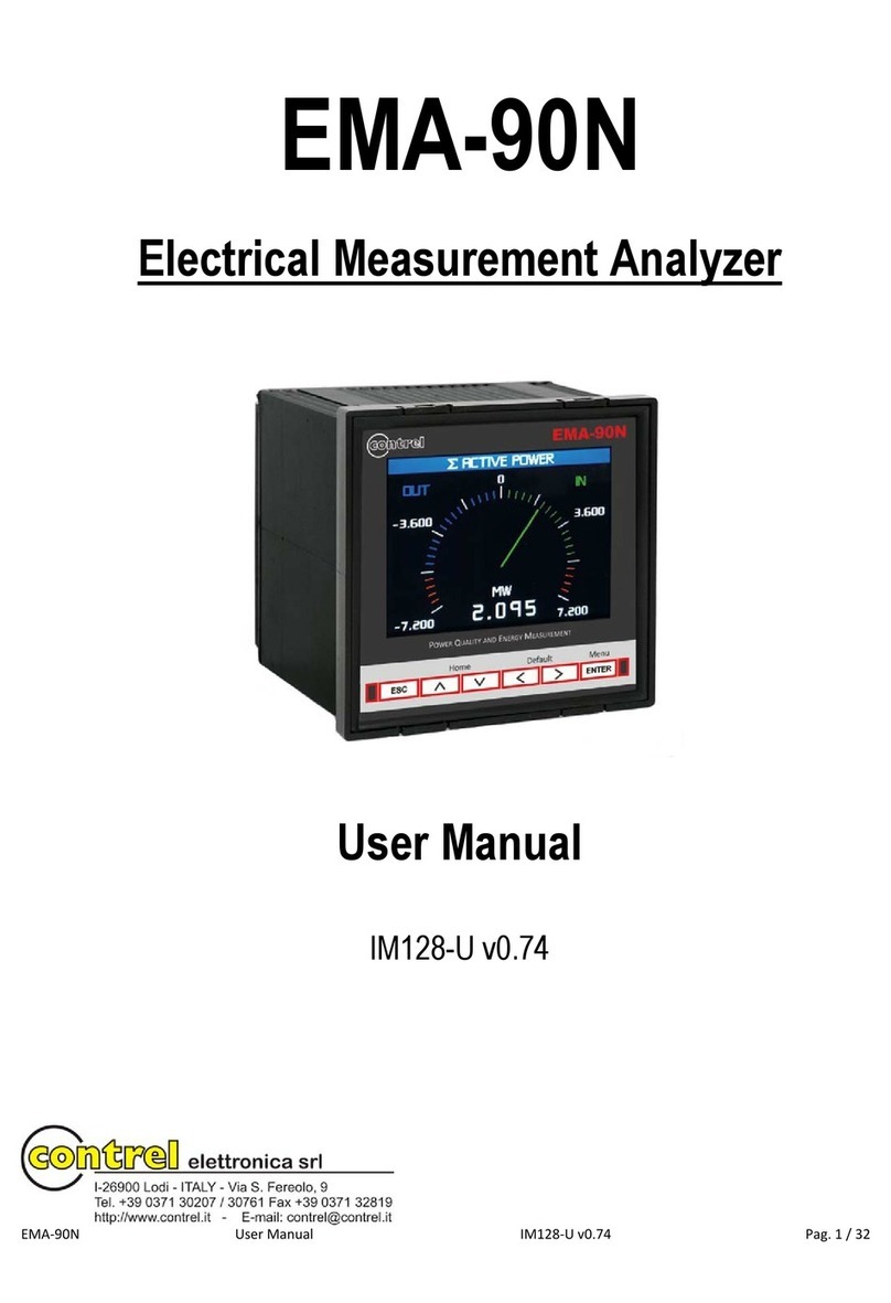
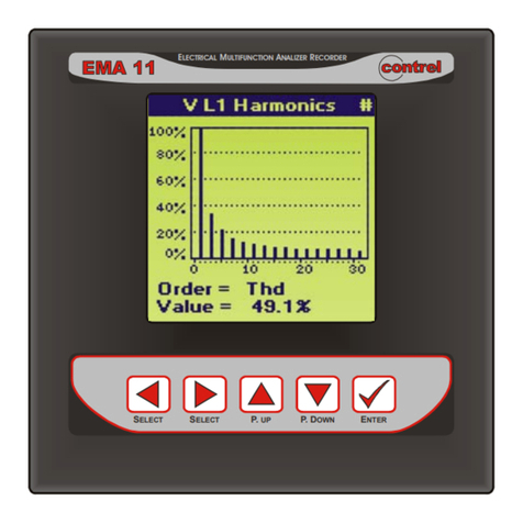
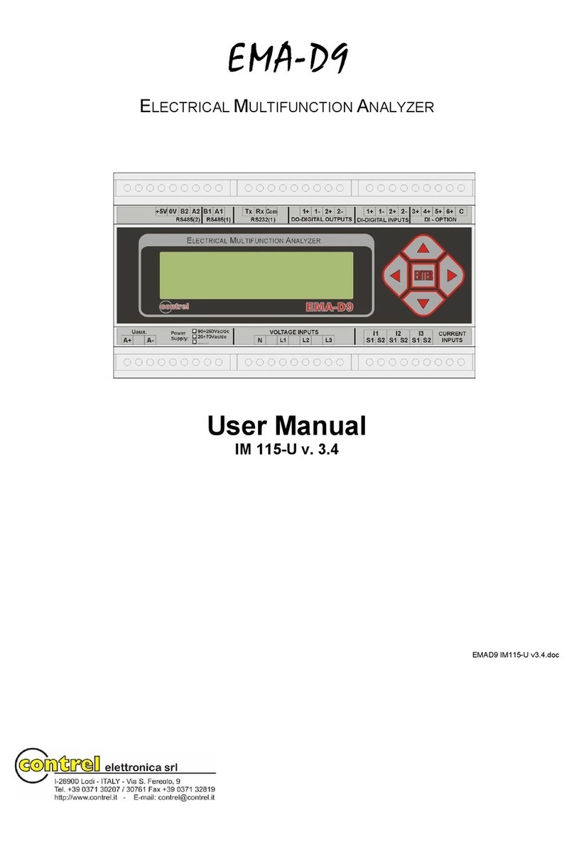
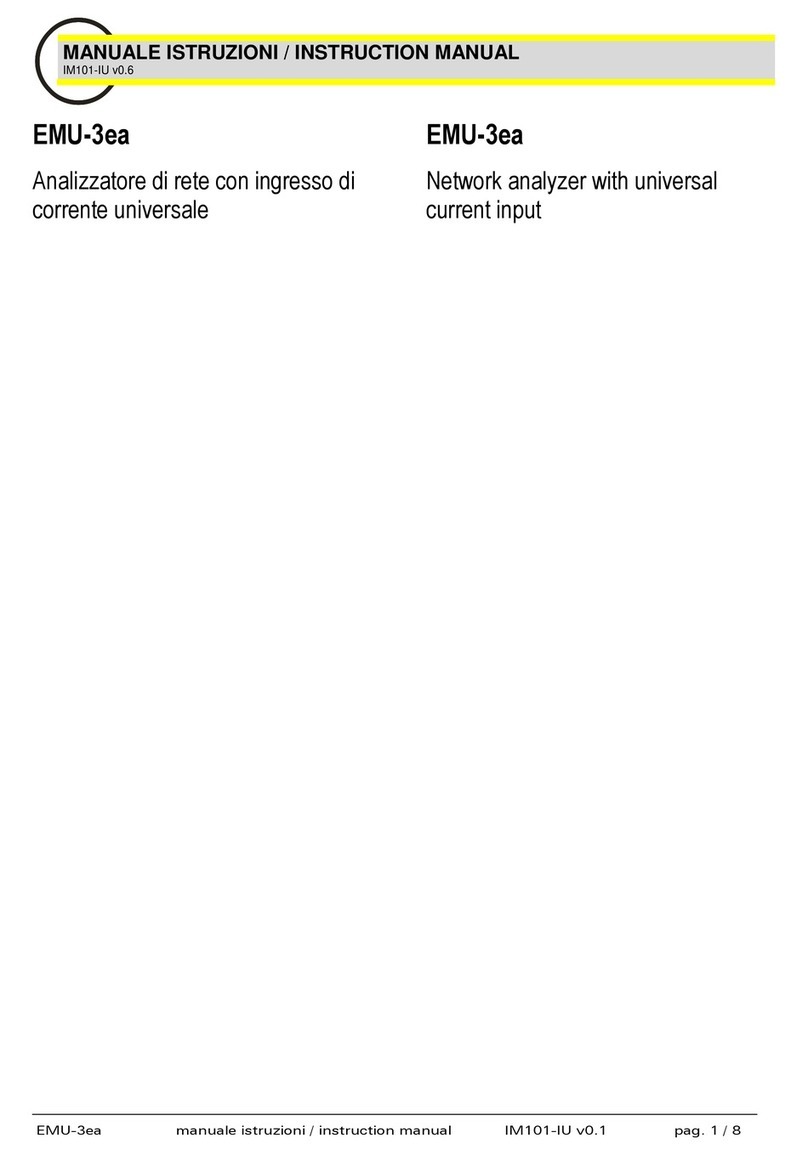
manuals.online logo
Brands
  1. Home
  2. •
  3. Brands
  4. •
  5. Contrel
  6. •
  7. Measuring Instrument
  8. •
  9. Contrel EMA-D6 User manual

Contrel EMA-D6 User manual

pag. 1 / 22
INSTRUCTION MANUAL
IM114-U v0.2
EMA-D6
DIN rail network analyzer
with basic power quality analysis
pag. 2 / 22
WARNING!
•Carefully read the manual before the installation or use.
•This device is to be installed by qualified personnel, complying to current standards, to avoid damages.
•Before any maintenance operation on the device, remove supply inputs.
•The manufacturer cannot be held responsible for electrical safety in case of improper use of the equipment.
•Products illustrated herein are subject to alteration and changes without
prior notice.
Introduction
The EMA-D6 is a Network Analyzer for displaying all the relevant system parameters in low and medium voltage power distribution. It is capable of single-phase,
two-phase or three-phase measurement and can be used in two-wire, three-wire, four-wire, TN, TT and IT systems.
Thanks to its large measured voltage range, the EMA-D6 with multi-range power supply can be connected in any low and medium voltage system up to a rated
system voltage of 690 VAC.
Higher voltages can be measured using voltage transformers. For measuring current, either x/1 A or x/5 A current transformer can be used or Rogowski coil
(optional), TT/TTA sensors (optional) or 333 mV (optional).
The combination of four function keys with the multi-language plaintext displays makes intuitive user prompting possible. The graphic color LCD offers user-friendly
interface.
The RS-485 or Ethernet interface or an optionally available interface module can be used for communication. In addition, the EMA-D6 has a multifunctional digital
output using an alarm. The analyzer can accept up to 4 digital inputs. The parameters can be set either direct on the device or via the communications interface.
Password protection is integrated via the front of the device to guard against unauthorized access.
Description
•Modular DIN-rail housing, 6 modules
•Backlighted LCD display
•True RMS measurements
•For current transformers x/1 A and x/5 A, Rogowski coil (optional), TT/TTA sensors (optional), 333 mV (optional)
•Keyboard with 4 keys for viewing and setting
•Easy and fast navigation
•Derivation of more than 50 measured variables from the basic measured variables with maximum, minimum, average and max demand values
•Continuous sampling (128 @ waveform)
•High measuring accuracy
•Harmonics V, I up to 63th order (optional)
•Up to 4 digital outputs
•Up to 4 digital inputs
•Up to 2 RS-485 communication (Modbus RTU protocol) (COM2 optional)
•ETHERNET interface (Modbus TCP protocol) (optional)
Voltage measurement
- Direct measurement on the system or using voltage transformers. External voltage transformers are required to measure higher voltages than the permissible
rated input voltages.
- Measuring voltage to 400 VAC / 690 VAC with multi-range power supply. The device is designed for measuring input voltages up to 400 VAC to the neutral
conductor and 690 VAC to Vph-ph.
Current measurement
- Measuring current of 1 A or 5 A for connecting standard current transformers. Rogowski coil (optional), TT/TTA sensors (optional).
Neutral or differential measurement
- The fourth current input channel (I4) is used to measure the current on the neutral line or differential current.
- If the CT for the neutral wire is not available, the measure of I4 input will be calculated from the phase currents.
LED and keyboard functions
A
Display
B
LED ON: presence of auxiliary supply
C
Communication traffic LED
D
Energy pulsing LED
E
LED used for notifications (alarms, warnings, errors)
F
Cancellation or navigation key among the visualization pages
G
Up
H
Down
I
Confirmation or navigation key among the visualization pages
pag. 3 / 22
Installation
1. Turn off all power supplying this device and the equipment in which it is installed before working on it.
2. Always use a properly rated voltage sensing device to confirm that all power is off.
Removing from a DIN rail
1. Using a flat screwdriver (≤ 6.5 mm / 0.25 in), lower the locking 2. Lift the device up to free it from the DIN rail.
clip to release the device.
First commissioning
At first power up of EMA-D6 network analyzers, wizard procedure will guide the user in the first commissioning steps:
1. Set the language (please refer to section “Utility menu”)
2. Set the type of wiring connection (please refer to section “Measure menu - Wiring connection”)
3. Set the current transformers primary and secondary (please refer to section “Measure menu - Transform ratio”)
4. Set the neutral current transformers primary and secondary (please refer to section “Measure menu- Transform ratio”)
5. Set the voltage transformers primary and secondary (please refer to section “Measure menu- Transform ratio”)
6. Set the date and time on the device (please refer to section “General menu - Date & Time”)
Access to device
The network analyzer features a front panel with signaling LEDs, a graphic color display and contextual menu buttons for accessing the information required to
operate and modify parameter settings. The navigation menu allows you to display, configure and reset parameters.
General display
The general display of the power metes is shown in the following picture:
A
Title bar
B
Favorite page
C
Phase indication
D
Measurements and unit of measure
E
Cancellation or navigation key among the visualization pages
F
Up
G
Down
H
Confirmation or navigation key among the visualization pages
I
To enter the menu and configuration mode
Info menu
Menu
Description
Device
Revision software-Revision hardware-Serial number-Info wiring-Work hours-Options info
I/O
Digital input/output status-Analog output status
Setpoint
Info setpoints
Date/Time
Time and date
COM monitor
Communication traffic (RS-485 and Ethernet)
Log summary
Info logs
Log details
Viewing logs
ON/OFF events
Power supply switch ON/OFF
pag. 4 / 22
Table of display pages
•INST = Instantaneous value –Actual instantaneous value of reading, shown by default every time the page is changed
•MAX = Highest peak –Highest peak of the instantaneous value of the relative reading. They can be cleared using dedicated command (see reset menu).
•MIN = Lowest peak –Lowest value of reading. They can be cleared using the same command used for MAX values.
•AVG = Average value –Time-integrated value of reading. Allows showing measurements with slow variations.
•MD = Maximum Demand –Maximum peak of the integrated value.
PARAMETER
Selection with ▲and ▼
INST
MAX
MIN
AVG
MD
1
PHASE-TO-PHASE VOLTAGES - V(L1-L2), V(L2-L3), V(L3-L1), V(SYS)
●
●
●
●
2
PHASE-TO-NEUTRAL VOLTAGES - V(L1-N), V(L2-N), V(L3-N), V(L-N)
●
●
●
●
3
PHASE AND NEUTRAL CURRENTS - I(L1), I(L2), I(L3), I(N)
●
●
●
●
●
4
POWER FACTOR - PF(L1), PF(L2), PF(L3), PF(SYS)
●
5
COS-PHI - COS-PHI(L1), COS-PHI L2), COS-PHI(L3), COS-PHI(SYS)
●
6
TANGENT-PHI -TAN-PHI(L1), TAN-PHI(L2), TAN-PHI(L3), TAN-PHI(SYS)
●
7
ACTIVE POWER - P(L1), P(L2), P(L3), P(SYS)
●
●
●
●
●
8
REACTIVE POWER - Q(L1), Q(L2), Q(L3), Q(SYS)
●
●
●
●
●
9
APPARENT POWER - S(L1), S(L2), S(L3), S(SYS)
●
●
●
●
●
10
VOLTAGE TOTAL HARMONIC DISTORTION - THD-V(L1), THD-V(L2), THD-V(L3)
●
11
CURRENT TOTAL HARMONIC DISTORTION - THD-I(L1), THD-I(L2), THD-I(L3)
●
12
VOLTAGE CREST FACTOR
●
13
CURRENT CREST FACTOR
●
14
FREQUENCY - F(L1), F(L2), F(L3), F(SYS)
●
●
●
●
15
ENERGY METERS
kWh+(TOT), kWh-(TOT), kVArh+(TOT), kVArh-(TOT), kVA(TOT)
kWh+(L1), kWh-(L1), kVArh+(L1), kVArh-(L1), kVA(L1)
kWh+(L2), kWh-(L2), kVArh+(L2), kVArh-(L2), kVA(L2)
kWh+(L3), kWh-(L3), kVArh+(L3), kVArh-(L3), kVA(L3)
●
16
PHASE ANGLE V-V
●
17
PHASE ANGLE V-I
●
18
* VOLTAGE HARMONICS DISTORTIONS - H2…63 V(L1)-V(L2)-V(L3)
●
19
* CURRENT HARMONICS DISTORTIONS - H2…63 I(L1)-I(L2)-I(L3)
●
* only version EMA-D6 H
Parameter setting (SETUP)
- At normal display of readings, to enter configuration mode, press ▲and ▼keys.
- Select the required sub-menu with ▲▼keys and confirm with
- To exit setup and go back to the readings viewing press
- The following table show the available sub-menus:
Menu
Description
General
Date and time, language, password, display utility, reset commands
Measure
CT and VT ratio, type of wiring, frequency, dip/swell configuration, measurements settings, energy preload
User pages
User-defined pages
Communication
Communication port parameters (COM1, COM2, Ethernet)
I/O
Digital outputs, digital inputs, analog outputs
Setpoint
Limit thresholds on readings
Log
Data recording settings
Logic expression
Programmable mathematical calculation functions (sum of meters, relations between quantities, etc.)
Modifying parameters
To modify the setting of one parameter, select it with ▲and ▼keys and then press
There are two methods for modifying a parameter, depending on the type of parameter:
•Selecting a value in a list (for example, selecting SINGLE-PHASE from a list of available wiring connections).
•Modifying a numerical value, digit by digit (for example, entering a value for the date, time or VT primary).
Selecting the value in a list
To select a value in a list:
1. Use the ▲or ▼keys to scroll through the parameter values until you reach the desired value.
2. Press to confirm the new parameter value. The entered value is stored.
Modifying the numerical value
When you modify a numerical value, the digit on the far right side is selected by default. To modify a numerical value:
1. Use the ▲or ▼keys to modify the selected digit.
2. Use the ◄or ►keys to shift to the next digit.
3. Press to confirm the new parameter value. The entered value is stored.
- Each parameter is show with present value and the possible range values.
NOTE: If you enter an invalid setting and press , the message “Value out of range”will appear on display.
pag. 5 / 22
Harmonic analysis page (optional)
- The EMA-D6 provides the harmonic analysis up to 63rd order of the following measurements:
•phase-to-phase voltages
•phase-to-neutral voltages
•currents
- For each of these measurements, there is a display page that graphically represents the harmonic content using a bar graph.
- Every column is related to one harmonic order, even and odd.
- Every display page is related to each phase L1, L2, L3.
- The value of the harmonic content is expressed as a percentage.
- It is possible to show the harmonic content in numeric format, pressing ►button.
- The vertical scale of the graph is automatically selected, depending on the column with the highest value.
Waveform page
- These pages graphically view the waveform of the measured voltages and currents.
- It’s possible to see one phase at the time, selecting it with ►button, or 3 phase system page.
- The vertical scale is automatically scaled in order to fit the waveforms on the screen.
- The graph is automatically updated every refresh time selected by the user (DISPLAY menu).
- Every page shows the total harmonic distortion (THD) and the instantaneous value for each these measurements.
Trend graph page
- The trend graph page allows to show the changes in the time of phase-to-neutral voltages and currents. This functionality provides a real-time snapshot of network
condition.
- It’s possible to see, on the graph, the history of last 60 values of the measurement, each correspondent to every 2 seconds of instantaneous value.
- When the maximum storing capacity is exceeded, the newest data will overwrites the oldest, so that the most recent data is always shown.
- The vertical full-scale is calculated automatically.
Power bar-graph page
- This page graphically view the daily power consumption (24 hours) of the active and reactive powers read by the EMA-D6.
- It’s possible to see one day at a time, selecting it by clicking ►button.
- The vertical full-scale is calculated automatically, depending on the column with the highest value.
pag. 6 / 22
Energy bar-graph page
- These pages graphically view the daily, weekly, monthly and yearly energy counters consumption of the active (IN and OUT) and reactive (IN and OUT)
energy read by the EMA-D6. For every graph, the unit displays the 4 total counters (Wh IN, Wh OUT, VArh IN, VArh OUT).
- It’s possible to see one day at a time, selecting it by clicking ►button.
- It’s possible to clear completely through the dedicated command in the RESET menu.
- If a count is not available, then some empty spaces are shown.
Phasors page
- The phasor diagram shows voltages and currents in relation to each other.
- The currents are depicted within the inner circle while the voltages are shown within the outer circle.
- It’s possible to see, on the this page, the angle value between the phasors.
User pages
- The user can create a maximum of 4 favorited display pages .
-Each of these pages can view maximum 6 measurements, freely chosen among all reading of the EMA-D6.
- The title of the page can be freely programmed by the user.
- Like all other pages, it’s possible to set the analyzer to return automatically to the user page after a time has elapsed.
- To define the user page, see the dedicated menu USER PAGE chapter.
Time and date
- The EMA-D6 manages the date and time, that is used for storage of events, for measurements log and for time-related functionalities.
- The EMA-D6 is equipped with RTC (real-time clock), then the time and date are kept updated even without auxiliary power supply, for a maximum of about 1 week.
- Setting date and time is mandatory in order to use the time-related functionalities on the device (maximum, minimum, historical).
Password access
- The password is used to enable or lock the access to:
•setting menu
•display viewing
•keys
•communication
- For new devices, the password management is disabled and the access is free. If instead the password have been enabled, then to get access or change any
configuration of the device, it’s mandatory to enter the password.
- The password is valid as soon as the user remains in the Configuration section or others lock sections and for a max setting minutes (see the dedicated menu
PASSWORD chapter).
- After quitting the Configuration section or others lock sections, it’s needed to enter again the password.
Additional resources
- The options provide additional resources that can be used through a dedicated setup menus.
- The following table indicates the optional additional resources:
TYPE
Function
Max Number
Communication
RS-485
2
Ethernet
1
Digital I/O
Outputs
4
Inputs
4
2 Inputs + 2 Outputs
2+2
Analog I/O
4 Analog Outputs (external module)
4
8 Analog Outputs (external module)
4
Memory
Data memory 4MB
1
pag. 7 / 22
Communication channels
- The EMA-D6 supports a maximum of 2 RS-485 communication channels (COM1 and COM2) and a maximum of 1 Ethernet port.
- The communication channels are completely independent and can communicates at the same time.
Daisy-chaining devices to the network analyzer
The RS-485 slave port allows the network analyzer to be connected in a daisy chain with up to 32, 2-wire devices. See Figure below.
Setpoint thresholds
- The setpoint thresholds are internal variables whose status depends on the out of limits of one particular measurement set by user among all those measured
(example: active power higher than 40 kW).
- For each setpoint, there are 2 thresholds (upper and lower). The upper threshold must always be set toa value higher than the lower threshold.
- For every setpoint is possible to set a delay when alarms is triggered on and off.
- When specific conditions are met, alarms is turned on or off. Triggering of alarms can be registered in the devices notifications log, in the events section, increasing
timer. In addition to that, they can be set up to control digital outputs of the device.
- There are two types of setpoints available on EMA-D6: simple setpoint and “complex”condition to a setpoint using Boolean logic variables (AND, OR).
- For setpoint thresholds programming and definition refer to setup menu SETPOINT chapter.
For more information on how the meter handles the setpoint-driven alarms, refer to the figure below.
Data logger function
- The data logger allows to store at regular interval up to 14 variables chosen freely among the multimer measures.
- Every record is marked with a timestamp taken from the internal real-time clock. The minimum sampling period (distance between two records) is of 1 second.
- Considering the amount of memory, the number of variables to be stored and sampling period, the unit indicates the time that must elapse before the memory is
completely filled.
- The recording can be continuous (driven only by regular time intervals) or conditional (between a specified date/time range), driven only by the status of the internal
variables (setpoint) or digital input status.
- When the memory is full, the user can choose to stop the recording (End Memory mode) or to continue overwriting the oldest records (FIFO mode).
- The display page dedicated to the data logger info (MENU - INFO - LOG SUMMARY) shows all the fundamental information: number of records, sampling,
available free memory, residual time before the memory if filled (when working in End Memory mode).
A
The measurement monitored by setpoint.
B
Trigger delay.
C
The alarm is turned on.
D
The alarm is turned off.
Upper threshold
Lower threshold
Hours
Recording status
Sampling period
Percentage of used
memory
Time left before end
of memory
expressed in days
hh:mm
pag. 8 / 22
Configuration setup menu tree
NOTE: * thanks to supported expansion module MR-AO
Setup
General
Measure
User pages
Communication
I/O
Setpoint
Log
Logic expression
Password
Reset
Date / Time
Utility
Display
Graphics
Editing contacts
Transform ratio
Time window
Frequency
DIP / SWELL
Wiring / Convention
Type / Modality
Energy / Counter
Ethernet LAN
COM 1
COM 2
Digital outputs
Digital inputs
Analog outputs *
Parameters
Text
Generic
Smart
Preload energies
Mode
Daily plan
Period plan
Holiday
pag. 9 / 22
Parameters table
Below are listed all the programming parameters. For each parameter are indicated the setting range, the factory default, as well as a description of the function.
GENERAL menu
PASSWORD
UoM
Default
Range
1
Level 1 (viewing)
-
0
0 (OFF)-999999999
2
Level 2 (setup)
-
0
0 (OFF)-999999999
3
Key enabling
min
5
1-60
4
Key lock
-
NO
YES-NO
5
Communication lock
-
NO
YES-NO
6
Enable options
-
0
0 (OFF)-999999999
NOTE: Password Recovery. If you forget your password, contact Technical Support.
1- When the password is defined, value to be specified to allow the user to scroll the pages.
2- When the password is defined, value to be specified to get user configuration access.
3- Setting the minutes for which the password enables the protected functions.
4- If set to YES, the password protects the use of the keys. Enter numeric code to unlock the keys.
5- If set to YES, the password protects the communication setup messages on the serial or TCP bus.
6- Numeric code that unlock firmware functions.
RESET
Range
1
Global
All device parameters are resetted to factory default value.
2
Setup to default
All setup parameters are resetted to factory default value.
3
All energies
Clears total and tariff energy meters.
4
TB energies
Clears tariff energy meters.
5
Counters
Clears counters.
6
TB counters
Clears tariff counters.
7
MIN-MAX
Reset of MAX and MIN peaks of all readings.
8
Max Demand
Reset of Max Demand of all readings.
9
Energy graphs
Clears the energy graphics.
10
Log setpoint
Clears the alarm log events.
11
All log
Clears the log memory (both events and measurements log).
12
ON / OFF events
Clears the power supply switch ON/OFF events.
13
Setpoint DO
Manual command in order to reset the digital output of the alarm setpoint.
14
DIP / SWELL
Clears the DIP / SWELL log memory.
DATE AND TIME
- The EMA-D6 manages the date and time, that is used for the storage events and for time-related functions. The EMA-D6 is equipped with a module with RTC
(real-time clock), then the time and date are kept updated even without auxiliary power supply, for a maximum of about 1 week.
UTILITY
Default
Range
1
Language
English
English
Italiano
Deutsche
Francais
Svenska
Espanol
2
Theme
Blue-Black
Blue-Black…White
Red-Black…White
Yellow-Black…White
Grey-Black…White
3
Font dimension
Standard
Standard-Big
4
Set-point alert
OFF
ON-OFF-First Out
5
Protocol
Standard
Standard-(old EMA devices)
4- When it is activated the display page switches automatically on the alarm page, and the alarm is shown with the Warning icon.
5- When it is selected the old devices, the communication protocol switches on the old EMA-90.
DISPLAY
UoM
Default
Range
1
Brightness
-
15
1-15
2
Default page return
-
NO
NO-YES
3
Stand-by
-
YES
NO-YES
4
Stand-by time
min
10
1-60
5
Refresh
ms
4
1-60
1- Set up the level of brightness display.
2- If set to NO the display will remains in the page where the user left it. If set to a time delay, after that time the display page goes back to page set as default.
4- Set up the time after that the display will switch off. The lifetime of the graphical display depends on its brightness and stand-by time. It is highly recommended to
limit the brightness level of the display in order to ensure a longer lifetime of the device.
5- Display update time. Note: 1 = 250 ms
pag. 10 / 22
MEASURE menu
TRANSFORM RATIO
UoM
Default
Range
1
CT primary
A
1
1-400000
2
CT secondary
A
1
1-400000
3
CT N primary
A
1
1-400000
4
CT N secondary
A
1
1-400000
5
VT primary
V
1
1-400000
6
VT secondary
V
1
1-400000
Note: If Rogowski coils are used, it is not needed to set any transformation ratio.
1- CT primary winding rated current.
2- CT secondary winding rated current.
3- CT Neutral primary winding rated current.
4- CT Neutral secondary winding rated current.
5- VT primary winding rated current.
6- VT secondary winding rated current.
INTEGRATION
UoM
Default
Range
1
Time interval
min
15
1-2-3-5-6-10-12-15-20-30-60
2
Type
-
Shifting
Shifting-Fixed
1- Selection the integration time interval.
2- Selection of average reading calculation mode:
Shifting = The instantaneous values are integrated for a period.
Fixed = Readings are integrated for a fixed rated. Every time the integration time elapses, the average value is updated with the result of the last integration.
FREQUENCY
UoM
Default
Range
1
Fundamental
Hz
50
50-60
1- Rated frequency of the line. Possible nominal frequency values: 50 Hz or 60 Hz.
DIP / SWELL
UoM
Default
Range
1
DIP threshold
mV
190000
10-10000000
2
DIP cycles
cycles
250
1-10000
3
SWELL threshold
mV
270000
10-10000000
4
SWELL cycles
cycles
250
1-10000
5
Interruption threshold
mV
205000
10000-2000000000
6
Interruption hysteresis
mV
275000
10000-2000000000
7
Storage
-
End memory
FIFO
End memory
1- Threshold active when the voltage is lower than value set.
2- The duration of voltage dip. Note: 1 = 20 ms
3- Threshold active when the voltage is higher than value set.
4- The duration of swell over-voltages. Note: 1 = 20 ms
5- Voltage interruption begins when the RMS value falls below this threshold. A voltage interruption ends when the voltage is equal to, or greater than, interruption
threshold plus the hysteresis.
6- Hysteresis delay on voltage interruption.
7- When the memory is full, the user can choose to stop the recording (end memory) or to continue overwriting the oldest records (FIFO).
WIRING / CONVENTION
UoM
Default
Range
1
Wiring
-
3 phase (4 or 3 wires)
ARON
3 phase balanced
3 phase multiload balanced
Single phase
Single phase multiload
Triple single phase
Two-phase (3 wires)
2
4th input current
-
Measured
Computed-Measured
Differential-Differential filter
3
PF convention
-
SIGN
SIGN-IEC-IEEE
4
Setpoint timing
s
1
0.1 or 1
1- Set this parameter according to the used wiring diagram. See wiring diagrams section on the manual.
2- The fourth current input channel (I4) is used to measure the current on the neutral line or differential current. If the CT for the neutral wire is not available, the I4
input can be calculated from the phase currents.
3- The meter shows positive or negative power factor according to selected standard.
4- Set the setpoint intervention time.
pag. 11 / 22
TYPE / MODALITY
UoM
Default
Range
1
Unit of measure
-
mV-mA-W-kWh
mV-mA-mW-Wh
mV-mA-W-kWh
V-A-kW-MWh
2
Modality
-
Bidirectional
Bidirectional-Monodirectional
3
Compute Idiff (I1+I2+I3+IN)
-
NO
YES-NO
4
THD avg
samples
1
1-10
1- Set this parameter according to the measurements .
2- If set bidirectional, the energy meters shows imported/exported active energy, inductive/capacitive reactive energy.
3- If set YES, the calculation for differential current will be considering I1+I2+I3+IN.
4- Set the sample for THD average calculation.
ENERGY menu
PRELOADED
UoM
Default
Range
1
Wh+ L1
0.1 k
0
0-1000000000
2
Wh- L1
0.1 k
0
0-1000000000
3
VArh+ L1
0.1 k
0
0-1000000000
4
VArh- L1
0.1 k
0
0-1000000000
5
Vah L1
0.1 k
0
0-1000000000
6
Wh+ L2
0.1 k
0
0-1000000000
7
Wh- L2
0.1 k
0
0-1000000000
8
VArh+ L2
0.1 k
0
0-1000000000
9
VArh- L2
0.1 k
0
0-1000000000
10
Vah L2
0.1 k
0
0-1000000000
11
Wh+ L3
0.1 k
0
0-1000000000
12
Wh- L3
0.1 k
0
0-1000000000
13
VArh+ L3
0.1 k
0
0-1000000000
14
VArh- L3
0.1 k
0
0-1000000000
15
Vah L3
0.1 k
0
0-1000000000
1..5 - Set a value of energy meters (L1) for: active energy imported and exported, reactive energy inductive and capacitive, apparent energy.
6..10 - Set a value of energy meters (L2) for: active energy imported and exported, reactive energy inductive and capacitive, apparent energy.
11..15 - Set a value of energy meters (L3) for: active energy imported and exported, reactive energy inductive and capacitive, apparent energy.
TIMEBAND
UoM
Default
Range
1
Energy change
-
Manual
From command-From DI-Preset-From key
2
Energy TB
-
1
1..16
3
Counter change
-
Manual
From command-From DI-Preset-From key
4
Counter TB
-
1
1..16
1 - Set the energy meters tariff selection: command (dedicated command via Modbus protocol), by the change in digital inputs (their binary combination selects the
tariff as shown in table), preset (by daily, period plan), keys (by frontal keyboard).
2 - When energy timeband selection is made by keys, select among the 16 timebands.
3 - Set the counters selection: manual (dedicated command via Modbus protocol), by the change in digital inputs (their binary combination selects the tariff as shown
in table), preset (by daily, period plan), keys (by frontal keyboard).
4 - When counter timeband selection is made by keys, select among the 16 timebands.
DIG. INPUT-4
DIG. INPUT-3
DIG. INPUT-2
DIG. INPUT-1
TIMEBAND
0
0
0
0
1
0
0
0
1
2
0
0
1
0
3
0
0
1
1
4
0
1
0
0
5
0
1
0
1
6
0
1
1
0
7
0
1
1
1
8
1
0
0
0
9
1
0
0
1
10
1
0
1
0
11
1
0
1
1
12
1
1
0
0
13
1
1
0
1
14
1
1
1
0
15
1
1
1
1
16
pag. 12 / 22
DAILY PLAN n (n=1..16)
UoM
Default
Range
1
Start hour
hour
0
0-23
2
Start minute
min
0
0-59
3
Timeband used
-
TB n
TB1..16
NOTE: this menu is divided into 16 sections, for DAILY PLAN1..16. Each DAILY PLAN supports a maximum of 16 time segments.
1 - Configuring the start hour.
2 - Configuring the start minute.
3 - Select among the 16 timebands.
PERIOD PLAN n (n=1..16)
UoM
Default
Range
1
Enable
-
NO
YES-NO
2
Start month
-
January
January..December
3
Start day
-
1
1..31
4
End month
-
December
January..December
5
End day
-
31
1..31
6
Monday
-
Daily plan 1
Daily plan 1..16
7
Tuesday
-
Daily plan 1
Daily plan 1..16
8
Wedsnday
-
Daily plan 1
Daily plan 1..16
9
Thursday
-
Daily plan 1
Daily plan 1..16
10
Friday
-
Daily plan 1
Daily plan 1..16
11
Saturday
-
Daily plan 2
Daily plan 1..16
12
Sunday
-
Daily plan 3
Daily plan 1..16
NOTE: this menu is divided into 16 sections, for PERIOD PLAN1..16.
1 - Enables period plan.
2 - Configuring the start month.
3 - Configuring the start day.
4 - Configuring the end day.
5 - Configuring the end month.
6..12 - Weekdays selection of schedule mode among the 16 daily plans.
HOLIDAY n (n=1..48)
UoM
Default
Range
1
Month holiday
-
January
January..December
2
Day holiday
-
1
1..31
3
Plan holiday
-
Daily plan 1
Daily plan 1..16
NOTE: HOLIDAY menu supports a maximum of 48 holidays.
1 - Configuring the month.
2 - Configuring the day.
3 - Selection of schedule mode among the 16 daily plans.
USER PAGES menu
PAGE TYPE
UoM
Default
Range
1
User page type
-
Instantaneous
Instantaneous
Average
Energy
Setpoint
NOTE: this menu is divided into 4 sections, for user pages PAG1..4
1- Set measurements category that will be shown in the frames of the user pages.
COMPOSITION PAGE
UoM
Default
Range
1
Row 1
-
OFF
OFF - (measurements)
2
Row 2
-
OFF
OFF - (measurements)
3
Row 3
-
OFF
OFF - (measurements)
4
Row 4
-
OFF
OFF - (measurements)
5
Row 5
-
OFF
OFF - (measurements)
6
Row 6
-
OFF
OFF - (measurements)
NOTE: this menu is divided into 4 sections, for user pages PAG1..4
1, 2, 3, 4, 5, 6 - Measurement that will be shown in the six rows of the user pages (according to the user page type selection).
TITLE PAGE
UoM
Default
Range
1
Title 1
-
TITLEn
(Text - 20 char)
2
Title 2
-
TITLEn
OFF - (measurements)
3
Title 3
-
TITLEn
OFF - (measurements)
4
Title 4
-
TITLEn
OFF - (measurements)
NOTE: this menu is divided into 4 sections, for user pages PAG1..4
1, 2, 3, 4 - Title of the user page. Free text, 20 chars.
pag. 13 / 22
COMMUNICATION menu
COMn (n=1..2) (COM2 optional)
UoM
Default
Range
1
Mode
-
Slave
Slave - Master - Gateway
2
Devices read
-
1
1-20
3
Master timeout
ms
0-10000
800
4
Scan rate
ms
0-10000
1000
5
Serial node
-
1
1-247
6
Serial speed
-
38400
4800…115200
7
Stop bits
-
1
1-2
8
Data format
-
8 bit, no parity
8 bit, no parity
8bit, odd
8 bit, even
9
MIN response delay
ms
5-100
10
NOTE: this menu is divided into 2 sections, for comm channels COM1..2 (COM2 optional)
1 - Set the communication function. Slave = Awaits connection from a remote master. Master = Establishes a connection to the remote devices. Gateway =
Activating this function it’s possible to use an EMA-D6 with both an Ethernet port and RS-485 port, that works as Modbus TCP bridge over other devices equipped
with RS-485 only, in order to achieve a more economic configuration (only one Ethernet port).
2 - When EMA-D6 will be configured as Master, set the number of devices connected to RS-485 port.
3 - When EMA-D6 will be configured as Master, set the timeout period on RS-485 port to collect the data.
4 - When EMA-D6 will be configured as Master, set the transmission polling time to collect the data.
5 - Serial address (node number) for the communication protocol. EMA-D6 will be configured as Slave.
6 - Serial communication speed.
7 - Number of stop bits.
8 - Data format.
9- Set the response delay period on RS-485 port when EMA-D6 will be configured as Slave.
ETHERNET (optional)
UoM
Default
Range
1
IP Address
-
10.0.0.100
000.000.000.000-255.255.255.255
2
Subnet mask
-
255.0.0.0
000.000.000.000-255.255.255.255
3
IP gateway
-
10.0.0.1
000.000.000.000-255.255.255.255
4
TCP port (1)
-
502
0-65535
5
TCP port (2)
-
503
0-65535
6
DHCP
-
OFF
OFF-ON
7
TCP timeout
s
4200
10-100000
NOTE: this menu is available only with Ethernet port. TCP-IP coordinates with Ethernet interface.
DIGITAL OUTPUT menu
DIGITAL OUTPUT (OUTn, n=1..4)
UoM
Default
Range
1
Status
-
0
0-1
2
Level
-
Normally open
Normally open - Normally closed
3
Mode
-
Status
Status - Pulse - Setpoint
Status memory - Pulse after write
4
Pulse weight (1 = 0.1k)
-
1
1-10000
5
Pulse period
ms
500
60-10000
6
Source associated
-
WhIN
Wh+,Wh-,VArh+,VARrh-,VAh
Wh+ L1,Wh- L1,VArh+ L1,VARrh- L1,VAh L1
Wh+ L2,Wh- L2,VArh+ L2,VARrh- L2,VAh L2
Wh+ L3,Wh- L3,VArh+ L3,VARrh- L3,VAh L3
NOTE: this menu is divided into 4 sections, for digital outputs OUT1..4 (OUT1,2 standard - OUT3,4 optional)
1- If set to 1, test to activate the output.
2- Normal status of the output. Allows reversing the logic of the output function.
3- Function of the output:
STATUS - Output linked to the status of the programmed variable.
PULSE - Energy count pulses.
SETPOINT - Allows connecting the status of an output to the status of a limit threshold of setpoint.
STATUS MEMORY - Defines if the status of an output remains at power on.
PULSE AFTER WRITE - Allows connecting the status of an output to the write command Modbus.
4- Quantity of energy.
5- Pulse duration.
6- Type of energy to which the pulse is linked to.
pag. 14 / 22
DIGITAL INPUT menu (optional)
DIGITAL INPUT (INPn, n=1..4)
Default
Range
1
Mode
Status
Status - Counter - Change energy TB - Change
Counter TB - Change energy and counter TB -
External trigger - Reset SP-DO
2
Multiplier
1
1-100000
3
Divisor
1
1-100000
4
Level action
Normally open
Normally open - Normally closed
5
SP-DO reset
-
Setpoint 1...Setpoint 32
6
Unit of measure
-
(Text - 20 char)
7
Description
-
(Text - 20 char)
NOTE: this menu is divided into 4 sections, for digital inputs INP1..4
1- Function of the input:
Status - Signal that generates the activation of the input.
Counter - Signal that causes the increment of the counter.
Change energy TB - Energy Timeband selection. See Energy timeband chapter.
Change Counter TB - Counter Timeband selection. See Energy timeband chapter.
Change energy and counter TB - Energy and Counter Timeband selection. See Energy timeband chapter.
External trigger - When this input is activated (triggered), the correspondent command is executed.
Reset SP-DO - When this input is activated (triggered), the correspondent setpoint reset is executed.
2- Multiplying factor. If digital input is using as input pulses counter, the pulse counter is multiplied by this coefficient.
3- Dividing factor. If digital input is using as input pulses counter, the pulse counter is divided by this coefficient.
4- Status on activation of the input. Allows reversing the logic of the input function.
5- When digital input is using as SP-DO reset, select the number of setpoint to reset.
6- Description of digital input. Free text 20 characters. If digital input is using as input pulses counter.
7- Unit of measure of digital input. Free text 20 characters. If digital input is using as input pulses counter.
EXPANSION MODULE ANALOG OUTPUT menu
Expansion Analog Output (AOn, n=1..8)
Default
Range
1
Output type
4…20mA
4…20mA
0…20mA
0…10V
0…5V
-10…10V
-5…5V
2
Source
Internal
Internal
3
Group
Instantaneous
Instantaneous
4
Item
-
OFF - (measures)
5
MAX value
0
-999999 - +999999
6
MAX unit
-
Unit measure of selected measurement
7
MIN value
0
-999999 - +999999
8
MIN unit
-
Unit measure of selected measurement
Note: this menu is divided into 8 sections, for external analog outputs board MR-AO…8
1- Defines the type of the analog sensor connected to analog output.
2- Electrical parameter that controls the value of analog output. INTERNAL - Measures provide from device.
3 - Measurements group. INSTANTANEOUS: Actual instantaneous values of reading.
4 - Select the electrical parameter from the selected group.
5- Define the value of the electrical parameter that corresponds to an output to the maximum of the range (20mA, 10V, +5V, etc…)
7- Define the value of the electrical parameter that corresponds to an output to the minimum of the range (0mA, 0V, -5V, etc…)
pag. 15 / 22
SETPOINT menu
SETPOINT (SPn, n=1..32)
UoM
Default
Range
1
Enable
-
OFF
OFF-ON
2
Source
-
Internal measures
Internal measures-(measures node 1-20)
3
Group
-
Instantaneous
Instantaneous-Average-Energies-Digital input-
Counter-Analog input-Math-Energy TB1..16-
Harmonics VL1..VL3- Harmonics IL1..IL3-
Diagnostic
4
Item
-
-
OFF-(measures)
5
High threshold
-
0
-99999999 - +99999999
6
High threshold unit
-
-
(Unit of measures)
7
Low threshold
-
0
-99999999 - +99999999
8
Low threshold unit
-
-
(Unit of measures)
9
Activation delay
s
1
0-100000
10
Deactivation delay
s
1
0-100000
11
Hysteresis
%
0
0-100
12
Logic operation over
-
OFF
OFF-OR-AND
13
Logic operation entry
-
OFF
OFF-OR-AND
14
Operands 1-16
-
15
Operands 16-32
-
16
Action over
-
OFF
Save event-DO change-Increase event-
Increase timer-Work hours
17
Action entry
-
OFF
Save event-DO change
18
DO used
-
OFF
DO1..4-EXT DO
NOTE: this menu is divided into 32 sections, for alarm setpoints SP1..32
1- If set to ON, the setpoint alarm is enabled.
2- Measurement source that generates the alarm. Internal measures or measures referred to the external devices (when EMA-D6 will be configured as
Master RS-485).
3- Measurement group that generates the alarm.
4 - Define which measurement of the device must be compared with limits.
5- Used to define the upper threshold.
6- Used to define the unit of measure of the upper threshold.
7- Used to define the lower threshold.
8- Used to define the unit of measure of the lower threshold.
9- Alarm delay on upper threshold.
10 - Alarm delay on lower threshold.
11 - Hysteresis for the previous thresholds.
12 - Logic operation between operands for the upper threshold.
13 - Logic operation between operands for the lower threshold.
14, 15 - Define which setpoint used as operands for the previous thresholds.
16 - Alarm notification:
SAVE EVENT - Log of alarm inside events list.
DO CHANGE - When the alarm is tripped, the correspondent digital output is triggered.
INCREASE EVENT - Increase the number of events above the alarm upper threshold.
INCREASE TIMER - When the alarm is tripped, the correspondent timer (hh:mm:ss) is activated.
WORK HOURS - Count of hours above the alarm upper threshold.
17 - Turn off alarm notification:
SAVE EVENT - Log of turn off alarm inside events list.
DO CHANGE - When the alarm is turning off, the correspondent digital output is triggered.
18 - If set DO change for the previous menu, define which digital output must be associated with an alarm.
SETPOINT (SPn, n=1..32)
UoM
Default
Range
1
Setpoint description
-
SETPOINT n
(text - 20 char)
NOTE: this menu is divided into 32 sections, for alarm setpoints SP1..32
1 - Alphanumeric description of the setpoint. Free text 20 characters.
pag. 16 / 22
LOG menu
GENERIC
UoM
Default
Range
1
Enable
-
OFF
OFF-Always-Between date-Between hour-
Between date and hour-Trigger
2
Sampling
-
15 min
1-2-3-5-6-10-12-15-20-30 sec
1-2-3-5-6-10-12-15-20-30-60 min
End of day
End of month
3
Storage
-
End memory
End memory / FIFO
4
Start month
-
January
January..December
5
Start day
-
1
1..31
6
Start hour
-
0
0..23
7
Start minute
-
0
0..59
8
End month
-
January
January..December
9
End day
-
1
1..31
10
End hour
-
0
0..23
11
End minute
-
0
0..59
12
Monday…Sunday
-
YES
YES-NO
13
Trigger input
-
DI active HIGH
DI active HIGH
DI active LOW
Setpoint
14
DI trigger
-
1
1..4
15
Setpoint trigger
-
1
1..32
16
Source 1..14
-
Internal measures
Internal measures-(measures node 1-20)
17
Group 1..14
-
-
Instantaneous-Average-Energies-Digital input-
Counter-Analog input-Math-Energy TB1..16-
Harmonics VL1..VL3- Harmonics IL1..IL3-
Diagnostic
18
Item 1..14
-
-
OFF-(measures)
1- Enable or disable the data logger function. Every record is marked with a timestamp taken from the real-time clock.
ALWAYS - The data logger allows to store at regular intervals up to 14 variables. The recording is continuous (driven only by regular time intervals).
BETWEEN DATE - The recording allows to store at regular intervals only between a specified date range.
BETWEEN HOUR - The recording allows to store at regular intervals only in the specified time interval.
BETWEEN DATE AND HOUR - The recording allows to store at regular intervals between a specified date range and time interval.
TRIGGER - The recording allows to store at regular intervals driven only by the status of the internal variables (setpoint) or digital input status.
2- Time interval between a data reading and the next one.
3- When the memory is full, you can choose to stop the recording (End Memory mode) or to continue overwriting the oldest records (FIFO mode).
4, 5, 6, 7 - Set the variables (driven by date range or/and time interval) that control the starting of the recording.
8, 9, 10, 11 - Set the variables (driven by date range or/and time interval) that control the ending of the recording.
12 - The recording can be disabled for a specific day of the week.
13 - Set the internal variables (setpoint) or digital input status to allows the recording.
14 - Define the number of digital input which controls the starting/ending of the recording.
15 - Define which setpoint controls the starting/ending of the recording.
16 - The data logger allows to store at regular interval up to 14 variables. To configure the data logger, it’s necessary to select the source variables (network
analyzer’s measures or from external devices).
17 - The data logger allows to store at regular interval up to 14 variables. To configure the data logger, it’s necessary to select the group variables.
18 - The data logger allows to store at regular interval up to 14 variables chosen freely among the network analyzer’s measures or from external devices.
SMART
UoM
Default
Range
1
Enable
-
OFF
OFF-Always-Between date-Between hour-
Between date and hour-Trigger
2
Sampling
-
15 min
1-2-3-5-6-10-12-15-20-30-60 min
End of day
End of month
3
Storage
-
End memory
End memory / FIFO
4
Group 1..14
-
-
Instantaneous
5
Item 1..14
-
-
OFF-(measures)
NOTE: the Smart data logger allows to store at regular interval:
1. The instantaneous value that the variable had at the moment of sampling.
2. The average value that the variable had in the sampling period.
3. The maximum value that the variable reached in the sampling period.
4. The minimum value that the variable reached in the sampling period.
Every record is marked with a timestamp taken from the real-time clock.
pag. 17 / 22
LOGIC EXPRESSION menu
LOGIC EXPRESSION n (n=1..8)
UoM
Default
Range
1
Enable
-
NO
YES-NO
2
Compute timing
sec/min
1 sec
1-2-3-5-6-10-12-15-20-30 sec
1-2-6-5-6-10-12-15-20-30-60 min
End of day
End of week
End of month
3
Source 1
-
-
Internal measures-(measures node 1-20)
4
Group 1
-
-
Instantaneous-Average-Energies-
Digital inputs-Counters-Analog input-Math
5
Item 1
-
-
OFF-(measures)
6
Multiplier 1
-
1
1-100000
7
Divisor 1
-
1
1-100000
8
Operation
-
Sum
Sum-Subtraction-Multiplication-Division
9
Source 2
-
-
Internal measures-(measures node 1-20)
10
Group 2
-
-
Instantaneous-Average-Energies-
Digital inputs-Counters-Analog input-Math
11
Item 2
-
-
OFF-(measures)
12
Multiplier 2
-
1
1-100000
13
Divisor 2
-
1
1-100000
NOTE: this menu is divided into 8 sections, for logic expression LE1..8
1- Expression enabled.
2- Selection of refresh calculation. Expression value is updated with the results of the last calculation.
3- First measurement source. Internal measures or measures referred to the external devices (when EMA-D6 will be configured as Master RS-485).
4- First measurement group that generates the alarm.
5 - Define which measurement of the device as the first operand.
6- Multiplying factor referred to previous measurement.
7- Dividing factor referred to previous measurement.
8- Math operation between first and second operands.
9, 10, 11, 12, 13 - (see above).
Power factor rules
pag. 18 / 22
Terminals connection
OPTIONAL DIGITAL OUT/IN CONFIGURATION:
Wiring connection
(1) Three-phase measuring, four conductors, unbalanced load, (2) Three-phase measuring, three conductors, unbalanced load, without
without voltage transformers, with current transformers. voltage transformers, with two current transformers. (ARON)
Connection type 3PH-4W Connection type ARON
N°
Description
N°
Description
N°
Description
1
Phase current IL1, input (S1)
10
Phase-to-neutral voltage VL1
19
Auxiliary supply (neutral or phase)
2
Phase current IL1, output (S2)
11
Not used
20
Not used
3
Phase current IL2, input (S1)
12
Phase-to-neutral voltage VL2
21
Auxiliary supply (neutral or phase)
4
Phase current IL2, output (S2)
13
Not used
22
Not used
5
Phase current IL3, input (S1)
14
Phase-to-neutral voltage VL3
23
A signal COM2 RS-485 (optional) *
6
Phase current IL3, output (S2)
15
Not used
24
B signal COM2 RS-485 (optional) *
7
Neutral current IN, input (S1) (optional) *
16
Neutral conductor VN
25
A signal COM1 RS-485
8
Neutral current IN, output (S2) (optional) *
17
Not used
26
B signal COM1 RS-485
9
Not used
18
Not used
27
Common = Ground RS-485
2 or 4 DIGITAL OUTPUTS
2 DIG. OUTPUTS - 2 DIG. INPUTS
4 DIGITAL INPUTS
N°
Description
N°
Description
N°
Description
28
Digital output 1 +
28
Digital output 1 +
28
Digital input 1 +
29
Digital output 1 -
29
Digital output 1 -
29
Digital input 1 -
30
Digital output 2 +
30
Digital output 2 +
30
Digital input 2 +
31
Digital output 2 -
31
Digital output 2 -
31
Digital input 2 -
32
Digital output 3 +
32
Digital input 1 +
32
Digital input 3 +
33
Digital output 3 -
33
Digital input 1 -
33
Digital input 3 -
34
Digital output 4 +
34
Digital input 2 +
34
Digital input 4 +
35
Digital output 4 -
35
Digital input 2 -
35
Digital input 4 -
36
Not used
36
Not used
36
Not used
pag. 19 / 22
(3) Three-phase measuring, three conductors, unbalanced load, with (4) Three-phase measuring, three conductors, balanced load, without
voltage transformers, with two current transformers. (ARON) voltage transformers, with one current transformer.
Connection type ARON Connection type 3PH BAL
(5) Single-phase measuring, two conductors, without voltage transformers, (6) Three-phase measuring, four conductors, balanced multiple loads,
with one current transformer. with three current transformers.
Connection type 1PH Connection type 3PH ML BAL
(7) Single-phase measuring, two conductors, without voltage transformers, (8) Two-phase measuring, three conductors, unbalanced loads, without
with one current transformer. voltage transformers with two current transformers.
Connection type 1PH ML Connection type 2PH 3W
pag. 20 / 22
(9) Single-phase measuring, two conductors, with voltage transformers,
with three current transformer.
Connection type 3X1PH
Digital outputs connection
L
Load
F
Fuse
V
12÷250 VAC / 150 mA max
10÷300 VDC / 150 mA max
Digital inputs connection
Input voltage
24 or 48 or 115 or 230 VAC/DC
(to be defined during the order)
Input current
5 mA max
Input config
2 terminals (A-K) for each input: NPN, PNP

Other Contrel Measuring Instrument manuals

Contrel RMS-12 User manual

Contrel

Contrel RMS-12 User manual

Contrel EMM-m3-VA User manual

Contrel

Contrel EMM-m3-VA User manual

Contrel EMM-4h User manual

Contrel

Contrel EMM-4h User manual

Contrel EMC Series User manual

Contrel

Contrel EMC Series User manual

Contrel EMA90 User manual

Contrel

Contrel EMA90 User manual

Contrel EMA-D9 User manual

Contrel

Contrel EMA-D9 User manual

Contrel RI-R44-V User manual

Contrel

Contrel RI-R44-V User manual

Contrel EMA-90N User manual

Contrel

Contrel EMA-90N User manual

Contrel ELRC-1 User manual

Contrel

Contrel ELRC-1 User manual

Contrel RI-SM User manual

Contrel

Contrel RI-SM User manual

Contrel EMS-96 User manual

Contrel

Contrel EMS-96 User manual

Contrel EMM-D4h User manual

Contrel

Contrel EMM-D4h User manual

Contrel EMA11 User manual

Contrel

Contrel EMA11 User manual

Contrel CTT8 User manual

Contrel

Contrel CTT8 User manual

Contrel EMU-3ea User manual

Contrel

Contrel EMU-3ea User manual

Contrel CTT8 User manual

Contrel

Contrel CTT8 User manual

Popular Measuring Instrument manuals by other brands

SED 024.86.119 operating instructions

SED

SED 024.86.119 operating instructions

Agilent Technologies NFA Series Setup guide

Agilent Technologies

Agilent Technologies NFA Series Setup guide

VOLTCRAFT MF-10 operating instructions

VOLTCRAFT

VOLTCRAFT MF-10 operating instructions

SEW 2950 CL instruction manual

SEW

SEW 2950 CL instruction manual

Dostmann TA 888 manual

Dostmann

Dostmann TA 888 manual

CAO Group Precise LTM Operator's manual

CAO Group

CAO Group Precise LTM Operator's manual

Calculated Industries PREXISO X2 quick start guide

Calculated Industries

Calculated Industries PREXISO X2 quick start guide

PCE Health and Fitness PCE-WL 1 user manual

PCE Health and Fitness

PCE Health and Fitness PCE-WL 1 user manual

Rohde & Schwarz Hameg HZ040 manual

Rohde & Schwarz

Rohde & Schwarz Hameg HZ040 manual

Universal Laser Systems ULTRA X6000 user guide

Universal Laser Systems

Universal Laser Systems ULTRA X6000 user guide

KLS Martin group LIMAX 120 operating instructions

KLS Martin group

KLS Martin group LIMAX 120 operating instructions

Niigata seiki FTM-52FN user manual

Niigata seiki

Niigata seiki FTM-52FN user manual

SureCall SC-METER-01 user manual

SureCall

SureCall SC-METER-01 user manual

Compass GOPLANET Mars 100 User's operation manual

Compass

Compass GOPLANET Mars 100 User's operation manual

Consilium OPSIS M800 Commissioning manual

Consilium

Consilium OPSIS M800 Commissioning manual

Hanna Instruments HI 721 quick start guide

Hanna Instruments

Hanna Instruments HI 721 quick start guide

DeFelsko PosiTector IRT instruction manual

DeFelsko

DeFelsko PosiTector IRT instruction manual

sauermann Si-HH3 user manual

sauermann

sauermann Si-HH3 user manual

manuals.online logo
manuals.online logoBrands
  • About & Mission
  • Contact us
  • Privacy Policy
  • Terms and Conditions

Copyright 2025 Manuals.Online. All Rights Reserved.