Controlant CO 01.01 Instructions for use

CO 01.01 Gateway
Hardware User Manual
Type
Description
CO 01.01
Wireless Gateway
Version 15
10/31/2017
©Controlant ehf. All Rights Reserved.
Controlant provides this document “as is,” without warranty of any kind, expressed or implied, including,
but not limited to, the implied warranties of fitness or merchantability for a particular purpose. Controlant
may make improvements and/or changes in this manual or in the product(s) and/or the program(s)
described in this manual at any time.
This product could include technical inaccuracies or typographical errors. Changes are periodically made to
the information herein; these changes may be incorporated in new editions of the publication.

Version 15 Page 2of 9
Contents
General Information ..........................................................................................................................................3
About this guide ............................................................................................................................................3
Warranty exception for batteries ..................................................................................................................3
Additional reference material .......................................................................................................................3
Questions and Technical Support ..................................................................................................................3
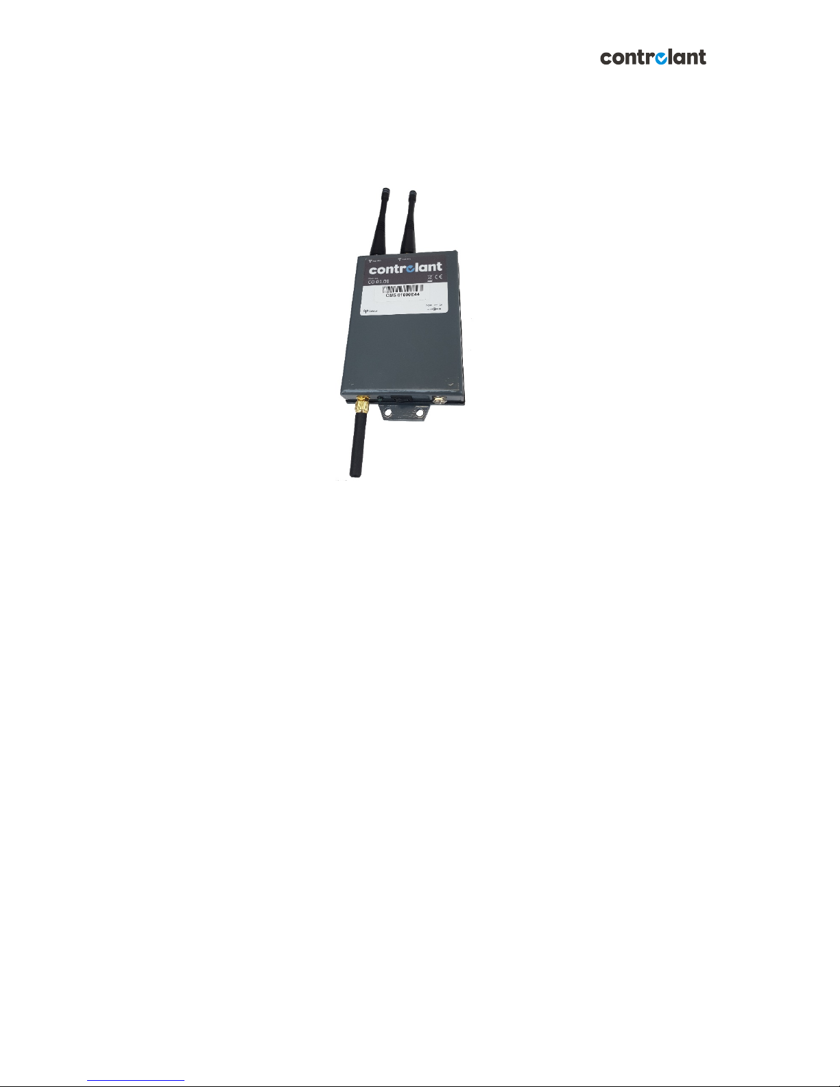
CO 01.01 Gateway .............................................................................................................................................4
Overview........................................................................................................................................................4
Enclosure .......................................................................................................................................................4
Power options................................................................................................................................................4
Power supply .............................................................................................................................................4
Battery pack...............................................................................................................................................4
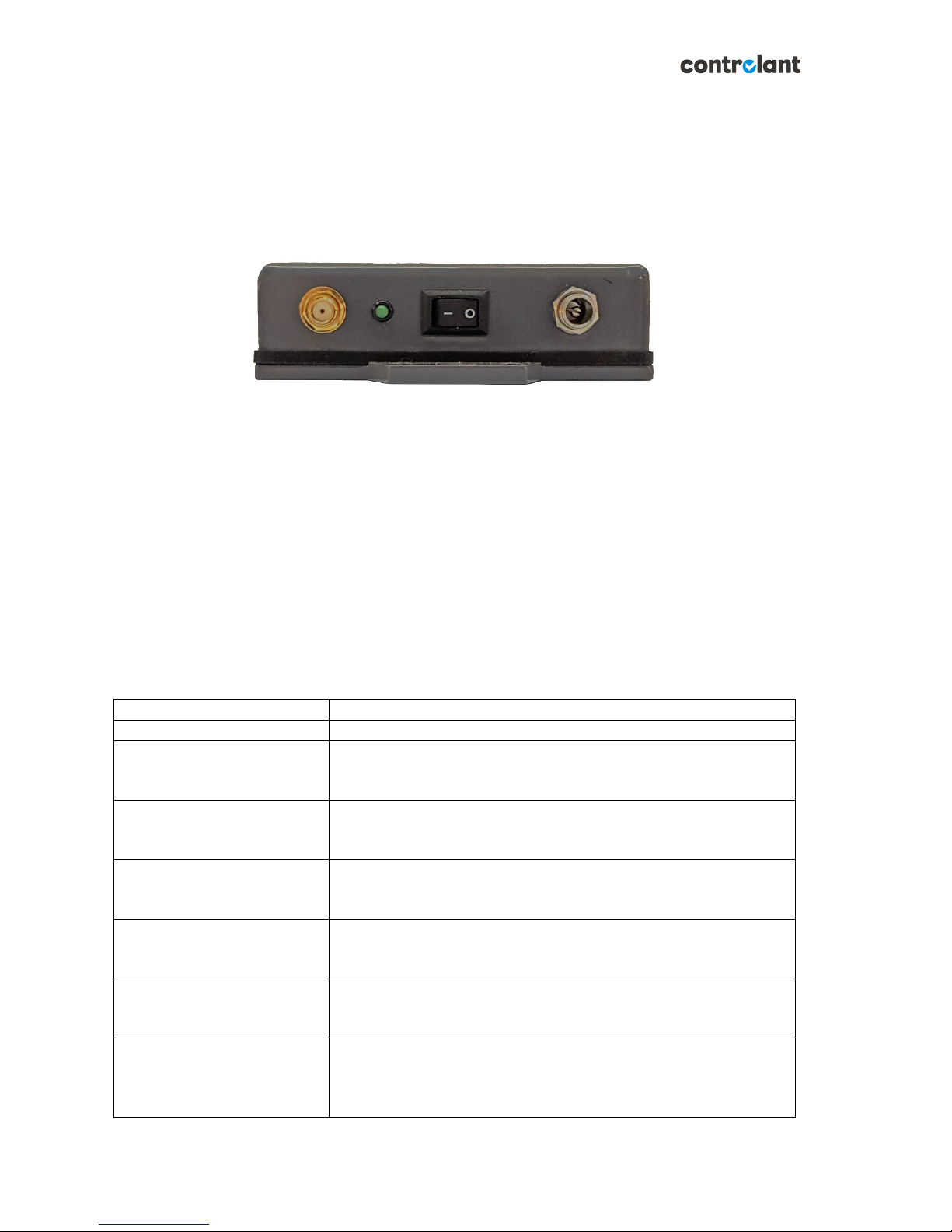
LED, Button and Connectors..........................................................................................................................5
Connection and power-on.........................................................................................................................5
LED indicator light......................................................................................................................................5
On/Off Switch ............................................................................................................................................6
Power connector .......................................................................................................................................6
868MHz Antenna.......................................................................................................................................7
Specifications and ratings..............................................................................................................................7
Environmental range .................................................................................................................................7
Handling and installation...............................................................................................................................7
Mounting orientation ................................................................................................................................7
Antennas....................................................................................................................................................8
Fuse replacement ......................................................................................................................................8
Wireless Connectivity ....................................................................................................................................8
GSM (2G/3G) connectivity.........................................................................................................................9

Version 15 Page 3of 9
General Information
About this guide
This guide describes the features and functions of a Controlant wireless gateway product, CO 01.01
Gateway.
Warranty exception for batteries
Opening the enclosure of the CO 01.01, unless supervised or carried out by service personnel approved by
Controlant, voids all warranty against equipment malfunction.
Controlant CO 01.01 Gateway ships with batteries included. Lithium batteries must be replaced by
Controlant or service personnel approved by Controlant. No warranty is on the behavior of the CO 01.01 in
case of wrong battery installation by non-qualified personnel or in case of usage of batteries which
Controlant does not approve of.
Additional reference material
Additional information on the features and functions of Controlant logger products can be found online at
www.controlant.com and http://confluence.controlant.com/display/CD/User+Documentation
Questions and Technical Support
For technical assistance with your product, contact Controlant Technical Support at +354-517-0630 or

Version 15 Page 4of 9
CO 01.01 Gateway
Overview
Figure 1: C0 01.01 Gateway
The Controlant Gateway, CO 01.01, provides on-line connectivity to multiple Controlant wireless sensors.
The purpose of the Gateway is to gather measurements from multiple sensors in its vicinity and transfer
the data to the Controlant Cloud.
The Gateway can generate and broadcast warnings via e-mail or in a text message (SMS) if measured values
are outside of a user defined range. The Gateway has a LiIon battery which is used as a backup power
source.
Enclosure
The CO 01.01 gateway is offered in a standard aluminum enclosure.
Power options
Power supply
The CO 01.01 Gateway should be DC powered using an external AC/DC adapter supplied with the device,
model SJ-1202000, p/n 120200. Input and output specifications for the adapter:
Input: 100-240VAC 50/60Hz 0.6A
Output: 12VDC 2A
Battery pack
Each CO 01.01 gateway has a built in LiIon battery which will keep the system running in case of external
power failure. The battery should only be replaced by Controlant employees or trained personnel approved
by Controlant. In case of replacement, only batteries approved by Controlant should be used.
CAUTION!

Version 15 Page 5of 9
RISK OF EXPLOSION IF BATTERY IS REPLACED BY AN INCORRECT TYPE. DISPOSE OF USED BATTERIES
ACCORDING TO THE INSTRUCTIONS.
LED, Button and Connectors
Figure 2: GSM antenna connector, LED, on/Off switch and DC power connector for the CO 01.01 gateway.
Connection and power-on
1. Connect the DC plug of the external power supply to the DC power inlet.
2. Turn on the power switch.
3. Wait for the LED indicator light to indicate full operation.
LED indicator light
A green LED indicates the status of the gateway.
Indications:
On/Off
Status of external power
On-line connection status
LED status
Status
Off
The gateway is turned off, or is not operating.
Off, blinking every 0.5
seconds
Operating on battery.
The local network is up and running. No connection to central
database.
Off, blinking every 2 seconds
Operating on battery.
The local network is up and running.
Initializing connection to central database.
Off, blinking every 4 seconds
Operating on battery.
The local network is up and running.
Data is being transferred to the central database.
On, blinking every 0.5 seconds
Charging mode (running on AC adapter).
The gateway is connected to a power source and is being charged.
The local network is up and running. No connection to Cloud.
On, blinking every 2 seconds
Charging mode (running on AC adapter).
The gateway is connected to a power source and is being charged.
The local network is up and running. Initializing connection to Cloud.
On, blinking every 5 seconds
Charging mode (running on AC adapter).
The gateway is connected to a power source and is being charged.
The local network is up and running. Data is being transferred to the
Cloud.

Version 15 Page 6of 9
On/Off Switch
The power switch can turn on the Gateway, set it into hibernation mode and do a hardware reset. The
power switch does not physically disconnect the device from the power source.
The Gateway can send an indication of the current power state before going into hibernation, making
operators able to identify whether the device has been turned off or if there has been a failure in the
system.
On/Off Switch
Behavior
On
Turn on.
When turned on the Gateway wakes up from
hibernation mode.
Full function of the Gateway.
Toggle Off/On
Reset.
While the Gateway is turned on and the on/off
button is toggled to Off and On again it will
resets all sub-systems within the Gateway.
Turn Off (for more than 10 seconds)
Turn off.
If turned Off for more than 10 seconds, the
Gateway goes into hibernation mode.
Power connector
The power connector dimensions are 2.5 x 5.5 x 14 mm as shown in Figure 3 and the polarity is shown in
Figure 4Figure 3: Mechanical drawings of the DC power plug on the CO 01.01.
Figure 3: Mechanical drawings of the DC power plug on the CO 01.01
Figure 4: Polarity of the DC power connector on the CO 01.01

Version 15 Page 7of 9
868MHz Antenna
The CO 01.01 Gateway comes with an 868MHz ¼-wave antenna from Linx Technologies. Peak antenna gain
is 1.6dBi. Impedance of antenna is 50 Ohm.
Figure 5: Antenna pn: ANT-868-CW-QW (with RP-SMA connector).
Consult Controlant for use of an alternate, higher gain, antenna. The use of power amplifiers with the RF
antenna is prohibited.
Specifications and ratings
Environmental range
1. Humidity
a. 0-99% humidity for normal operation.
b. Long term exposure to high levels of humidity may cause unexpected behavior in device.
2. Temperature
a. Recommended operating range is 0°C to 40°C.
b. Absolute minimum and maximum temperatures are -20°C and 60°C. Functionality may be
lost at extreme temperatures.
Handling and installation
The rugged enclosure ensures a good protection against damage. The enclosure does not protect external
components such as antennas, wiring and cables, on/off switch and LED.
The enclosure is designed to withstand spraying water from vertical downward direction (up to 60° from
vertical alignment). Orientation of the gateway should therefore be vertical for maximum protection as
demonstrated in the image to the right.
Cleaning of gateways should be done with neutral soap to prevent rubber sealing, buttons and LEDs from
failing. In case of a need to sanitize or sterilize, use alcohol based compounds and wipe with cloth.
Mounting orientation
The Gateway can be mounted to a surface using screws or bolts. Screws and bolts must be chosen
according to the mounting surface. The Gateway weighs approximately 370 g. Care must be taken that
screws and bolts can handle the weight for the given surface type. Improper mounting and installation can
cause the Gateway to fall from its intended position and cause harm to nearby people. To lower risk of
harm due to improper installation, installation should be carried out by a qualified person.

Version 15 Page 8of 9
Figure 6: CO 0101 Gateway with GSM (2G/3G) antenna pointing down and two 868MHz RF atennnas pointing up. Four mounting
holes are on the Gateway, two on each side.
Antennas
The CO 01.01 Gateway has three antenna connectors. Two are intended for the local 868MHz wireless
communication, and one for GSM (2G/3G) connectivity. Location of each connector is shown in Figure 6.
Antenna connectors are RP-SMA and the GSM antenna connector is SMA.
Fuse replacement
CO 01.01 Gateways come with an internal fuse. The fuse should only be replaced by Controlant or service
personnel approved by Controlant.
Wireless Connectivity
Controlant wireless devices have up to 300m range in open air. The communication frequency channels are
around 868MHz.
The range in open air depends on various factors, including:
1. Mounting and antenna orientation.
2. Proper assembly and selection of antennas.
3. Disturbance on communication frequencies caused by electronic devices, both low and high
current.

Version 15 Page 9of 9
4. Disturbance on communication frequencies caused by other wireless devices.
Wireless range is significantly affected by occluding objects. The indoor range of Controlant devices
depends on various factors, including:
1. Building materials in walls and ceilings.
2. Metal objects occluding the path of the signal.
3. Proper assembly and selection of antennas.
4. Disturbance on communication frequencies caused by electronic devices, both low and high
current.
5. Disturbance on communication frequencies caused by other wireless devices.
GSM (2G/3G) connectivity
The GSM connectivity depends on the network coverage of the network service provider in that area. If the
LED on the gateway indicates that no signal can be found – try to move the gateway to an open location
(window, open air etc.) or contact the network service provider for information about network coverage in
your area.
Other manuals for CO 01.01
1
Table of contents