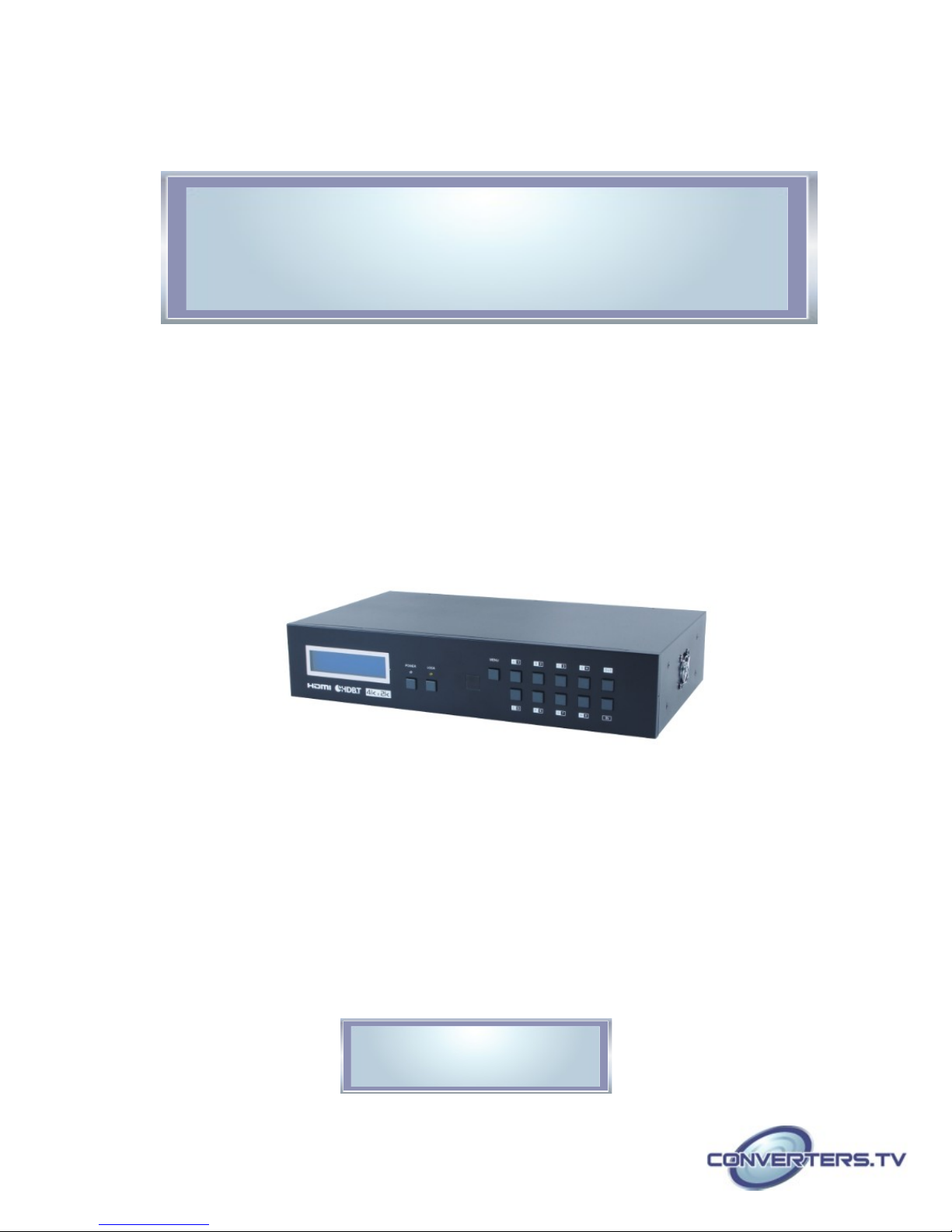
Converters.TV 15437 User manual

4K UHD Matrix 8×8 HDMI over
HDBaseT with 24V PoC - # 154 7
Operation Manual

Introduction
The 4K2K 8 by 8 HDMI Matrix over CAT5e/6/7 supports the trans ission
of video (resolutions up to 4K2K Full HD), ulti-channel digital audio and
control via IR, RS-232, Telnet or Web GUI fro eight high definition
sources to eight outputs over a single CAT5e/6/7 cable (up to 60 ) for each
output.
It supports high resolution digital audio for ats such as LPCM 7.1CH,
Dolby TrueHD, Dolby Digital Plus and DTS-HD Master Audio as well as
3D content that can be displayed when connecting a 3D TV and 3D
source.
Applications
• HDMI Matrix Syste
• Video/TV wall display and control
• Security surveillance and control
• Co ercial advertising, display and control
• University lecture hall, display and control
• Retail sales and de onstration
Features
• HDMI, HDCP 1.1 and DVI co pliant
• Supports resolutions VGA~WUXGA, 4K2K@24/25/30 & YUV_420 and
480i~1080p dependent upon the output display’s EDID settings
• Supports distances up to 60 eters through CAT6/7 cables
• Supports 3D signal display dependent upon the output display EDID
settings
• Supports PoC (Power over Cable) on co patible receivers only
• Supports HDMI input up to 15 eters at 8-bit resolution or 10 eters
at 12-bit resolution
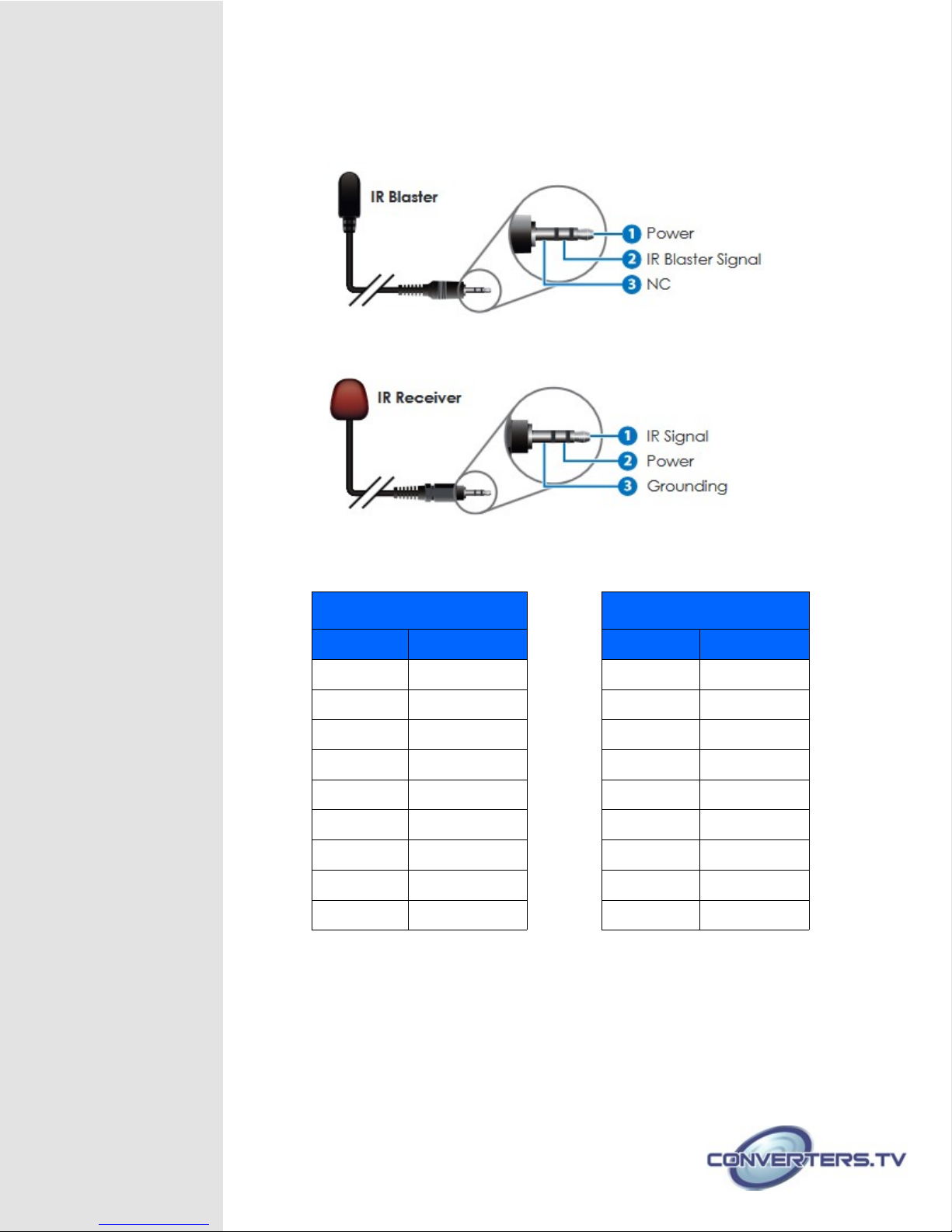
• Supports bi-directional IR fro input and output locations
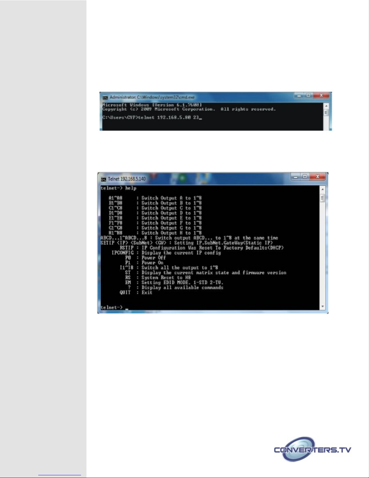
• Supports RS-232, re ote control, on-panel control and IP Control
(Telnet & Web GUI)
• Supports LAN serving function through the LAN port
• 2U size design
• Supports external and internal EDID settings
• Supports LPCM 7.1CH, Dolby TrueHD, Dolby Digital Plus and DTS-HD
Master Audio trans ission
Note:
1. The PoC function is designed for powering compatible receiver units
only—non-PoC receivers will need their own power supply. Receivers
of another brand may not be compatible.
2. o not connect the LAN port to CAT outputs of this device or to CAT
inputs or receiver. oing so may damage the unit.

System
Requirements
• HDMI equipped source devices, connect with HDMI cables or DVI
equipped source, connect with DVI to HDMI cables
• HDMI equipped displays (TVs or onitors) or HDMI equipped AV
receivers, connect with HDMI cables
• Industry standard CAT5e/6/7 cables
• HDBaseT™ Receivers
Operation
Controls and Front Panel
Functions
1. LCM :
Displays the setting infor ation of each input and output setting.
2. POWER:
Press this button to power the device on/off. The LED will illu inate green
when the power is on, red when it is in 'Standby' ode.
3. LOCK:
Press this button for 3 seconds to lock all the buttons on the panel; press
again for 3 seconds to unlock. The LED will illu inate green when locked.
4. IR:
IR Receiver window (accepts the re ote control signal of this device only).
5. MENU:
Press this button to access the LCM enu syste , fro here EDID
settings can be anaged and IP syste settings are displayed.
6. 1~8/A~H and In/Out:
Press the Out or In button to select the output or input ode and then
press the required nu ber button to ake the selection accordingly.
For exa ple, if outputs A~D need to be set to input 1 and outputs
E~H need to be set to input 2, then the following sequence of
button presses need to be perfor ed:
Press: Out →A→B→C→D→In→1→Menu,
and then press: Out→E→F→G→H→In→2→Menu.
Note:
If the menu button is not pressed the selection will not be
changed.

Rear Panel
1. LAN:
Connect to an active network for LAN serving and Telnet and Web GUI
control (refer to Sections on Telnet and Web GUI).
When the Matrix or any co patible LAN equipped receivers are connected
to a network, this allows the network access (including internet access if
available) to be shared between the Matrix and all connected receivers.
Connect any Ethernet equipped device e.g. a S art TV or ga es console
to the LAN port of a receiver for that device to share the network/internet
access.
Warning: Please do not connect ore than one active Ethernet link within
the Matrix syste .
2. RS-232:
Connect to a PC or control syste with D-Sub 9-pin cable for the
trans ission of RS-232 co ands.
3. ALL IR OU :
Connect to the IR blaster for IR signal trans ission to the source side.
Place the IR blaster in direct line-of-sight of the equip ent to be controlled
for it will blaster out all signal received fro the IR IN at the receiver sides.
4. ALL IR IN:
Connect to the IR extender for IR signal reception. Ensure that re ote
being used is within the direct line-of-sight of the IR extender for it will send
out the signal to all receiver's IR OUT.
5. SERVICE:
Manufacturer use only.
6. IR OU 1~8:
Connect to the IR blasters for IR signal trans ission.
Place the IR blaster in direct line-of-sight of the equip ent to be controlled
for it will blaster out the IR signal received fro the receiver side chosen by
input selection.
7. IR IN 1~8:
Connect to the IR extenders for IR signal reception. Ensure that re ote
being used is within the direct line-of-sight of the IR extender for it will send
out the IR signal to the selected receiver's IR OUT.
8. CA 5e/6/7 OU 1~8:

Connect fro these CAT outputs to the CAT input port of the receiver units
with a single CAT5e/6/7 cable for HDMI Audio/Video and IR/RS-232 control
signal trans ission.
9.HDMI IN 1~8:
Connect to the HDMI input source devices such as a DVD player or a Set-
top Box with HDMI cable or DVI to HDMI cable.
10. DC 24V MAIN POWER:
Plug the 24 V DC power supply into the unit and connect the adapter to an
AC outlet.
11. PoC 24V:
Plug the 24 V PoC power supply into the unit and connect the adapter to an
AC outlet. This unit will power PoC (Power over Cable) capable receiver
units.
Side Panel
1. Fan Ventilator:
These are air ventilation areas, DO NO block these areas or cover it with
any object. Please allow adequate space
around the unit for air circulation
Remote Control
1. POWER: Press this button to
switch on the device or set it to
standby ode.
2. IN: Input ports selection 1~8.
3. OU : Output ports selection A~H

IR Cable
Pin Assignment
D-Sub 9-Pin
Assignment
HDBaseT 8x8 Matrix Remote Control
Pin Assignment Pin Assignment
1 N/C 1 N/C
2 Tx 2 Rx
3 Rx ► 3 Tx
4 N/C 4 N/C
5 GND 5 GND
6 N/C ◄ 6 N/C
7 N/C 7 N/C
8 N/C 8 N/C
9 N/C 9 N/C
Baud Rate: 19200 bps
Data bit: 8 bits
Parity: None
Stop Bit: 1
Flow Control: None

RS-2 2 and Telnet
Commands
Command Description
A1~A8 Switch Output A t 1~8
B1~B8 Switch Output B t 1~8
C1~C8 Switch Output C t 1~8
D1~D8 Switch Output D t 1~8
E1~E8 Switch Output E t 1~8
F1~F8 Switch Output F t 1~8
G1~G8 Switch Output G t 1~8
H1~H8 Switch Output H t 1~8
ABCD...1~ABCD...8 Switch Output A B C D... to 1~8 at
the sa e ti e
SETIP <IP> <SubNet> <GW> Setting IP. SubNet. GateWay (Static
IP)
RSTIP IP Configuration Was Reset To
Factory Defaults <DHCP>
IPCONFIG Display the current IP c nfig
P0 Power OFF
P1 Power ON
I1~I8 Switch all the Output to 1~8
ST Display the current atrix status and
F/W version
RS Syste Reset to A1, B2, C3, D4, E5,
F6, G7, H8
EM Setting EDID MODE. 1-STD 2-TV
UARTBAUD1~8 Set output A~D’s uart baud rate fro
1~6
1: 9600bps
2: 14400bps
3: 19200bps
4: 38400bps
5: 57600bps
6: 115200bps
UARTSW1~8 Switch output’s UARTto A~H and
allow Matrix to send co ands to
Receiver's connected RS-232
device.

UARTSW0 Switch output's UART to MCU.
Restoring RS-232 control to the
Receiver output back to Matrix.
UARTBAUD? Display all the utputs UART baud
UARTSW? Display the UART switching state
? Display all the available c mmands
Quit Exit(f r telnet nly)
Note:
Any commands will not be executed unless followed by a carriage return.
Commands are case insensitive.
Telnet Control
Before atte pting to use the telnet control, please ensure that both the Matrix
(via the 'LAN port) and the PC/Laptop are connected to the active networks.
To access the telnet control in Windows 7, click on the 'Start' enu and type
"c d" in the Search field then press enter.
Under Windows XP go to the 'Start' enu and click on "Run", type "c d" with
then press enter.
Under Mac OS X, go to Go→Applications→Utilities→Ter inal
See below for reference.

Once in the co and line interface (CLI) type "telnet", the IP address of the unit
you wish to control and "23", then hit enter.
Note:
The IP address of the Matrix can be displayed on the device's LCM monitor by
pressing the Menu button twice/three times.
This will bring us into the device which we wish to control. Type "HELP" to list the
available co ands.
Type “IPCONFIG” To show all IP configurations. To reset the IP, type “RSTIP”
and to use a set static IP, type ”SETIP” (For a full list of co ands, see Telnet
Co ands Section).
Note:
Any commands will not be executed unless followed by a carriage return.
Commands are not case-sensitive. If the IP is changed then the IP Address
required for Telnet access will also change accordingly.

Web GUI Control
On a PC/Laptop that is connected to the sa e active network as the Matrix, open
a web browser and type device's IP address on the web address entry bar. The
browser will display the device's status, control and User setting pages.
Click on the 'Control' tab to control power, input/output ports, EDID and reset
ode.
Clicking on the 'User Setting' tab allows you to reset the IP configuration. The
syste will ask for a reboot of the device every ti e any of the settings are
changed. The IP address needed to access the Web GUI control will also need
to be changed accordingly on the web address entry bar.

Specifications
Video Bandwidth 300 MHz/9 Gbps
Input Ports 8×HDMI, 9×IR Extender, 1×RS-232, 1xLAN,
1×Mini USB-B type (for fir ware update only)
Output Ports 8×CAT5e/6/7, 9×IR
Power Supply 24 V/6.25 A DC (US/EU standards, CE/FCC/
UL certified)
ESD Protection Hu an Body odel:
± 8kV (air-gap discharge)
± 4kV (contact discharge)
Dimensions 438 (W)×249 (D)×93 (H)
Weight 4402g
Chassis Material Metal
Silkscreen Color Black
Operating emperature 0 ºC~40 ºC/32 ºF~104 ºF
Storage temperature −20 ºC~60 ºC/−4 ºF~140 ºF
Relative Humidity 20~90% RH (no condensation)
Power Consumption 65 W Tx (Main), 56W Rx (PoE)

Connection Diagram
Other Converters.TV Matrix Switcher manuals