Converters.TV 986 User manual

8×8 HDMI over Single CAT5e/6/7
Matrix with PoE ID# 986
Operation Manual

Introduction
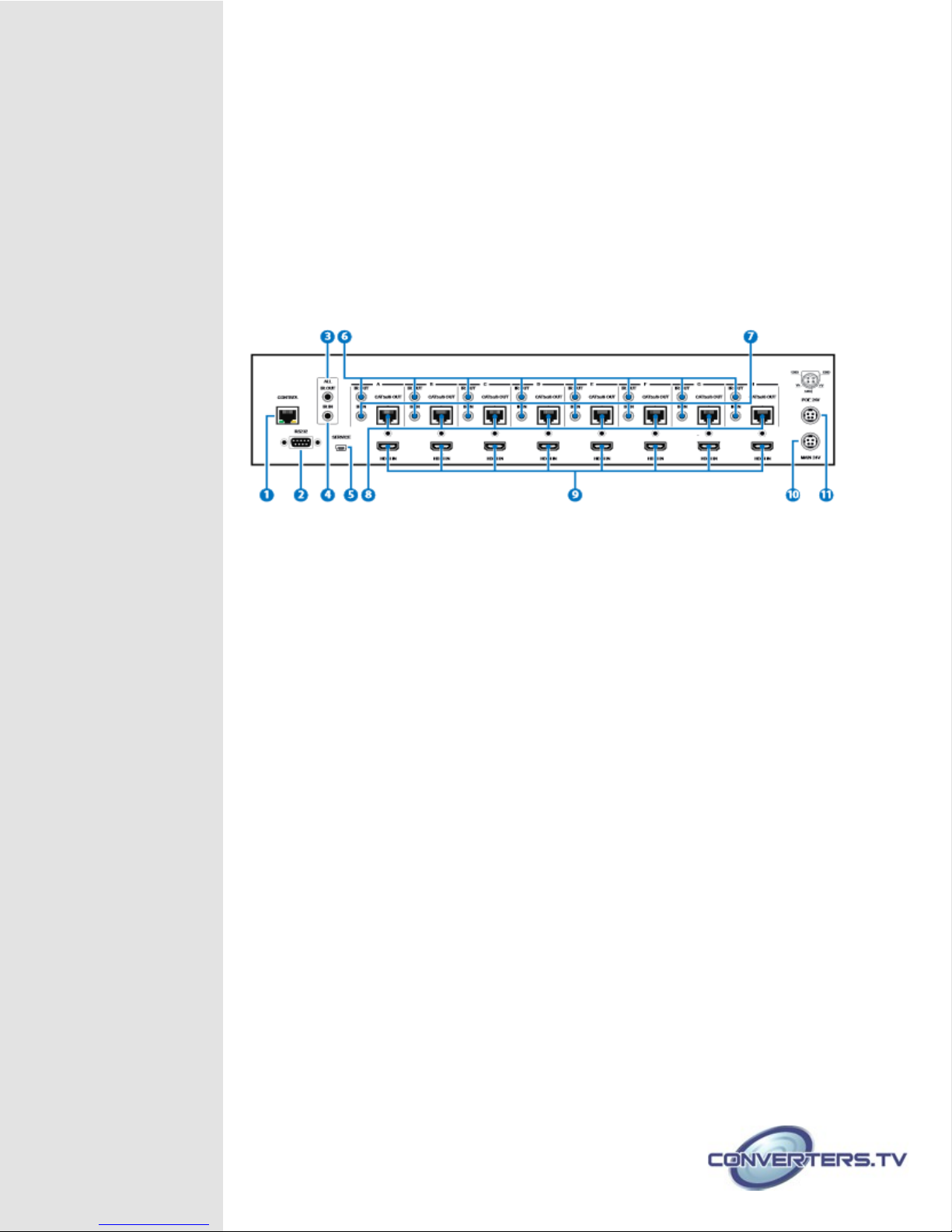
The HDBaseT™ 8 by 8 HDMI Matrix over CAT5e/6/7 supports the
transmission o video (resolutions up to 1080p Full HD and
1920×1200@60Hz) and multi-channel digital audio rom eight high de inition
sources to eight outputs over a single CAT5e/6/7 cable (up to 100m) or
each output. It supports high resolution digital audio ormats such as LPCM
7.1CH, Dolby TrueHD, Dolby Digital Plus and DTS-HD Master Audio as well
as 3D content that can be displayed when connecting a 3DTV and 3D
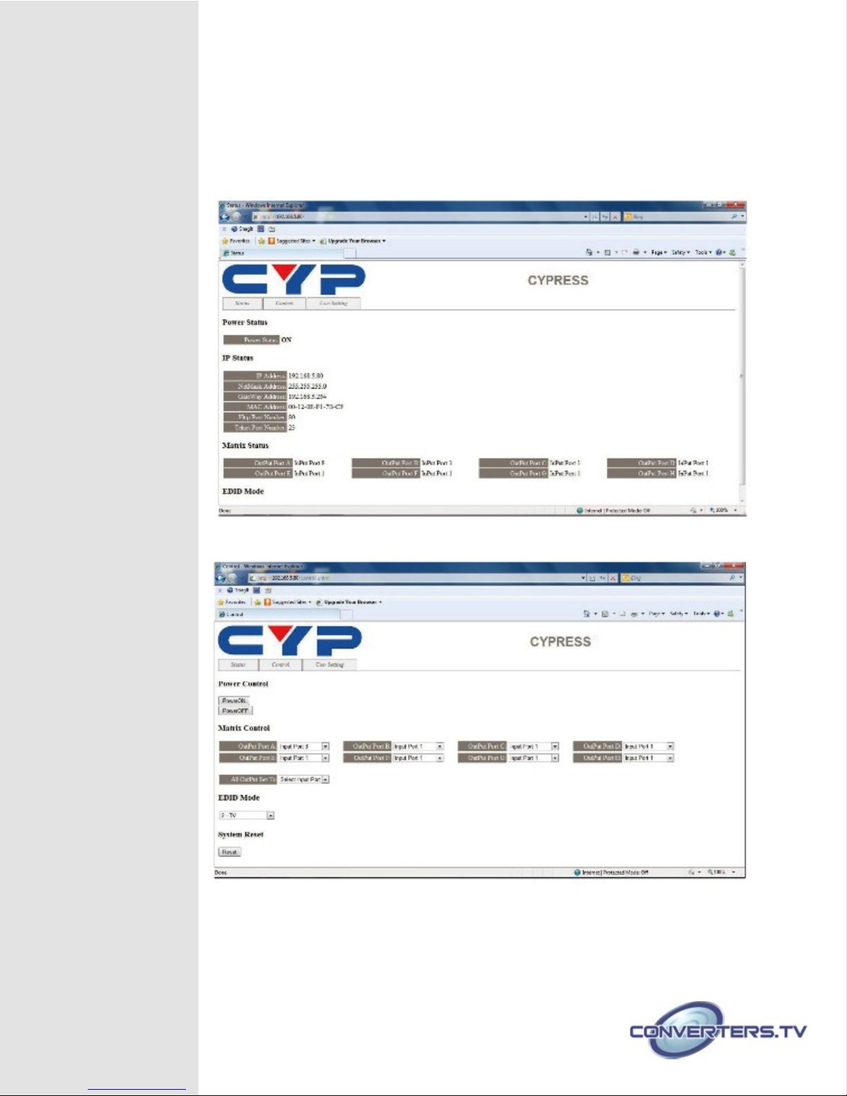
source. The matrix can be controlled via IR, RS-232, Telnet or Web GUI.
Power over Ethernet (PoE) support means that compatible receivers do not
need their own seperate power supplies, allowing or greater lexibility in
installations.
Features
•HDMI, HDCP1.1 and DVI compliant
•Supports HDMI 3D eatures
•Supports resolutions VGA~WUXGA and 480i~1080p dependent
upon the output display’s EDID settings
•Supports 3D signal display dependent upon the output display EDID
settings
•Supports PoE (Power over Ethernet) on compatible receivers only
•Supports HDMI input up to 15 meters at 8-bit resolution or 10 meters
at 12-bit resolution
•Supports bi-directional IR to and rom input and output locations
•Supports control via RS-232, IR remote, on-panel buttons and IP
(Telnet & Web GUI)
•2U size design
•Supports external and internal EDID settings
•Supports LPCM 7.1CH, Dolby TrueHD, Dolby Digital Plus and DTS-
HD
•Master Audio transmission
Note:
1. The PoE unction is designed or powering compatible receiver
units only—non-PoE receivers will need their own power supply.
Receivers o another brand may not be compatible.
.
2. Do not connect the CONTROL port to CAT outputs o this device
or to CAT inputs or receiver. Doing so may demage the unit.
Applications
●HDMI Matrix System
●Video/TV wall display and control
●Security surveillance and control
●Commercial advertising, display and control
●University lecture hall, display and control
●Retail sales and demonstration

System Requirements
•HDMI equipped source devices, connect with HDMI cables or
DVI equipped source, connect with DVI to HDMI cables
•HDMI equipped displays (TVs or monitors) or HDMI equipped
AV receivers, connected with HDMI cables
•Industry standard CAT5e/6/7 cables
•HDBaseT™ Receivers (CH-506RX, CH-507RX or CH-1109RX)
Operation ontrols
and Functions
Front Panel
1 LCM:
Displays the setting in ormation o each input and output
setting.
2 POWER:
Press this button to power the device on/o . The LED will
illuminate green when the power is on, red when it is in 'Standby'
mode.
3 LOCK:
Press this button to lock all the buttons on the panel; press
again to unlock. The LED will illuminate green when locked.
4 IR:
IR Receiver window (accepts the remote control signal o this
device only) with IR requency o 38
kHz.
5 MENU:
Press this button to access the LCM menu system, rom
here EDID settings can be managed and IP system settings are
displayed.
6 1~8/A~H and OUT/IN:
Press the OUT or IN button to select the
output or input mode and then press the required number button
to make the selection accordingly.
For example, i outputs A~D need to be set to input 1 and outputs

E~H need to be set to input 2, then the ollowing sequence o
button presses need to be per ormed:
Press: OUT →A→B→C→D→IN→1→MENU,
and then press: OUT→E→F→G→H→IN→2→MENU.
Note: I the MENU button is not pressed the selection will not be
changed
Back Panel
1 CONTROL:
This port is the link or Telnet or Web GUI controls, connect
to an active Ethernet link with an RJ45 terminated cable ( or urther
details on IP control, please re er to sections 6.8 & 6.9).
Warning: Please do not connect this port directly to the PC/Laptop as the
Telnet unction will not work.
2 RS-232:
Connect to a PC or control system with D-Sub 9-pin cable
or control o the matrix via RS-232 commands (please re er to
Section 6.7 or a list o commands).
3 ALL IR OUT:
Connect to the IR blaster or IR signal transmission to the
source devices. Place the IR blaster in direct line-o -sight o the
equipment to be controlled. All signals received rom the display
side will be relayed to the source devices.
4 ALL IR IN:
Connect to the IR extender or IR signal reception. Ensure
that the remote being used is within the direct line-o -sight o the IR
extender. It will transmit all signals received through the IR ALL OUT.
5 SERVICE:
Manu acturer use only.
6 IR OUT A~H:
Connect to the IR blasters or IR signal transmission.
Place the IR blaster in direct line-o -sight o the equipment to be
controlled. It will transmit the IR signal received rom the receiver
side according to the selected input.
7 IR IN 1~8:
Connect to the IR extenders or IR signal reception. Ensure

that the remote being used is within the direct line-o -sight o the
IR extender. It will send out the IR signal received to the selected IR
OUT (A-H).
8 CAT5 /6/7 OUT A~H:
Connect the CAT outputs to the CAT input port
o the receiver units with a single CAT5e/6/7 cable or HDMI Audio/
Video and IR control signal transmission.
Warning: Pl as do not conn ct th CAT5 /6/7 outputs to th
r c iv r's LAN port
9 HDMI IN 1~8:
Connect to the HDMI source devices such as a DVD
player or a Set-top Box with HDMI cables or DVI to HDMI cables.
10 DC 24V:
Connect the 24 V DC power supply to the unit and plug the
adaptor into an AC outlet.
11 PoE 24V:
Connect the 24V PoE power supply into the unit and plug the adaptor
into an AC outlet. This unit will mainly power PoE (Power over Ethernet)
capable receiver units.
Side Panel
1 Fan V ntilator:
These are air ventilation areas, DO NOT block these
areas or cover it with any object. Please allow adequate space
around the unit or air circulation.

Remote ontrol
1 POWER:
Press this button to switch
the device 'ON' or set it to standby
mode.
2 IN:
Input selection 1~8.
3 OUT:
Output selection A~H.
Note: When the IR remote is used
in the Output Zone the user only
needs to select the desired input
(1~8)
IR able PIN
Assignments

RS-232 Pin
Assignment
HDMI MATRIX REMOTE ONTROL ONSOLE
PIN A ignment PIN A ignment
1 NC 1 NC
2 Tx 2 Rx
3 Rx → 3 Tx
4 NC 4 NC
5 GND ← 5 GND
6 NC 6 NC
7 NC 7 NC
8 NC 8 NC
9 NC 9 NC
Baud Rate: 19200 bps
Data Bit: 8-bit
Parity: None
Stop Bit: 1-bit
Flow Control: None
RS-232 Telnet
ommands
OMMAND DES RIPTION
A1~A8 Switch Output A to 1~8
B1~B8 Switch Output B to 1~8
C1~C8 Switch Output C to 1~8
D1~D8 Switch Output D to 1~8
E1~E8 Switch Output E to 1~8
F1~F8 Switch Output F to 1~8
G1~G8 Switch Output G to 1~8
H1~H8 Switch Output H to 1~8
ABCD...1~ABCD...8 Switch Output ABCD... to 1~8 at the
ame time
SETIP <IP> <SubNet> <GW> Setting IP. SubNet. GateWay<Static IP>
RSTIP IP configuration wa re et to factory
default <DHCP>
IPCONFIG Di play the current IP config

P0 Power Off
P1 Power On
I1~I8 Switch all the output to 1~8
ST Di play the current matrix tate and
firmware ver ion
RS Sy tem Re et to H8
EM Setting EDID MODE. 1-STD 2-TV.
? Di play all available command
QUIT Exit (Telnet only)
Note:
1.Commands will not be executed unless ollowed by a carriage
return. Commands are case-insensitive.
2.When the Telnet connection is idle or 10 minutes it will be
automatically disconnected.
3.The TV EDID setting will always ollow output port 1's EDID setting
regardless o the output change.
4.EDID setting switching will execute immediately.
Telnet ontrol
Be ore attempting to use the telnet control, please ensure that both
the Matrix (via the 'LAN /CONTROL' port) and the PC/Laptop are
connected to the same active networks.
To access the telnet control in Windows 7, click on the 'Start' menu
and type "cmd" in the Search ield then press enter.
Under Windows XP go to the 'Start' menu and click on "Run", type
"cmd" with then press enter.
Under Mac OS X, go to Go→Applications→Utilities→Terminal
See below or re erence.

Once in the command line inter ace (CLI) type "telnet", then the IP
address o the unit and "23", then hit enter.
Note: The IP address o the Matrix can be displayed on the device's
LCM monitor by pressing the Menu button twice.
This will bring us into the device which we wish to control. Type "HELP"
to list the available commands.
Type “IPCONFIG” To show all IP configurations. To reset the IP, type
“RSTIP” and to use a set static IP, type ”SETIP” (For a ull list o
commands, see Page 7).
Note: Commands will not be executed unless ollowed by a carriage
return. Commands are not case-sensitive. I the unit's IP is changed
then the IP Address required or Telnet access will also change
accordingly.

Web GUI ontrol
On a PC/Laptop that is connected to the same active network as the Matrix,
open a web browser and type the device's IP address on the web address
entry bar. The browser will display the device's status, control and User
setting pages.
Click on the 'Control' tab to control power, input/output ports, EDID and reset
mode.
Clicking on the 'User Setting' tab allows you to reset the IP con iguration.
The system will ask or a reboot o the device when any o the settings are
changed. The IP address needed to access the Web GUI control will also
need to be changed accordingly on the web address entry bar.

AT5e/6/7 able
Specification
ABLE
TYPE
RANGE PIXEL
LO K
RATE
VIDEO
DATA
RATE
SUPPORTED
VIDEO
CAT5e/6/7 100m ≤225 MHz ≤5.3 Gbp
(HD Video)
Up to 1080p, 60 Hz,
36 bit , 3D (data
rate lower than 5.3
Gbp or below 225
MHz TMDS clock).
70m >225 MHz > 5.3 Gbp
(Ultra HD
Video)
4K×2K, 30
Hz video
format

Specifications
Video Bandwidth 225 MHz/6.75 Gbp
Input Ports 8×HDMI, 9×IR Extender, 1×RS-232, 1×RJ-
45 (Control), 1×Mini USB Type B (For
firmware updated only)
Output Ports 8×CAT5e/6/7, 9×IR Bla ter
IR Frequency 30~50 kHz
Supported Resolutions HDTV: 480i~1080p@50/60 & 1080p@24
PC: VGA~WXGA
HDMI Input able Length 15m (1080p@8-bit)
10m (1080p@12-bit)
Audio Sampling Rate Up to 192 kHz
ESD Protection Human-body Model:
± 8kV (Air-gap di charge)
± 4kV (Contact di charge)
Power Supply 2x24V/6.25A DC (US/EU tandard ,
CE/FCC/UL certified)
Dimensions 438mm (W)×255mm (D)×93mm (H)
Weight 4458g
hassis Material Metal
olor Black
Operating Temperature 0 ºC~40 ºC/32 ºF~104 ºF
Storage Temperature −20 ºC~60 ºC/−4 ºF~140 ºF
Relative Humidity 20~90% RH (non-conden ing)
Power onsumption 64W/TX (Main), 56W/RX (PoE)

Table of contents
Other Converters.TV Matrix Switcher manuals