Converters.TV ID 859 User manual

HD/SD Digital AV Mixer
- ID# 859
Operation Manual

Introduction
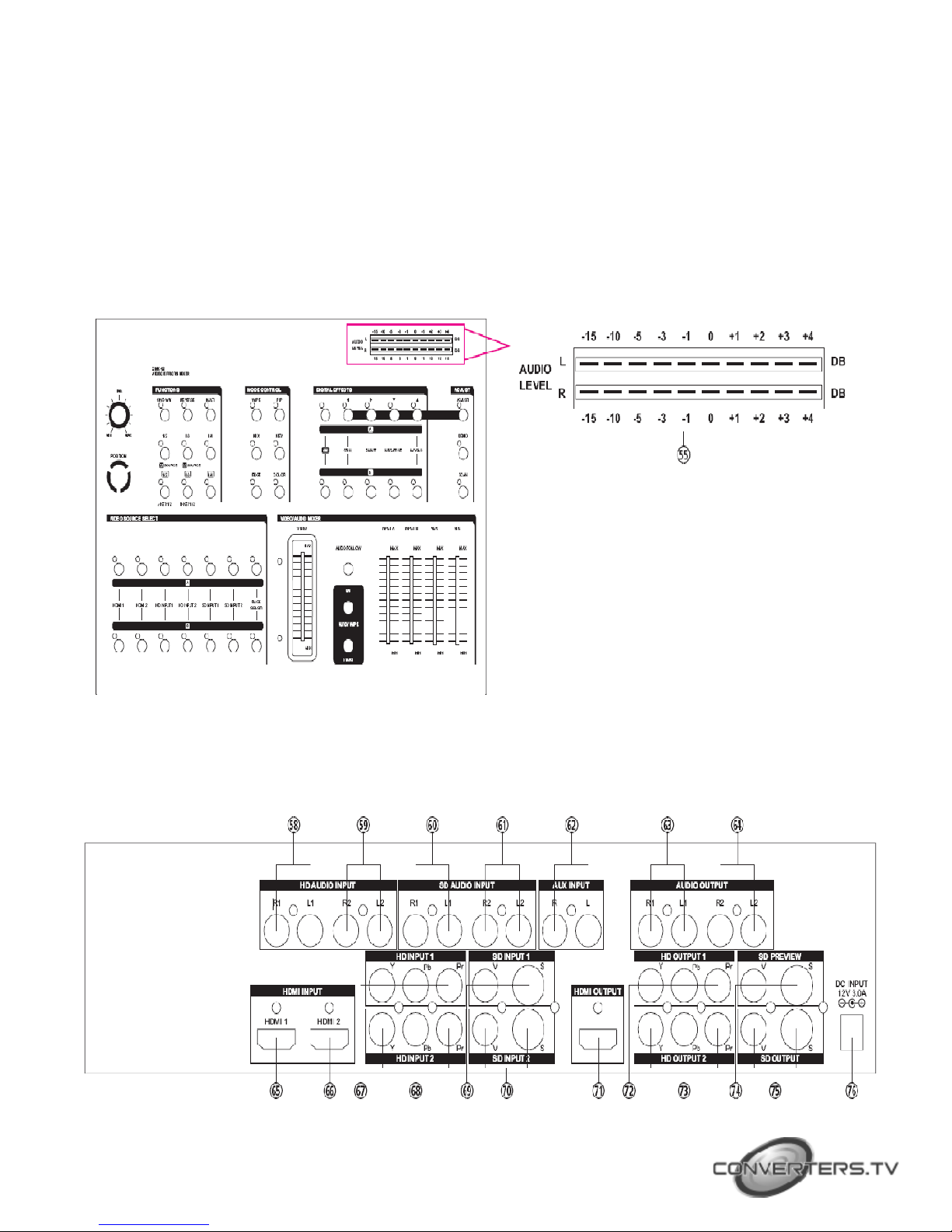
This high definition HD/SD digital AV Mixer. Each input BUS supports 6 inputs 2
x HDMI, 2 x Component, 2 x S-Video and Composite video) and also
Background Color for special efficiency. The output supports 1 x HDMI, 2 x
Component, 2 x S-Video and Composite video, it also supports position
adjustment and recording.
The output supports HD/SD resolution for example, NTSC, NTSC-4.43, PAL, PAL-M,
PAN-N, SECAM, 480p, 576p, 720p 50/60, 1080i 50/60.
The output resolution can auto adjust to consistency resolution, please refer to the
diagram on the right side.
Features
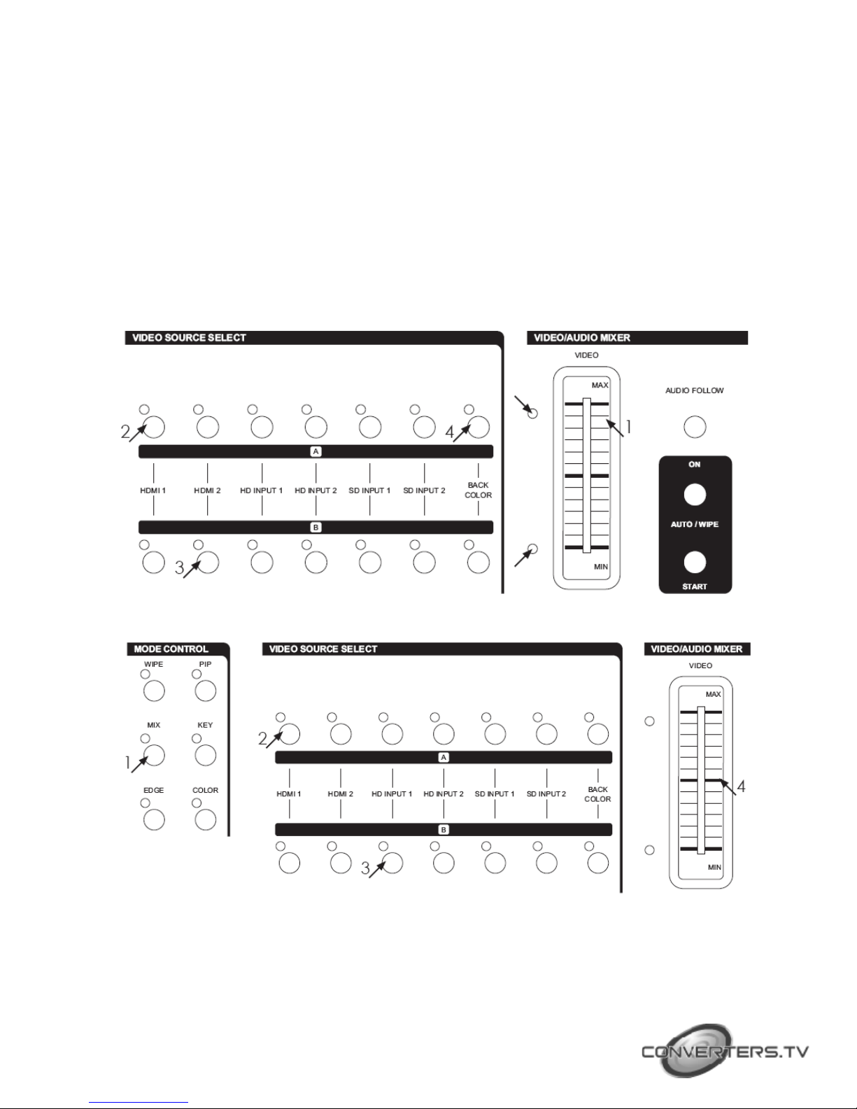
●Selective size and position for digital effects area and PIP windows.
●Automatic fade and wipe with speed preset control.
●Digital effects- Still,Mosaic,Paint,Negative.
●96 wipe patterns.
●Chroma key & Luminance key.
●High Picture Quality.
●3x8 back color.
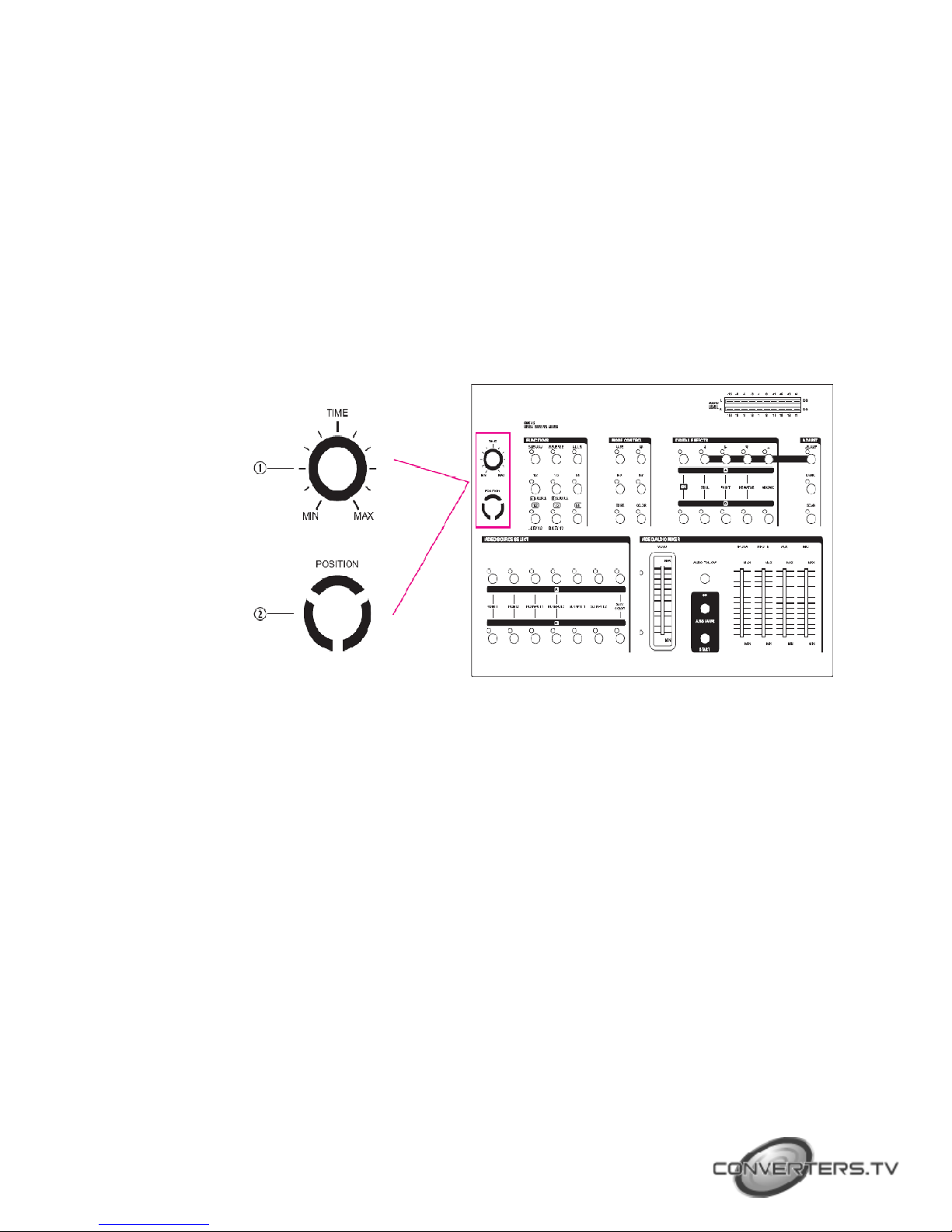
●Joystick control for digital effect position.
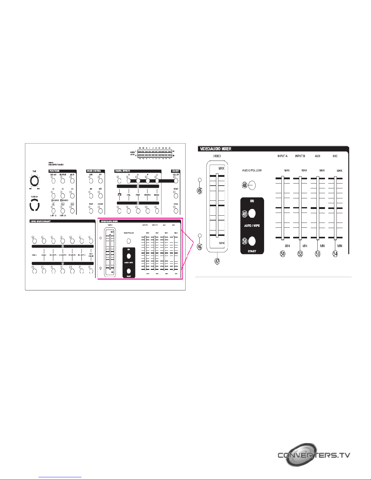
●Fade control for Video and Audio.
●Video and Audio mixing.
●Two HDMI source inputs.
●Two Component source inputs.
●Two Composite and S-Video source inputs.
●One HDMI recording outputs.
●Two Component recording outputs.
●One Composite and S-Video recording outputs.
●One Composite and S-Video preview outputs OSD).
●Auxiliary audio input.
●Microphone input and headphone output.

●Picture in Picture control. 3 window sizes)
●Each A/B BUS can adjust the Contrast / Brightness / Color / HUE / Detail &
Aspect Ration.
●Supports Lip-Sync delay up to 170ms.
●Composite supports 3D comb filter and YC separation.
●Motion and Edge Adaptive De-interlacing.
●Note: When receiving content that has HDCP encryption there will be no video
output except for HDMI output port.
Major Operating Controls and Their Functions
n POSITION/TIME
1. Time Control
For adjusting the transition time of Auto Fade function and Auto take
function.
2. oystick control
This joystick control has two functions controls the position of the Square
wipe pattern and P-IN-P picture.

n FUNCTIONS
3. One-way wipe button.
4. Reverse wipe button.
5. Multiple wipe button.
6. Straight wipe button.
7. Split wipe button.
8. Corner wipe button.
9. Diagonal wipe button.
10. Triangle wipe button.
11. Square wipe button.
n MODE CONTROL

12. Wipe button
For selecting the wipe effect.
13. PIP button
Picture in picture mode can be selected by pressing this button.
14. Mix(Fade) button
Press this button to select the fade In/Out mode.
15. KEY button
This button allows you to tune in a best performance point for the blue key
and luma key effects.
16. EDGE button
Press WIPE button, can select sharp edge / soft edge or color edge.
18. COLOR button
Press color edge, can select eight different color of frame.
n DIGITAL EFFECTS
18. A-bus digital effect ON button.
19. A-bus Still button and osd left adjust.
20. A-bus Paint button and osd right adjust.
21. A-bus Negative button and osd up adjust.
22. A-bus Mosaic button and osd down adjust.
23. B-bus digital effect ON button.
24. B-bus Still button.
25. B-bus Paint button.
26. B-bus Negative button.
27. B-bus Mosaic button.

n AD UST
28. Adjust button
When LED switched off, the SDP review output side will show AB-bus / output source
and output format. When LED illuminate, the suer can press 19, 20, 21 and 22 buttons to
adjust the values.
29. DEMO button
When LED illuminate, the auto DEMO will switch to ON and the system will auto
sequence Demo 96 wipe patterns, press 1 TIME button to adjust the auto
sequence.
30. SCAN button
Press SCAN button for 3 seconds, the system will enter into SCAN function and
will SCAN the input ports from 1 to 6 and record each port's format to the system.
n VIDEO SOURCE SELECT

31-38. Used to select Source1,HDMI1.
32-39. Used to select Source2,HDMI2.
33-40. Used to select Source3,HD input 1.
34-41. Used to select Source4,HD input 2.
35-42. Used to select Source5,SD input 1. When connecting both S-Video and CV at
the same the time S-Video will be the first priority source to be display.
36-43. Used to select Source5,SD input 2. When connecting both S-Video and Video
at the same the time S-Video will be the first priority source to be display.
37. A-bus back color select, can select one out of eight colors.
44. B-bus back color select, can select one out of eight colors.
n VIDEO/AUDIO MIXER
45. A-bus LED indicator.
46. B-bus LED indicator.
When VIDEO slider move to A-bus the A-bus's LED will illuminate and move the slider to
B-bus the B-bus's LED will illuminate. When slider move in between A-bus
and B-bus the two LED will alternate illuminatd. When in Auto/Wipe the status
will be the same condition.
47. VIDEO slide.
Wipe, PIP and Key effects could be controlled by this Video slide which moves
A/B bus outputs horizontally or vertically.
48. AUDIO FOLLOW.
When turn on the Audio Follow A/B bus's sound indicator will follow the VIDEO slider
movement. When turn off the Audio Follow, the audio indicator
will become independent to adjust from 51and 52.
49. AUTO/WIPE.
AUTO FADE/WIPE can be performed with START 50 button when the button 49 is set to
ON.
50. START button.

Automatic MIX and WIPE operation can be performed by pressing the START button.
Transition time can be adjusted via TIME 1 . When transition time lapsed, the LED goes
off.
51. INPUT A:Controls the audio level of the input A.
52. INPUT B:Controls the audio level of the input B.
53. AUX:Controls the audio level of the Auxiliary input.
54. MIC:Controls the audio level of the Microphone input.
n AUDIO LEVEL
55. Audio level indicator.(Audio level)
This indicator shows the audio output level of REC out 1 and REC out 2.
n REAR PANEL

58. Source 3 HD audio input 1.
59. Source 4 HD audio input 2.
60. Source 5 SD audio input 1.
61. Source 6 SD audio input 2.
62. Auxiliary Audio input ack.
63. Recording out 1 Audio output ack.
64. Recording out 2 Audio output ack.
65. Source 1 HDMI input 1.
66. Source 2 HDMI input 2.
67. Source 3 HD Y-PB-PR Video input 1.
68. Source 4 HD Y-PB-PR Video input 2.
69. Source 5 SD Video and YC input 1.
70.Source 6 SD Video and YC input 2.
71. HDMI output for monitor.
72. Recording out 1 HD Y-PB-PR Video output jack.
73. Recording out 2 HD Y-PB-PR Video output jack.
74. SD PREVIEW out(OSD) Video and YC output jack.
75. SD Recording out Video and YC output jack.
76. DC INPUT 12V 2.0A.
Basic Operations
Press the power switch on the rear panel to the ON Position. The LED's on the operation
panel light up and the unit is now in inital mode for operation.

A. Input signal selection and Back color Selection
1. Slide the Video slide 47 to the A-bus position.
A-bus LED 45 will illuminate, B-bus LED will turn off.
2. Press any of the Source 1 to Source 6 and Back color button.
You will see the corresponding picture on the screen.
3. Press a Back Color button to select the back color you need.
Any of the 8 Back Colors-Blue/Red/Magenta/Green/Cyan/Yellow/White/Black.
can be selected by repeatedly pressing the Back color selection button 37.
4. The same procedures apply to the B-bus.
* When the selected input source is not connected with source input or HDCP
protection, the image will show with Blue screen.
B. VIDEO MIX
Reset the operation panel to initial mode:
1. Press the MIX button 1 4 .
2. Press one of the A-bus selection button.
3. Press one of the B-bus selection button.
4. Mix effect could be controlled b Video slide 44 which sliding A to B or B to A.

C. VIDEO WIPE
Reset the operation panel to initial mode:
1. Press the WIPE button 1 2 .
2. Press one of the A-bus selection button.
3. Press one of the B-bus selection button.
4. WIPE effect could be controlled b Video slide 4 7 which moves A/B bus outputs Horizontall or verticall .
5. Press 1 6 EDGE button to select frame sharp edge / soft edge / color edge.
6. When frame color is "color edge, press 1 7 COLOR button to select one out of eight colors to displa .
n WIPE PATTERN Selection:
Six wipe modes can be selected as follows:
1. Press the straight wipe button 6 repeatedl , Four patterns are
available.

2. Press the corner wipe button 7
repeatedly, Four patterns are available.
5. Press the split wipe button 1 0 repeatedl ,
Four patterns are available.
3. Press the diagonal wipe button 8
repeatedl , Four patterns are available.
6. Press the square wipe button 1 1
repeatedl . Four patterns below are available. Each
pattern position in this section could be set b
jo stick 2.
4. Press the triangle wipe button 9
repeatedl , Four patterns are available.

n MULTIPLE PATTERN Selection:
1. Press the wipe button 1 2 .
2. Press the straight wipe button 6 for example.
3. Press the multi 5 button repeatedl to have the desired
multiplication.
Four patterns are available.
4. Press one of the A-bus selection button.
5. Press one of the B-bus selection button.
6. Operate the video slide 4 7 .
* The same procedures appl to other patterns.
n ONE-WAY WIPE:
1. Press the wipe button 1 2 .
2. Press the straight wipe button 6 for example.
3. Press the one-wa 3 button.
4. Press one of the A-bus selection button.
5. Press one of the B-bus selection button.
6. Operate the video slide 4 7 .
n REVERSE WIPE:
1. Press the wipe button 1 2 .
2. Press the straight wipe button 6 for example.
3. Press the Reverse 4 button.
4. Press one of the A-bus selection button.
5. Press one of the B-bus selection button.
6. Operate the video slide 4 7 .
D. Picture-In-Picture

Press the operation panel to initial mode:
1. Slide the video slide full to the B-bus position.
2. Press one of the A-bus selection button.
3. Press one of the B-bus selection button.
4. Press the PIP button 1 3 .
5. PIP mode changes b selecting 6 ~ 11 buttons.
⑥. Shows sub-picture in 1/2 size without edge.
⑦. Shows sub-picture in 1/3 size without edge.
⑧. Shows sub-picture in 1/4 size without edge.
⑨. Shows sub-picture in 1/2 size with edge.
⑩. Shows sub-picture in 1/3 size with edge.
⑪. Shows sub-picture in 1/4 size with edge.
6. Other PIP eatures:
1. 3 PIP sizes selectable for sub-picture PIP channel.
2. The color of the edge can be changed b pressing back color select button 1 7 .
3. When ou slide the video slide 47 to the A-bus position PIP picture dissolves into back ground scene.
4. Sub-picture PIP channel ma be placed into different positions b jo stick 2.

E. KEY
Reset the operation panel to initial mode:
n How to use the Luma key effect:
1. Press the KEY button 15.
2. Press one of the A-bus selection button.
3. Press one of the B-bus selection button.
4. Press the LUMA KEY button 9.
5. Use slide bar to control the Luma key level.
6. Press button 6 or 7 to change the source that is being keyed.
7. Press the LUMA KEY 9 once again to achieve Negative Luma Key.
n How to use the Blue key effect:
1. Press the KEY button 15.
2. Press one of the A-bus selection button.
3. Press one of the B-bus selection button.
4. Press the Blue KEY button 10 .
5. Use slide bar to control the Blue key level.

6. Press button 6 or 7 to change the source that is being keyed.
7. Press the Blue KEY 10 once again to achieve Negative Blue Key.
F. AUTO FADE/WIPE Selection
Reset the operation panel to initial mode:
1. Press the ON button 49 to enter into AUTO FADE/
WIPE mode.
2. FADE/WIPE transition time can be adjusted by
operating TIME control 1.
3. Press the WIPE button 12 for wipe effect.
4. Press the MIX button 14 for mix fade) effect.
5. Press the START button 50 to start Auto wipe or
fade effect.
G. DIGITAL EFFECT
n Digital effect section which generates digital
special effects for the A bus and B-bus source video
signals. The selected effect s) can be added to
either the A-bus or B-bus at one time.
n The mosaic effects is not available in sub-picture
under PIP mode.
18~23. A-bus, B-bus digital effect ON button.
19~24. STILL button.
20~25. PAINT button - 3 steps.
21~26. NEGATIVE button.
22~27. MOSAIC button - 3 steps
H. AUDIO MIXER
n Audio can be processed either
separately or in combination with a
video source.
48. When the AUDIO FOLLOW's LED
illuminate the Audio may be adjust
by Video slider 47 along with the
video. When the LED is off the Audio
will be adjusted by 51 & 52.
51. Adjust A-bus's audio level.
52. Adjust B-bus's audio level.
53. AUX: Controls the audio level of
the auxiliary input.
54. MIC: Controls the audio level of
the microphone input.

I. OSD AD UST
28. When turn off the OSD adjust in SD PREVIEW, output will show A/B-bus and output system
information. As shown below.
28. When turn ON the function in SD PREVIEW, output will show the adjust screen.
As shown below.
n When in MENU mode, press 19 ◄ 20 ► to adjust
the page. Press 21 q and 22 p to select the functions;
once the functions are selected press 19 ◄ and 20 ►
to adjust the value.
n Above values are not save to EEPROM. When the
device is turn off the system will change the value back
to previous value.
Press 28 ADJUST to exit the OSD adjust screen and the
system will automatically save to the system.
n OSD adjustment function and range setting as
below diagram:

Connection
n The output can select HD or SD system. Users can use SD PREVIEW to adjust the
output system, or a fast way to switch is to press two keys for 1 second in the same time.
The combination as below:
29 button+ 45 button → 480P60
30 button+ 45 button → 576P60
31 button+ 45 button → 720P50
32 button+ 45 button → 720P60
33 button+ 45 button → 1080I50
34 button+ 45 button → 1080I60
35 button+ 45 button → NTSC
36 button+ 45 button → NTSC 43
37 button+ 45 button → PAL
38 button+ 45 button → PAL M
39 button+ 45 button → PAL N
40 button+ 45 button → SECAM

Speci ications
Source Input X 6 SOURCE 1/6)
HDMI Input: x2Digital Video
YUV 480i/p,576i/p,720p50/60,1080i50/60, 1080p50/60).
Component Input: x2Analog Video
YUV 480i/p,576i/p,720p50/60,1080i50/60).
Y/C input: x2
Y signal: 1.0 Vp-p 75Ω, Mini Din 4-pin connector
C signal: 0.3 Vp-p 75Ω, Mini Din 4-pin connector
Video input: x21.0 Vp-p 75Ω composite signal, Pin-
Jack NTSC,NTSC4.43,PAL,PAL-M,PAL-N,SECAM)
Audio input: x4-6 dBs/20 kΩ Pin Jack L/R).
External Sound Input MIC input: x 1 MIC); -60 dBv/600Ω
AUX input: x 1 AUX); -6 dBs/20 kΩ, Pin Jacks L/R)
Recording Output HDMI Output:
x1Digital Video YUV 480i/p,576i/p,720p50/60,1080i50/60).
Component Output: x2
Analog Video YUV 480i/p,576i/p,720p50/60,1080i50/60).
Y/C Output: x1
Y signal: 1.0 Vp-p 75Ω, Mini Din 4-pin connector
C signal: 0.3 Vp-p 75Ω, Mini Din 4-pin connector
Video Output: x11.0 Vp-p 75Ω composite signal, Pin-
Jack NTSC,NTSC4.43,PAL,PAL-M,PAL-N,SECAM)
Audio Output: x2-6 dBs/20 kΩ Pin Jack L/R).
Preview Output(OSD) Y/C Output:
x1Y signal: 1.0 Vp-p 75Ω, Mini Din 4-pin connector
C signal: 0.3 Vp-p 75Ω, Mini Din 4-pin connector Video
Output: x1
1.0 Vp-p 75Ω composite signal, Pin-
Jack NTSC,NTSC4.43,PAL,PAL-M,PAL-N,SECAM)
Headphone Output x 1 Headphone); -20 dBv~ -80 dBv, 8Ωunbalance, phone-5
jack
Effects Video:
Still, Mosaic, Paint, Negative, Wipe, Mix, Fade,Picture-In-
Picture, Chroma key, Luminance key
Back Color x3 White, Yellow, Cyan, Green, Magenta, Red, Blue, Black
Wipe Patterns 96 patterns
S/N (Typical) video: 48 dB composite), 50 dB HDMI,Component,Y/C)
Audio: 60 dB
Power Source 12V DC 3A
Power Consumption Approx. 15W
Dimensions 267 W) x 370 D) x 103.5 H) mm
Weight 2Kgs
This manual suits for next models
1
Table of contents