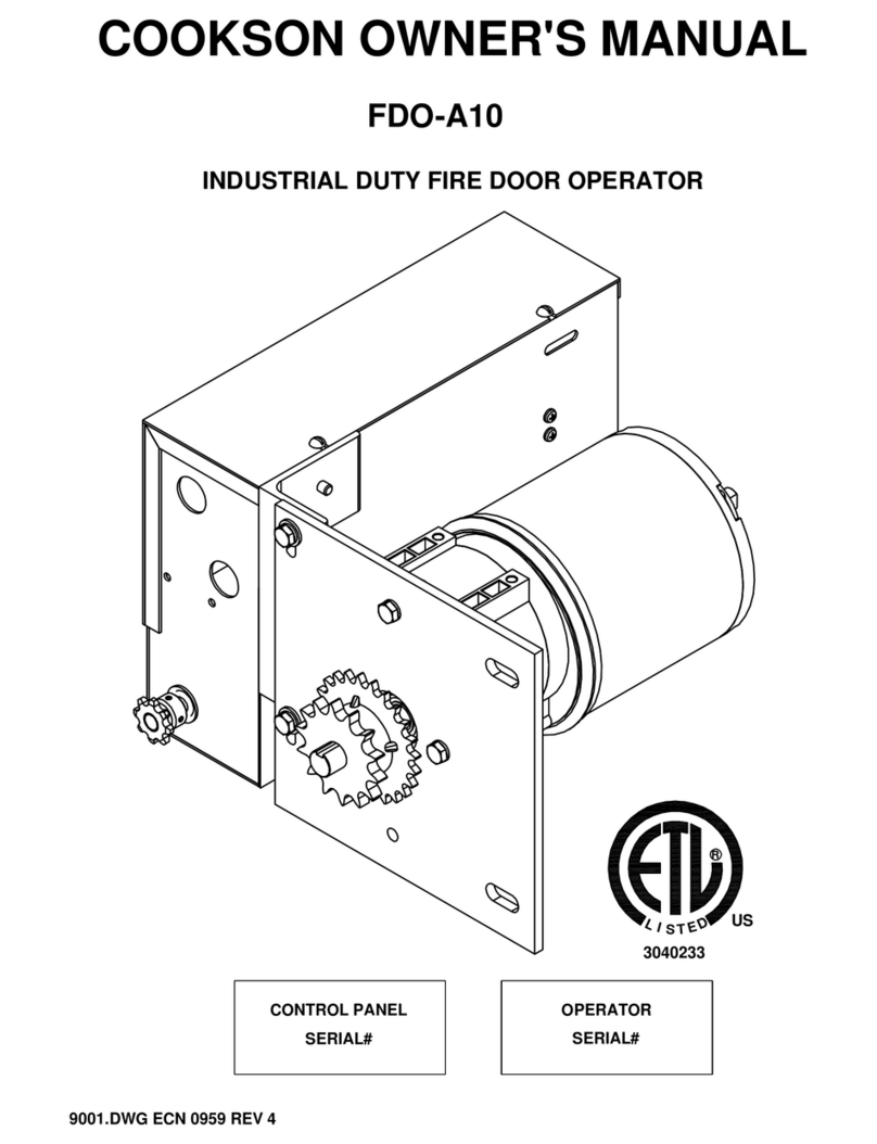
Cookson FDO-A10E User manual

COOKSON OWNER'S MANUAL
INDUSTRIAL DUTY FIRE DOOR OPERATOR
FDO-A10E
9001(7) ECN 1057 4/10/010
XXXXXXX
R
US
SERIAL#
OPERATOR
IMPORTANT SAFETY INSTRUCTIONS
SAVE THESE INSTRUCTIONS
WARNING
NOT FOR RESIDENTIAL USE

SPECIFICATIONS
MOTOR ELECTRICAL
TYPE:.......................................INTERMITTENT
HORSEPOWER:......................1/8 H.P.
VOLTAGE:...............................115 SINGLE PHASE
CURRENT:...............................2.5 AMP
DC POWER SUPPLY:.............24VDC, 15W
CONTROL STATION:..............NEMA 1 3 BUTTON STATION
OPEN/CLOSE/STOP
WIRING TYPE:.........................C2/B2 (STANDARD)
LIMIT ADJUST:........................LINEAR DRIVEN, FULLY
ADJUSTABLE SCREW TYPE CAMS
MECHANICAL
DRIVE REDUCTION:..............43:1 REDUCTION IN LINE
GEAR REDUCED MOTOR
OUTPUT SHAFT SPEED:......29 R.P.M.
DOOR SPEED:........................12" PER SECOND
BRAKE:...................................SOLENOID ACTUATED
DISC BRAKE
MOUNTING DIMENSIONS
2
9001(7) ECN 1057 4/10/010
4.938
14.125
8.06
12.42
5.92
6.00
MAX LOAD:...............................250 IN-LBS

THEORY OF OPERATION
GENERAL DESCRIPTION:
The UL-325 compliant Fire Door Operator, FDO-A10, is an integrated fire door control system. It is
designed to interface with Normally Closed (NC) or Normally Open (NO) dry contacts from the alarm
1. FDO-A10 MODEL: (With entrapment detection devices installed and working properly.
1.1 UNIT HAS AC POWER & NO ALARM CONDITION:
NOTICE
THIS OPERATOR IS NOT A FIRE ALARM SYSTEM.
IT CAN NOT DETECT A FIRE CONDITION
The B2 control station is used to operate the door
electrically.
Activation of the sensing edge or Photo eyes while door is closing
will cause it to reverse to full open limit.
1.2 ALARM CONDITION W/ AC POWER:
Door begins closure after a preset time delay of 0 or 10 seconds (Set at 10 seconds
If obstruction is encountered by entrapement protection device(s), door will reverse to
OPEN position and attempt closure again. The door will cycle up to 3 times before
resting on the obstruction. If the obstruction is removed, the door will continue to the
fully CLOSED position.
The OPEN button will raise the door to the fully open position, and after a 10 second
delay will begin closing again. This will work until the third attempt to close has been
used, and then all OPEN functions will be disabled until the alarm has been reset.
system or initiating device to control the operation of a fire door. The control station will operate
TO REDUCE THE RISK OF INJURY TO PERSONS,
USE THIS OPERATOR ONLY WITH ROLLING DOORS.
WARNING
3
with either standard B2 or C2 wiring. This operator will require the proper self diagnostic entrapment
protection device(s) to be connected and working properly to allow B2 (Momentary Pressure on the
Close button) to close the door.
on basic unit, 0 second selectable if unit is equipped with expansion module).
Note: All OPEN functions initiated by the photo eyes or sensing edge can be disabled
in the event of an active alarm condition, if the unit is equipped with the expansion module.
When this feature is selected, and an obstruction is detected by the entrapement
protection device(s), the door will rest on the obstruction. If the obstruction is later
9001(7) ECN 1057 4/10/010
removed, the door will travel to the fully CLOSED position.
The FDO-A10E medium duty motor operator is designed for use only with Service Counter Fire
Door models FD1O-1M and FD10-2M as manufactured by the Cookson Company Inc.
Door sizes range from 4'-0" x 4'-0" to 14' max opening width to 9'-0" max clear opening height.
(Smaller doors may be available with Engineering approval on a case-by-case basis.

4
9001(7) ECN 1057 4/10/010
WARNING - TO REDUCE THE RISK OF SEVERE INJURY OR DEATH:
The unit is not functional and the brake is released.
(This unit when equipped with the Expansion Module is available with an optional Battery
Back-Up power unit)
the alarm contacts for a change of status for up to 12 hours. With the battery back-up
power unit the door will stay in the open position until the batteries have become depleted,
12 hours have elapsed with no power, or a change of status in the alarm contact has
occured. If one of these events occur, the unit is not functional and the brake will be
released. The door will close without delay. 5 minutes prior to this closure the unit will
This power unit will keep the processor in the controller energized and continue to monitor
activate the output for the sounder strobes to give a pre-closure warning.
IMPORTANT INSTALLATION INSTRUCTIONS
1) READ AND FOLLOW ALL INSTALLATION INSTRUCTIONS.
2) Install only on a properly operating door. A door that is operating improperly could cause
severe injury. Have qualified service personnel make repairs to cables, spring assemblies,
and other hardware before installing this operator.
3) The Firedoor Controller will not close a balance door in the absence of AC power. The door
system must be able to generate a minimum backdriving torqueof 50 in-lbs. at the operator
output shaft. Sticking or binding doors must be repaired. Doors, door springs, brackets and
their hardware may be under extreme tension and cause serious personal injury. Call a
professional door serviceman to move or adjust door springs or hardware.
4) Remove all pull ropes and remove, or make inoperative, all locks (Unless mechanically
and/or electrically interlocked to the power unit) that are connected to the door before
installing the operator.
5) Install the door operator at least 8 feet or more above the floor if the operator has exposed
moving parts.
6) Do not connect the door operator to the source of power until instructed to do so.
7) Locate the control station: (a) within sight of the door, (b) at a minimum height of 5 feet
so small children cannot reach it, and (c) away from all moving parts of the door.
8) Install the Entrapement Warning Placard next to the control station in a prominent
location.
IMPORTANT SAFETY INSTRUCTIONS
WARNING - TO REDUCE THE RISK OF SEVERE INJURY OR DEATH:
1) READ AND FOLLOW ALL INSTRUCTIONS.
2) Never let children operate or play with door controls. Keep the remote control (where
provided) away from children.
3) Personnel should keep away from a door in motion and keep the moving door in sight
until it is completely closed or opened. NO ONE SHOULD CROSS THE PATH OF A MOVING
DOOR.
THEORY OF OPERATION (CONT.)

OPERATOR MOUNTING
Before your operator is installed, be sure the door has been properly aligned and is working
smoothly. Refer to the Door Installation Instructions for proper operator installation. This
motor operator is an integral part of the door system. The motor operator and governor (if
provided) controls door descent speed under power outage conditions.
5
9001(7) ECN 1057 4/10/010
IMPORTANT SAFETY INSTRUCTIONS (CONT.)
4) Test the door's safety features at least once a month. After adjusting either the force or the
limit of travel, retest the door operator's safety features. Failure to adjust the operator
properly may cause severe injury or death.
5) KEEP DOORS PROPERLY OPERATING AND BALANCED. See Door Manufacturer's Owner's
Manual. An improperly operating or balanced door could cause severe injury or death. Have
trained door systems technician make repairs to cables, spring assemblies and other hardware.
6) SAVE THESE INSTRUCTIONS.
ELECTRICAL
1) DISCONNECT POWER AT THE FUSE/BREAKER BOX/DISCONNECT BEFORE PROCEEDING
WITH ANY WIRING OF THIS UNIT.
2) THE UNIT MUST BE PROPERLY GROUNDED. A GROUND SCREW IS SUPPLIED IN THE
ELECTRICAL BOX FOR CONNECTION OF THE POWER SUPPLY GROUND WIRE. FAILURE
TO PROPERLY GROUND THIS UNIT COULD RESULT IN ELECTRICAL SHOCK AND
SERIOUS INJURY.
3) FIELD WIRING OF OPERATOR MUST BE PERFORMED BY QUALIFIED PERSONNEL.
4) OPERATOR MUST BE WIRED PER WIRING DIAGRAMS PROVIDED IN THIS OWNERS
MANUAL ONLY.
5) OPERATOR MUST BE WIRED IN ACCORDANCE WITH LOCAL ELECTRICAL CODES.
NOTE: THE OPERATOR SHOULD BE ON A SEPARATE FUSED LINE OF ADEQUATE
CAPACITY.
6) USE 18 GA STRANDED COPPER WIRE MINIMUM FOR ALL CONTROL CIRCUIT
CONNECTIONS.
7) DO NOT INSTALL ANY WIRING OR ATTEMPT TO RUN THE OPERATOR WITHOUT
CONSULTING THE WIRING DIAGRAM.
8) SET OPERATOR LIMIT SWITCHES BEFORE CONNECTING ANY ENTRAPEMENT
PROTECTION DEVICES TO THE OPERATOR.

ENTRAPMENT PROTECTION ACCESSORIES
In accordance with UL-325 requirements, this operator requires specific primary entrapment
detection devices connected and working properly before B2 (momentary contact) on the CLOSE
control station is enabled. Without the proper primary entrapment detection accessories connected
and working properly, the unit will require constant pressure on the CLOSE control station to close,
during normal operation. DO NOT ATTEMPT TO BYPASS OR DEFEAT THIS FEATURE. Damage to
the unit is possible. This damage is not covered under the manufacturer's warranty.
IMPORTANT NOTES:
1) Proceed with Limit Switch Adjustments before making any connections from the entrapment
protection devices (If equipped) to the operator as described below.
2) Verify that the alarm terminals (3 and 11) are connected to a normally closed (NC) circuit
before applying power to the operator controller.
6
When a second entrapment protection device is desired, any device with a normally OPEN (N/O)
dry contact type output is compatible with this door. (See control connection diagram for
connections). Entrapement protection will not function when the CLOSE limit switch is activated.
9001(7) ECN 1057 4/10/010
AN ALARM DEVICE MUST BE CONNECTED TO THE ALARM INPUT BEFORE
INSTALLATION IS COMPLETE.
DURING INITIAL SETUP MAKE SURE A CLOSED CIRCUIT IS CONNECTED TO ALARM
INPUT. FAILURE TO DO SO MAY CAUSE THE OPERATOR TO ACTIVATE SUDDENLY
WITHOUT WARNING.
ALARM INPUTS
1) Alarm inputs (Terminals 5 & (-) minus) may be used to supply 24VDC for electronic alarm devices
such as smoke detectors or similar systems. The alarm activation must be normally closed and must
open in an alarm condition. If a normally closed contact is not available, a normally open (NO)
contact may be used between terminals 12 & 13 with a jumper wire installed between terminals
3 & 11. If this option is used, the (NO) contact must close in an alarm condition. See sheet 12 for
an example of wiring a typical 4-wire smoke detector.

LIMIT SWITCH ADJUSTMENT
MAKE SURE THE LIMIT NUTS ARE POSITIONED BETWEEN THE LIMIT SWITCH ACTUATORS
BEFORE PROCEEDING WITH ADJUSTMENTS. MAKE SURE OPENING AND THE AREA NEAR
DOOR/OPERATOR AND MECHANISMS ARE CLEAR OF OBSTRUCTIONS AND PERSONNEL.
1) To adjust limit nuts depress retaining plate to allow nut to spin freely. After adjustment,
ELECTRIC POWER BEFORE MANUALLY MOVING LIMIT NUTS.
TO AVOID SERIOUS PERSONAL INJURY OR DEATH FROM ELECTROCUTION, DISCONNECT
WARNING
release plate and ensure it seats fully in slots of both nuts.
2) To increase door travel, spin nut away from actuator. To decrease door travel, spin limit
nut toward actuator.
3) Adjust open limit nut so that door will stop in open position with the bottom of the door
even with top of door opening.
4) Repeat Steps 1 and 2 for close cycle. Adjust close limit nut so that actuator is engaged
as door fully seats at the floor.
6) Connect sensing edge to controller terminals 3 & 10 and test operation - if equipped.
CLOSE LIMIT SWITCH
OPEN LIMIT SWITCH
LIMIT NUTS
RETAINING
PLATE
7
5) Connect Photo Electric Sensors per the wiring diagram on page 10 and test operation.
9001(7) ECN 1057 4/10/010


COVER
WARNING
A COVER MUST BE INSTALLED OVER DOOR BRACKET & MOTOR SPROCKETS
WHEN MOVING PARTS ARE EXPOSED LESS THAN 8 FT FROM THE FLOOR
9
9001(7) ECN 1057 4/10/010
FDO-A10 COVER
PLEASE REFER TO DOOR
INSTALLATION MANUAL
FOR PROPER MOTOR
CONNECTION AND
ORIENTATION ON DOOR

FDO-A10 WIRING DIAGRAM
CAUTION: DISCONNECT POWER BEFORE
1) IF UNIT IS EQUIPPED WITH EXPANSION MODULE SEE PAGE
OPENING COVER AND INSTALLATION.
NOTES:
WIRE SCHEDULE
VOLTAGE
120VAC
24VDC
18GA
18GA
WIRE GAGE
10
9001(7) ECN 1057 4/10/010
10 FOR ADDITIONAL WIRING CONNECTIONS.
2) RIGHT HAND DOORS SHOWN. FOR LH DOORS: SWITCH
ORANGE AND PURPLE WIRES ON SMART RELAY
Q1-2 AND Q2-2 FOR DIRECTION CHANGE.
3) SEE CONTROL CONNECTION DIAGRAM FOR FIELD
WIRING CONNECTIONS.
BASE UNIT
123
4510-
111213 M
L1L2
+

FDO-A10 WIRING DIAGRAM
(PG9) FOR ADDITIONAL INFORMATION.
1. REFER TO BASIC WIRING DIAGRAM
NOTES:
11
9001(7) ECN 1057 4/10/010
CAUTION: DISCONNECT POWER BEFORE
OPENING COVER AND INSTALLATION.
UPGRADED UNIT W/ADDENDUM
JUMPER CONFIGURATIONS
TERMINALS
+ TO 20 = CHANGES SOUNDER STROBE
FROM ACTIVATION ON ALARM ONLY TO
ANY TIME THE MOTOR IS MOVING THE
DOOR.
+ TO 19 = CHANGES ALARM CLOSURE
DELAY FROM 10 SECONDS TO
IMMEDIATE.
+ TO 21 = WILL CAUSE DOOR TO RETURN
TO THE FULLY OPEN POSITION ON ALARM
RESET.
+ TO 22 = WILL DISABLE ANY OPEN FUNCTION
DURING AN ACTIVE ALARM CONDITION. DOOR
WILL STOP AND NOT RELEASE UPON CONTACT
WITH AN OBSTRUCTION, AND OPEN BUTTON
WILL NOT OPERATE. THIS SETTING ONLY
AFFECTS OPERATION DURING AN ACTIVE
ALARM CONDITION.
DO NOT SELECT THIS OPTION UNTIL ALL OTHER
FUNCTIONS OF DOOR HAVE BEEN VERIFIED AND
WARNING
LIMITS HAVE BEEN SET. PERSONAL INJURY OR
EQUIPMENT DAMAGE COULD RESULT.
L1L2
S-S++ 212019 22
123
4510-
111213 M

CONTROL CONNECTION DIAGRAM
IMPORTANT NOTES:
1) The 3-Button Control Station provided must be connected for operation.
ATTENTION ELECTRICIAN : USE 18 GAUGE STRANDED COPPER OR HEAVIER WIRE
FOR ALL CONTROL CIRCUIT WIRING
3 BUTTON STATION OR 3 POSITION KEYSWITCH W/SPRING RETURN
STANDARD
TO CENTER AND STOP BUTTON
2 OR MORE
1 2 3 4
OPEN
CLOSE
STOP STOP
CLOSE
OPEN
21 3 4
STOP
CLOSE
OPEN
EXTERNAL INTERLOCK
(FOR DOOR LOCKS ONLY)
3 5 53
ONE 2 OR MORE
REMOVE JUMPER
WHEN INTERLOCK IS USED
ALL CONTROL WIRING TYPES ALL CONTROL WIRING TYPES
ALL CONTROL WIRING TYPES
NORMALLY CLOSED ALARM
311 12 13
CLOSED
CIRCUIT
N/C ALARM
12
STOP
CLOSE
OPEN
4321
WITH KEY LOCKOUT
3 BUTTON PUSH BUTTON STATION
KEY
LOCKOUT
NORMALLY
9001(7) ECN 1057 4/10/010
PHOTO EYE
CONNECTIONS
311 3 11
JUMPER
OR
AND
FUSE LINK
SWITCH
OPTIONAL FUSE LINK SWITCH
12 13
NORMALLY OPEN ALARM
OPTIONAL FUSE LINK SWITCH
1
2
3
4
5
DIP SWITCHES #1 AND #2 ARE
TO BE SET IN THE OFF POSTITION
ONLY (TOWARDS THE NUMBERS)
1
2
3
4
5
Photo Eye
Terminals
Operator
Terminals
24 VDC
Contacts
5
-
M
10
3
Sensing Edge or Other Secondary
Entrapment Protection Device (optional)
PHOTE EYES (WHEN EQUIPPED) ARE TO BE INSTALLED 6" ABOVE FINISHED FLOOR

CONTROL CONNECTION DIAGRAM
13
9001(7) ECN 1057 4/10/010
EXPANSION MODULE TERMINAL STRIP WITH OUTPUT TO SOUNDER STROBES
SMOKE DETECTOR WIRING
SINGLE DOUBLE
SOUNDER STROBE SOUNDER STROBE

BATTERY BOX OPTION WIRING INSTRUCTIONS (OPTIONAL)
14
9001(7) ECN 1057 4/10/010
CONNECTOR
PLUG
FROM
BATTERY BOX
CONTROL
PANEL
BATTERY
BOX
FOLLOW DIRECTIONS
PROVIDED ON BATTERY
BOX INSERT FOR BATTERY
CHARGER CONNECTIONS
NOTE: BATTERY BOX WILL NOT OPERATE
MOTOR. IT WILL KEEP CIRCUITS AND
BRAKE ENERGIZED IN THE EVENT OF
POWER LOSS. IT WILL MONITOR ALARM
SYSTEM AND CLOSE DOOR IF ACTIVE
ALARM CONDITION IS DETECTED, THE
CLOSE BUTTON IS DEPRESSED, OR THE
BATTERIES HAVE BECOME DEPLETED
OR UNIT HAS BEEN WITHOUT POWER
FOR 12 HOURS OR MORE.
+
_
LOW VOLTAGE ONLY
24VDC 0.6 A

BATTERY BOX WIRING DIAGRAM
15
9001(7) ECN 1057 4/10/010

MOVING DOOR WARNING PLACARD
16
9001(7) ECN 1057 4/10/010
INSTALL MOVING DOOR WARNING PLACARD IN A CONSPICUOUS PLACE NEAR OPEN/CLOSE/STOP
STATION AS INDICATED
WARNING
PLACARD
OPEN/CLOSE/STOP
STATION
PLEASE REFER TO DOOR
INSTALLATION MANUAL
FOR PROPER MOTOR
CONNECTION AND
ORIENTATION ON DOOR

MAINTENANCE SCHEDULE
CHECK AT THE INTERVALS LISTED IN THE FOLLOWING CHART.
ITEM PROCEDURE EVERY EVERY EVERY
3 MONTHS 6 MONTHS 12 MONTHS
Drive Chain Check for excessive slack.
Check & adjust as required.
Lubricate.* X X
Sprockets Check set screw tightness X X
Fasteners Check & tighten as required X
Bearings/Shafts Check for wear & lubricate X X
Gearbox - The gearbox on the motor operator is factory sealed, and non vented, and should not
require service for the life of the operator.
Brake Friction Material - The electromagnetic brake on the motor operator is factory adjusted,
and should not require service for the life of the operator. Should service be
required, the entire unit should be replaced.
* - Use SAE 30 Oil (Never use grease or silicone spray)
Do not lubricate motor. Motor bearings are lubricated and sealed at the factory.
Inspect and service whenever a malfunction is observed or suspected.
CAUTION: BEFORE SERVICING, ALWAYS DISCONNECT OPERATOR FROM POWER SUPPLY.
WHEN ORDERING REPAIR PARTS PLEASE SUPPLY THE FOLLOWING INFORMATION:
PART NUMBER - DESCRIPTION - MODEL NUMBER - JOB NUMBER
ADDRESS ORDER TO:
COOKSON ROLLING DOORS
2417 S. 50TH AVE
PHOENIX, AZ. 85043
(602) 272-4244
ATTN: CUSTOMER SERVICE
MOTOR OPERATOR MAINTENANCE
Operators require practically no special maintenance other than periodic checking to see that
mechanical parts where necessary are lubricated and the electrical components are free of dirt.
The Service Technician should familiarize himself/herself with the proper sequence of operation
and all related controls. Power to operator must be disconnected when removing or replacing
covers on electrical components, making adjustments, or performing maintenance.
17
9001(7) ECN 1057 4/10/010

MOTOR OPERATOR MAINTENANCE
MOTOR OPERATOR TROUBLE SHOOTING GUIDE
14. Check motor amperage draw for a full open and close cycle. Compare readings to those
9. Inspect the electrical enclosure for debris, arcing and moisture. Check for and tighten
8. Verify that all conduit connections are tight and have no exposed wires.
7. Generally inspect the motor mounting, and tighten the fasteners and bracing.
6. Inspect roller chain and drive sprockets. Align, lubricate the sprockets, and tighten the set screws.
1. Check wire connections for tightness and wire insulation for defects or abrasions.
listed on the motor nameplate.
13. Test the operation of the safety edge.
12. Examine safety edge, coil cord and take up reel for damage.
11. Check limit switch settings.
10. Test motor operation through all control stations.
loose wiring connections.
5. Inspect gearbox for leaks.
4. Inspect operation of brake.
3. Check wires to safety edge or photo-eyes.
2. Check to see that all conduit connections are secure.
SYMPTOM POSSIBLE CAUSE REPAIR
Motor does not run when
OPEN or CLOSE button is Circuit breaker tripped or power
fuse blown Check circuit breaker, power
fuses, safety switch, check cause
Thermal overload tripped Reset; check cause
DC Power Supply damaged Replace
pushed
External interlock open. (if supplied) Close interlocks
Motor runs but door
does not move Sprocket key missing or drive chain
broken. Check drive train for operation
Intermediate shaft or key damaged. Close & lock off door, remove
motor and inspect; check cause
Motor hums but does
not run Door jammed. Drive train jammed. Check door. Try to operate
manually
Brake does not release. Check power to brake coil.
Open motor winding Check all motor connections.
Operator runs in wrong
direction and limits do
not function
Motor leads are reversed Interchange Purple and Orange
wires (Q1 & Q2) Smart Relay
Note: All units are checked for proper rotation at factory. Limit switch
adjustment instructions in electrical enclosure indicates proper
direction of travel for OPEN and CLOSE limit nuts.
Limit switches do not
hold their settings. Drive chain loose, allows chain to
jump sprocket teeth. Adjust chain to proper tension.
Limit nut retainer not engaging
slots in limit nuts. Be sure retainer is in slots of
BOTH units
Limit nuts binding on screw threads
which allows them to jump
position on retainer.
Lubricate screw thread. Limit nuts
should turn freely.
Door "drifts" when motor
shuts off. Brake inoperative or worn Check brake operation.
Operator does not shut
off at full OPEN or at full
CLOSE position
Limit nuts not adjusted properly. Adjust (See above)
Sprocket on limit shaft loose
or limit drive chain broken Inspect limit chain & sprocket.
Adjust chain tension, replace
sprocket & chain if required.
Defective limit switch Operate limit switch manually
to determine.
18
9001(7) ECN 1057 4/10/010
Table of contents
Other Cookson Door Opening System manuals
Popular Door Opening System manuals by other brands

LCN
LCN 4050 Track Series installation instructions

Resolution Products
Resolution Products RE102 quick guide

Carlisle Brass
Carlisle Brass CDG003 installation instructions

B&D
B&D Smart Pro Quick operation guide

Next Systems
Next Systems 900 INSTRUCTIONS MANUAL FOR THE USE & MAINTENANCE

cinetto
cinetto PS23 Assembly instructions